17.1 - 2300 E 2nd-2341 Corta St - elevations — original pdf
Backup
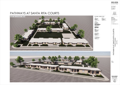
PATHWAYS AT SANTA RITA COURTS ISSUED FOR: SCHEMATIC DESIGN PROJECT DIRECTORY LANDSCAPE: DWG 912B Congress Avenue Austin, Texas 78701 512.320.0668 CONTACT: Ethan Primm OWNER: Carleton Company 1700 E 3rd Street Austin, Texas 78702 972.980.9810 CONTACT: Will Henderson ARCHITECT: Nelsen Partners, Inc. 905 Congress Ave. Austin, Texas 78701 512.531.7350 CONTACT: Matt Beaton @ . Urban Foundry Architecture 1306 Rio Grande Street Austin, Texas 78701 512.294.2555 CONTACT: Jeff Needles @ . CIVIL: Dunaway 5707 Southwest Parkway Building 2, Suite 250 Austin, Texas 78735 512.306.8252 CONTACT: J Segura STRUCTURAL ENGINEER: Connect Structural 9330 LBJ Freeway #1000 Dallas, Texas 75234 214.221.2220 CONTACT: Nathan Cole MEP ENGINEER: PHA Consulting Engineers 1130 E. Arapaho Rd. Suite 300 Richardson, Texas 75081 972.235.2192 CONTACT: Randy Visser PRELIMINARY: NOT FOR REGULATORY APPROVAL, PERMITTING, OR CONSTRUCTION Urban Foundry Architecture 1306 Rio Grande Street Austin, Texas 78701 p: 512 . 294 . 2555 www.urbanfoundryarchitecture.com 2 0 7 8 7 X T , I N T S U A i s e n a p m o C n o e l r a C t . T S D N 2 E 0 0 3 2 I S T R U O C A T R A T N A S T A S Y A W H T A P Date 8/1/2025 Revisions Drawings and written material appearing herein constitute original and unpublished work of the architect and may not be duplicated, used, or disclosed without written consent of the architect. © 2023 NELSEN PARTNERS, INC. UFA Commission No.: 100995 G001 COVER SANTA RITA ST UNIT 1A UNIT 1A UNIT 1A UNIT 2B UNIT 2A-A UNIT 2B DN 2 T T 1 T S D S D T 4 5 UNIT 2D UNIT 2D UNIT 1B UNIT 1B UNIT 1C-A 6 UNIT 1D-A UNIT 1E UNIT 2D UNIT 2D UNIT 1B UNIT 1B 7 T 8 T T 11 UNIT 1A UNIT 1A UNIT 1A UNIT 1E T 10 UNIT 1D UNIT 1C S D T E T E E R E T R S T S S S E E L L A A N N R R E D E E D P E P UNIT 2C 3 UNIT 2C UNIT 2A T 9 UNIT 2A CONCRETE CURB & 1 SITE PLAN OVERALL E 2ND STREET S D SITE BUILDING PLAN LEGEND 1 BEDROOM UNIT 2 BEDROOM UNIT 16 ONE-BEDROOM UNITS 11 TWO-BEDROOM UNITS. 11 EXISTING HISTORIC BUILDINGS - 1 STORY 27 UNITS PRELIMINARY: NOT FOR REGULATORY APPROVAL, PERMITTING, OR CONSTRUCTION Urban Foundry Architecture 1306 Rio Grande Street Austin, Texas 78701 p: 512 . 294 . 2555 www.urbanfoundryarchitecture.com 2 0 7 8 7 X T , I N T S U A i s e n a p m o C n o e l r a C t . T S D N 2 E 0 0 3 2 I S T R U O C A T R A T N A S T A S Y A W H T A P Date 8/1/2025 Revisions UNIT MIX Drawings and written material appearing herein constitute original and unpublished work of the architect and may not be duplicated, used, or disclosed without written consent of the architect. © 2023 NELSEN PARTNERS, INC. UFA Commission No.: 100995 G004 SITE BUILDING PLAN & UNIT MIX 2 02.01 02.01 6 SANTA RITA ST 5/8" / 1'-0" DN 02.14 02.11 1 02.01 DN 3 02.01 DN 02.11 1.7 02.11 02.01 4 7 02.01 5 8 T E T E E R E T R S T S S S E E L L A A N N R R E D E E D P E P 02.01 02.01 02.11 9 02.01 02.01 11 02.11 02.11 10 02.14 02.11 E 2ND STREET KEYED NOTES Key Value 1.7 Keynote Text 02.01 Carefully deconstruct and remove all existing flooring, walls, doors, frames, hardware, ceiling, roof, and equipment of the water heater closet. 02.11 Carefully deconstruct and remove existing railings. 02.14 Carefully deconstruct and remove existing ramp. PRELIMINARY: NOT FOR REGULATORY APPROVAL, PERMITTING, OR CONSTRUCTION Urban Foundry Architecture 1306 Rio Grande Street Austin, Texas 78701 p: 512 . 294 . 2555 www.urbanfoundryarchitecture.com 2 0 7 8 7 X T , I N T S U A i s e n a p m o C n o e l r a C t . T S D N 2 E 0 0 3 2 I S T R U O C A T R A T N A S T A S Y A W H T A P Date 8/1/2025 Revisions 01 EXISTING SITE PLAN SCALE : 1/16" = 1'-0" Drawings and written material appearing herein constitute original and unpublished work of the architect and may not be duplicated, used, or disclosed without written consent of the architect. © 2023 NELSEN PARTNERS, INC. UFA Commission No.: 100995 HA000 EXISTING SITE PLAN 02.15 SD SD SD 02.10 SD SD SD SD SD SD SD SD SD SD 02.15 03 BUILDING 1 - DECONSTRUCTION ROOF PLAN SCALE : 1/8" = 1'-0" PLAN TAKEN ON BUILDING 1 02.15 02.06 02.07 02.15 02.07 SD 02.13 02.13 SD 02.07 02.15 SD SD SD SD SD 02.13 SD 02.13 SD SD SD SD SD 02.13 02.13 02.13 02.13 02.01 02.01 02.06 02.06 02.01 02.15 02 BUILDING 1 - DECONSTRUCTION RCP SCALE : 1/8" = 1'-0" PLAN TAKEN ON BUILDING 1 02.11 02.06 02.02 02.05 2 0 2 A H / 5 0 1 0 2 A H / 7 0 02.16 01.01 01/HA201 02.05 02.16 02.08 02.12 02.04 02.03 01.01 02.05 02.06 02.04 02.08 02.04 02.03 02.14 02.11 01.01 02.02 02.08 02.02 02.02 02.04 02.02 02.06 02.04 02.03 02.08 02.01 02.06 02.01 02.06 02.01 02.01 02.05 02.01 02.16 02.06 02.01 01.02 01.02 03/HA201 01 BUILDING 1 - DECONSTRUCTION PLAN SCALE : 1/8" = 1'-0" PLAN TAKEN ON BUILDING 1 02.06 02.07 02.15 02.16 02.06 1 0 2 A H / 5 0 02.11 PLAN NOTES: 01. Refer to Index Sheet for typical graphical symbols and abbreviation index. 02. Refer to Code Analysis Sheet for Accessibility Guidelines. 03. 04. 05. In general, all horizontal dimensions are provided on plans, and all vertical dimensions are provided on elevations and/or sections unless otherwise noted. In general, the Overall Plan indicates exterior building dimensions, room numbers and names, door designations, exterior window designations, exterior elevations designations, building section and details designations. All other plan information is indicated on referenced area or enlarged plans. In general, Area and/or Enlarged Plans indicate interior building dimensions to face of partition material, room numbers and names, door designations, interior window designations, interior detail designations, interior elevations, partition type designations, finish designations, and general building material. 06. When columns and column lines are present, all dimensions are to be tied to a column line. Contractor shall immediately report any omission of dimensions not tied to a column line to the architect prior to start of construction. 07. Coordinate all MEP access panels not shown on architectural construction documents with Architect prior to installation. 08. 09. 10. 11. 12. Provide adequate blocking as required at every location where millwork, wall light fixtures, railings, TV brackets, plumbing fixtures, etc. are to be mounted. Items are required to resist 250 pound point load. There are items shown, i.e. outlets, switches, thermostats, panels, etc. on MEP contract documents that may not be shown on architectural contract documents. Contractor to coordinate all items with current TAS requirements and mounting height sheet unless noted otherwise. Storage type water heaters that exceed 17 gallons shall not be installed 8ft or more above the finish floor. Ref. Interior Elevation for water heater platform height. Fire sprinkler shop drawings, designed in accordance with NFPA 13 by a Texas licensed sprinkler contractor or engineer, will be submitted for review and approval by the GC, and inspected by AFD. Fire alarm shop drawings, designed in accordance with NFPA 72 by a Texas licensed fire alarm contractor or engineer, will be submitted for review and approval by the GC, and inspected by AFD. 13. Upon deconstructing and removing the roof, carefully remove all existing MEP elements and patch all existing openings to the roof. PLAN LEGEND: SYMBOL DESCRIPTION AREA NOT IN CONTRACT. NO WORK TO BE DONE IN THIS AREA. PROTECT. EXISTING PARTITION REMAINS. PROTECT. NEW PARTITION. REFER TO PARTITION SCHEDULE. ONE (1) HOUR FIRE RATED PARTITION. SELECTIVE DECONSTRUCTION OF PARTITION. NEW DOOR. REFER TO NOTES AND/OR SCHEDULE. REMOVE DOOR AND FRAME. LEGEND GENERAL NOTES: 1. NOT ALL SYMBOLS MAY BE USED ON THIS PROJECT. REFER TO PLANS. KEYED NOTES KEYED NOTES Key Key Value Value Keynote Text Keynote Text 01.01 Existing pipe columns to remain. Refinish to "As New" 01.01 Existing pipe columns to remain. Refinish to "As New" appearance. appearance. 01.02 Existing pipe rail to remain at all back patios. Refinish to "As 01.02 Existing pipe rail to remain at all back patios. Refinish to "As New" appearance. New" appearance. 02.01 Carefully deconstruct and remove all existing flooring, walls, 02.01 Carefully deconstruct and remove all existing flooring, walls, doors, frames, hardware, ceiling, roof, and equipment of the doors, frames, hardware, ceiling, roof, and equipment of the water heater closet. water heater closet. 02.02 Carefully deconstruct and remove existing millwork along with 02.02 Carefully deconstruct and remove existing millwork along with the associated plumbing fixtures throughout. the associated plumbing fixtures throughout. 02.03 Carefully deconstruct and remove all existing interior doors, 02.03 Carefully deconstruct and remove all existing interior doors, frames, and hardware. frames, and hardware. 02.04 Carefully deconstruct and remove all existing interior partitions. 02.04 Carefully deconstruct and remove all existing interior partitions. 02.05 Carefully deconstruct and remove all existing exterior doors 02.05 Carefully deconstruct and remove all existing exterior doors and hardware. Door frames to be restored and reused. and hardware. Door frames to be restored and reused. 02.06 Carefully deconstruct and remove all existing windows, blinds 02.06 Carefully deconstruct and remove all existing windows, blinds and any associated trim. and any associated trim. 02.07 Carefully deconstruct and remove all existing wall mounted 02.07 Carefully deconstruct and remove all existing wall mounted light fixtures and associated exposed conduit. light fixtures and associated exposed conduit. 02.08 Carefully deconstruct and remove all existing flooring 02.08 Carefully deconstruct and remove all existing flooring throughout. throughout. 02.10 Carefully deconstruct and remove existing shingle roof, 02.10 Carefully deconstruct and remove existing shingle roof, substrate, loose fill insulation, gabled roof framing, and all roof substrate, loose fill insulation, gabled roof framing, and all roof elements. Existing concrete roof slab to remain & protect. elements. Existing concrete roof slab to remain & protect. 02.11 Carefully deconstruct and remove existing railings. 02.11 Carefully deconstruct and remove existing railings. 02.12 Carefully deconstruct and remove existing load bearing 02.12 Carefully deconstruct and remove existing load bearing masonry wall, provide temporary shoring per struct. masonry wall, provide temporary shoring per struct. 02.13 Carefully deconstruct and remove all existing ceilings along 02.13 Carefully deconstruct and remove all existing ceilings along with all associated light fixtures and sensors. with all associated light fixtures and sensors. 02.14 Carefully deconstruct and remove existing ramp. 02.14 Carefully deconstruct and remove existing ramp. 02.15 Carefully deconstruct and remove all existing fascia. Protect 02.15 Carefully deconstruct and remove all existing fascia. Protect and prep for scupper attachment. and prep for scupper attachment. 02.16 Carefully remove all existing paint on the exterior wall. 02.16 Carefully remove all existing paint on the exterior wall. PRELIMINARY: NOT FOR REGULATORY APPROVAL, PERMITTING, OR CONSTRUCTION Urban Foundry Architecture 1306 Rio Grande Street Austin, Texas 78701 p: 512 . 294 . 2555 www.urbanfoundryarchitecture.com 2 0 7 8 7 X T , I N T S U A i s e n a p m o C n o e l r a C t . T S D N 2 E 0 0 3 2 I S T R U O C A T R A T N A S T A S Y A W H T A P Date 8/1/2025 Revisions KEY PLAN LEGEND: 2 1 6 4 5 7 8 11 10 3 9 Project North True North Drawings and written material appearing herein constitute original and unpublished work of the architect and may not be duplicated, used, or disclosed without written consent of the architect. © 2023 NELSEN PARTNERS, INC. UFA Commission No.: 100995 HA001 BUILDING 1 DECONSTRUCTION PLAN, RCP & ROOF SD SD SD SD 02.15 02.10 SD 02.15 SD SD SD SD 03 BUILDING 2 & 11 - DECONSTRUCTION ROOF PLAN SCALE : 1/8" = 1'-0" PLAN TAKEN ON BUILDING 2 02.15 02.06 02.07 02.13 SD 02.13 SD 02.13 02.13 02.06 02.07 02.15 SD SD SD SD SD SD SD 02.13 02.13 02.13 02.13 02.13 02.01 02.15 02.07 02.01 02.06 02.15 02.06 02.07 02 BUILDING 2 & 11 - DECONSTRUCTION RCP SCALE : 1/8" = 1'-0" PLAN TAKEN ON BUILDING 2 02.05 02.06 01.01 2 0 2 A H / 7 0 02.06 02.03 02.04 02.12 02.08 02.02 02.08 02.16 02.06 02.01 01/HA202 02.11 01.01 02.05 02.06 02.04 02.06 02.04 02.03 02.11 01.01 02.05 02.11 01.01 02.04 02.08 02.08 02.03 02.08 02.04 02.08 02.06 02.05 02.08 02.11 02.02 02.02 02.08 02.01 02.08 02.06 02.01 01.02 03/HA202 02.11 02.16 02.08 02.05 2 0 2 A H / 5 0 02.16 02.06 01.01 01 BUILDING 2 & 11 - DECONSTRUCTION PLAN SCALE : 1/8" = 1'-0" PLAN TAKEN ON BUILDING 2 PLAN NOTES: 01. Refer to Index Sheet for typical graphical symbols and abbreviation index. 02. Refer to Code Analysis Sheet for Accessibility Guidelines. 03. 04. 05. In general, all horizontal dimensions are provided on plans, and all vertical dimensions are provided on elevations and/or sections unless otherwise noted. In general, the Overall Plan indicates exterior building dimensions, room numbers and names, door designations, exterior window designations, exterior elevations designations, building section and details designations. All other plan information is indicated on referenced area or enlarged plans. In general, Area and/or Enlarged Plans indicate interior building dimensions to face of partition material, room numbers and names, door designations, interior window designations, interior detail designations, interior elevations, partition type designations, finish designations, and general building material. 06. When columns and column lines are present, all dimensions are to be tied to a column line. Contractor shall immediately report any omission of dimensions not tied to a column line to the architect prior to start of construction. 07. Coordinate all MEP access panels not shown on architectural construction documents with Architect prior to installation. 08. 09. 10. 11. 12. Provide adequate blocking as required at every location where millwork, wall light fixtures, railings, TV brackets, plumbing fixtures, etc. are to be mounted. Items are required to resist 250 pound point load. There are items shown, i.e. outlets, switches, thermostats, panels, etc. on MEP contract documents that may not be shown on architectural contract documents. Contractor to coordinate all items with current TAS requirements and mounting height sheet unless noted otherwise. Storage type water heaters that exceed 17 gallons shall not be installed 8ft or more above the finish floor. Ref. Interior Elevation for water heater platform height. Fire sprinkler shop drawings, designed in accordance with NFPA 13 by a Texas licensed sprinkler contractor or engineer, will be submitted for review and approval by the GC, and inspected by AFD. Fire alarm shop drawings, designed in accordance with NFPA 72 by a Texas licensed fire alarm contractor or engineer, will be submitted for review and approval by the GC, and inspected by AFD. 13. Upon deconstructing and removing the roof, carefully remove all existing MEP elements and patch all existing openings to the roof. PLAN LEGEND: SYMBOL DESCRIPTION AREA NOT IN CONTRACT. NO WORK TO BE DONE IN THIS AREA. PROTECT. EXISTING PARTITION REMAINS. PROTECT. NEW PARTITION. REFER TO PARTITION SCHEDULE. ONE (1) HOUR FIRE RATED PARTITION. SELECTIVE DECONSTRUCTION OF PARTITION. NEW DOOR. REFER TO NOTES AND/OR SCHEDULE. REMOVE DOOR AND FRAME. LEGEND GENERAL NOTES: 1. NOT ALL SYMBOLS MAY BE USED ON THIS PROJECT. REFER TO PLANS. KEYED NOTES Key Value Keynote Text 01.01 Existing pipe columns to remain. Refinish to "As New" appearance. 01.02 Existing pipe rail to remain at all back patios. Refinish to "As New" appearance. 02.01 Carefully deconstruct and remove all existing flooring, walls, doors, frames, hardware, ceiling, roof, and equipment of the water heater closet. 02.02 Carefully deconstruct and remove existing millwork along with the associated plumbing fixtures throughout. 02.03 Carefully deconstruct and remove all existing interior doors, frames, and hardware. 02.04 Carefully deconstruct and remove all existing interior partitions. 02.05 Carefully deconstruct and remove all existing exterior doors and hardware. Door frames to be restored and reused. 02.06 Carefully deconstruct and remove all existing windows, blinds and any associated trim. 02.07 Carefully deconstruct and remove all existing wall mounted light fixtures and associated exposed conduit. 02.08 Carefully deconstruct and remove all existing flooring throughout. 02.10 Carefully deconstruct and remove existing shingle roof, substrate, loose fill insulation, gabled roof framing, and all roof elements. Existing concrete roof slab to remain & protect. 02.11 Carefully deconstruct and remove existing railings. 02.12 Carefully deconstruct and remove existing load bearing masonry wall, provide temporary shoring per struct. 02.13 Carefully deconstruct and remove all existing ceilings along with all associated light fixtures and sensors. 02.15 Carefully deconstruct and remove all existing fascia. Protect and prep for scupper attachment. 02.16 Carefully remove all existing paint on the exterior wall. PRELIMINARY: NOT FOR REGULATORY APPROVAL, PERMITTING, OR CONSTRUCTION Urban Foundry Architecture 1306 Rio Grande Street Austin, Texas 78701 p: 512 . 294 . 2555 www.urbanfoundryarchitecture.com 2 0 7 8 7 X T , I N T S U A i s e n a p m o C n o e l r a C t . T S D N 2 E 0 0 3 2 I S T R U O C A T R A T N A S T A S Y A W H T A P Date 8/1/2025 Revisions KEY PLAN LEGEND: 2 1 6 4 5 7 8 11 10 3 9 Project North True North Drawings and written material appearing herein constitute original and unpublished work of the architect and may not be duplicated, used, or disclosed without written consent of the architect. © 2023 NELSEN PARTNERS, INC. UFA Commission No.: 100995 HA002 BUILDING 2 & 11 DECONSTRUCTION PLAN, RCP & ROOF 02.15 02.06 02.15 02.13 02.13 02.15 SD SD 02.10 02.15 SD SD 02.13 SD SD 02.06 02.15 02.01 02.15 02.07 02.13 SD SD 02.06 02.15 02.07 02.15 02.07 02.06 SD SD SD 02.15 SD 02.13 SD SD 02.13 02.13 02.06 02.01 02.15 02.07 02.15 02.06 02.07 02.15 01.01 02.01 02.06 3 0 2 A H / 3 0 02.01 01.02 02.01 02.16 02.06 02.01 02.05 01.01 02.06 02.16 02.02 02.04 02.08 05/HA203 02.04 02.06 02.08 02.05 02.03 02.08 02.02 02.04 02.02 02.08 02.04 02.02 02.06 02.03 02.08 02.03 02.08 02.03 07/HA203 02.18 1.7 02.11 02.05 02.11 3 0 2 A H / 1 0 01.01 02.18 01.01 02.05 02.06 02.16 03 BUILDING 3 & 9 - DECONSTRUCTION ROOF PLAN PLAN TAKEN ON BUILDING 3 SCALE : 1/8" = 1'-0" 02 BUILDING 3 & 9 - DECONSTRUCTION RCP PLAN TAKEN ON BUILDING 3 SCALE : 1/8" = 1'-0" 01 BUILDING 3 & 9 - DECONSTRUCTION PLAN PLAN TAKEN ON BUILDING 3 SCALE : 1/8" = 1'-0" PLAN NOTES: 01. Refer to Index Sheet for typical graphical symbols and abbreviation index. 02. Refer to Code Analysis Sheet for Accessibility Guidelines. 03. 04. 05. In general, all horizontal dimensions are provided on plans, and all vertical dimensions are provided on elevations and/or sections unless otherwise noted. In general, the Overall Plan indicates exterior building dimensions, room numbers and names, door designations, exterior window designations, exterior elevations designations, building section and details designations. All other plan information is indicated on referenced area or enlarged plans. In general, Area and/or Enlarged Plans indicate interior building dimensions to face of partition material, room numbers and names, door designations, interior window designations, interior detail designations, interior elevations, partition type designations, finish designations, and general building material. 06. When columns and column lines are present, all dimensions are to be tied to a column line. Contractor shall immediately report any omission of dimensions not tied to a column line to the architect prior to start of construction. 07. Coordinate all MEP access panels not shown on architectural construction documents with Architect prior to installation. 08. 09. 10. 11. 12. Provide adequate blocking as required at every location where millwork, wall light fixtures, railings, TV brackets, plumbing fixtures, etc. are to be mounted. Items are required to resist 250 pound point load. There are items shown, i.e. outlets, switches, thermostats, panels, etc. on MEP contract documents that may not be shown on architectural contract documents. Contractor to coordinate all items with current TAS requirements and mounting height sheet unless noted otherwise. Storage type water heaters that exceed 17 gallons shall not be installed 8ft or more above the finish floor. Ref. Interior Elevation for water heater platform height. Fire sprinkler shop drawings, designed in accordance with NFPA 13 by a Texas licensed sprinkler contractor or engineer, will be submitted for review and approval by the GC, and inspected by AFD. Fire alarm shop drawings, designed in accordance with NFPA 72 by a Texas licensed fire alarm contractor or engineer, will be submitted for review and approval by the GC, and inspected by AFD. 13. Upon deconstructing and removing the roof, carefully remove all existing MEP elements and patch all existing openings to the roof. PLAN LEGEND: SYMBOL DESCRIPTION AREA NOT IN CONTRACT. NO WORK TO BE DONE IN THIS AREA. PROTECT. EXISTING PARTITION REMAINS. PROTECT. NEW PARTITION. REFER TO PARTITION SCHEDULE. ONE (1) HOUR FIRE RATED PARTITION. SELECTIVE DECONSTRUCTION OF PARTITION. NEW DOOR. REFER TO NOTES AND/OR SCHEDULE. REMOVE DOOR AND FRAME. LEGEND GENERAL NOTES: 1. NOT ALL SYMBOLS MAY BE USED ON THIS PROJECT. REFER TO PLANS. KEYED NOTES Key Value Keynote Text 01.01 Existing pipe columns to remain. Refinish to "As New" appearance. 01.02 Existing pipe rail to remain at all back patios. Refinish to "As New" appearance. 1.7 02.01 Carefully deconstruct and remove all existing flooring, walls, doors, frames, hardware, ceiling, roof, and equipment of the water heater closet. 02.02 Carefully deconstruct and remove existing millwork along with the associated plumbing fixtures throughout. 02.03 Carefully deconstruct and remove all existing interior doors, frames, and hardware. 02.04 Carefully deconstruct and remove all existing interior partitions. 02.05 Carefully deconstruct and remove all existing exterior doors and hardware. Door frames to be restored and reused. 02.06 Carefully deconstruct and remove all existing windows, blinds and any associated trim. 02.07 Carefully deconstruct and remove all existing wall mounted light fixtures and associated exposed conduit. 02.08 Carefully deconstruct and remove all existing flooring throughout. 02.10 Carefully deconstruct and remove existing shingle roof, substrate, loose fill insulation, gabled roof framing, and all roof elements. Existing concrete roof slab to remain & protect. 02.11 Carefully deconstruct and remove existing railings. 02.13 Carefully deconstruct and remove all existing ceilings along with all associated light fixtures and sensors. 02.15 Carefully deconstruct and remove all existing fascia. Protect and prep for scupper attachment. 02.16 Carefully remove all existing paint on the exterior wall. 02.18 Carefully deconstruct and remove existing stairs. PRELIMINARY: NOT FOR REGULATORY APPROVAL, PERMITTING, OR CONSTRUCTION Urban Foundry Architecture 1306 Rio Grande Street Austin, Texas 78701 p: 512 . 294 . 2555 www.urbanfoundryarchitecture.com 2 0 7 8 7 X T , I N T S U A i s e n a p m o C n o e l r a C t . T S D N 2 E 0 0 3 2 I S T R U O C A T R A T N A S T A S Y A W H T A P Date 8/1/2025 Revisions KEY PLAN LEGEND: 2 1 6 4 5 7 8 11 10 3 9 Project North True North Drawings and written material appearing herein constitute original and unpublished work of the architect and may not be duplicated, used, or disclosed without written consent of the architect. © 2023 NELSEN PARTNERS, INC. UFA Commission No.: 100995 HA003 BUILDING 3 & 9 DECONSTRUCTION PLAN, RCP & ROOF 02.15 02.15 02.15 02.10 SD SD SD SD 02.10 SD SD SD 02.15 02.06 02.07 02.15 02.15 02.15 03 BUILDING 4 & 7 - DECONSTRUCTION ROOF PLAN SCALE : 1/8" = 1'-0" PLAN TAKEN ON BUILDING 4 02.15 02.01 02.07 02.01 02.15 02.06 02.01 02.15 02.13 02.13 02.13 02.13 02.13 SD SD 02.06 02.09 SD 02.13 SD 02.13 SD SD SD 02.13 02.15 02.07 02.06 02.15 02.15 02 BUILDING 4 & 7 - DECONSTRUCTION RCP SCALE : 1/8" = 1'-0" PLAN TAKEN ON BUILDING 4 02.06 02.01 01.02 02.01 02.06 02.01 01/HA204 02.16 02.06 4 0 2 A H / 7 0 02.08 02.04 02.03 02.08 02.05 02.02 02.02 02.12 02.08 02.08 02.04 02.06 02.04 02.08 02.03 02.03 02.04 02.08 02.04 02.02 02.08 02.04 02.03 02.08 01.01 02.05 02.06 02.16 4 0 2 A H / 5 0 02.16 02.06 02.05 02.11 01.01 02.06 03/HA204 02.05 01.01 01 BUILDING 4 & 7 - DECONSTRUCTION PLAN SCALE : 1/8" = 1'-0" PLAN TAKEN ON BUILDING 4 PLAN NOTES: 01. Refer to Index Sheet for typical graphical symbols and abbreviation index. 02. Refer to Code Analysis Sheet for Accessibility Guidelines. 03. 04. 05. In general, all horizontal dimensions are provided on plans, and all vertical dimensions are provided on elevations and/or sections unless otherwise noted. In general, the Overall Plan indicates exterior building dimensions, room numbers and names, door designations, exterior window designations, exterior elevations designations, building section and details designations. All other plan information is indicated on referenced area or enlarged plans. In general, Area and/or Enlarged Plans indicate interior building dimensions to face of partition material, room numbers and names, door designations, interior window designations, interior detail designations, interior elevations, partition type designations, finish designations, and general building material. 06. When columns and column lines are present, all dimensions are to be tied to a column line. Contractor shall immediately report any omission of dimensions not tied to a column line to the architect prior to start of construction. 07. Coordinate all MEP access panels not shown on architectural construction documents with Architect prior to installation. 08. 09. 10. 11. 12. Provide adequate blocking as required at every location where millwork, wall light fixtures, railings, TV brackets, plumbing fixtures, etc. are to be mounted. Items are required to resist 250 pound point load. There are items shown, i.e. outlets, switches, thermostats, panels, etc. on MEP contract documents that may not be shown on architectural contract documents. Contractor to coordinate all items with current TAS requirements and mounting height sheet unless noted otherwise. Storage type water heaters that exceed 17 gallons shall not be installed 8ft or more above the finish floor. Ref. Interior Elevation for water heater platform height. Fire sprinkler shop drawings, designed in accordance with NFPA 13 by a Texas licensed sprinkler contractor or engineer, will be submitted for review and approval by the GC, and inspected by AFD. Fire alarm shop drawings, designed in accordance with NFPA 72 by a Texas licensed fire alarm contractor or engineer, will be submitted for review and approval by the GC, and inspected by AFD. 13. Upon deconstructing and removing the roof, carefully remove all existing MEP elements and patch all existing openings to the roof. PLAN LEGEND: SYMBOL DESCRIPTION AREA NOT IN CONTRACT. NO WORK TO BE DONE IN THIS AREA. PROTECT. EXISTING PARTITION REMAINS. PROTECT. NEW PARTITION. REFER TO PARTITION SCHEDULE. ONE (1) HOUR FIRE RATED PARTITION. SELECTIVE DECONSTRUCTION OF PARTITION. NEW DOOR. REFER TO NOTES AND/OR SCHEDULE. REMOVE DOOR AND FRAME. LEGEND GENERAL NOTES: 1. NOT ALL SYMBOLS MAY BE USED ON THIS PROJECT. REFER TO PLANS. KEYED NOTES Key Value Keynote Text 01.01 Existing pipe columns to remain. Refinish to "As New" appearance. 01.02 Existing pipe rail to remain at all back patios. Refinish to "As New" appearance. 02.01 Carefully deconstruct and remove all existing flooring, walls, doors, frames, hardware, ceiling, roof, and equipment of the water heater closet. 02.02 Carefully deconstruct and remove existing millwork along with the associated plumbing fixtures throughout. 02.03 Carefully deconstruct and remove all existing interior doors, frames, and hardware. 02.04 Carefully deconstruct and remove all existing interior partitions. 02.05 Carefully deconstruct and remove all existing exterior doors and hardware. Door frames to be restored and reused. 02.06 Carefully deconstruct and remove all existing windows, blinds and any associated trim. 02.07 Carefully deconstruct and remove all existing wall mounted light fixtures and associated exposed conduit. 02.08 Carefully deconstruct and remove all existing flooring throughout. 02.09 Carefully deconstruct and remove all electrical fixtures including lighting, switches, outlets, and conduit back to panel. 02.10 Carefully deconstruct and remove existing shingle roof, substrate, loose fill insulation, gabled roof framing, and all roof elements. Existing concrete roof slab to remain & protect. 02.11 Carefully deconstruct and remove existing railings. 02.12 Carefully deconstruct and remove existing load bearing masonry wall, provide temporary shoring per struct. 02.13 Carefully deconstruct and remove all existing ceilings along with all associated light fixtures and sensors. 02.15 Carefully deconstruct and remove all existing fascia. Protect and prep for scupper attachment. 02.16 Carefully remove all existing paint on the exterior wall. PRELIMINARY: NOT FOR REGULATORY APPROVAL, PERMITTING, OR CONSTRUCTION Urban Foundry Architecture 1306 Rio Grande Street Austin, Texas 78701 p: 512 . 294 . 2555 www.urbanfoundryarchitecture.com 2 0 7 8 7 X T , I N T S U A i s e n a p m o C n o e l r a C t . T S D N 2 E 0 0 3 2 I S T R U O C A T R A T N A S T A S Y A W H T A P Date 8/1/2025 Revisions KEY PLAN LEGEND: 2 1 6 4 5 7 8 11 10 3 9 Project North True North Drawings and written material appearing herein constitute original and unpublished work of the architect and may not be duplicated, used, or disclosed without written consent of the architect. © 2023 NELSEN PARTNERS, INC. UFA Commission No.: 100995 HA004 BUILDING 4 & 7 DECONSTRUCTION PLAN, RCP & ROOF 02.15 SD SD 02.15 SD 02.10 02.10 SD 02.15 SD SD 02.15 02.15 03 BUILDING 5 & 8 - DECONSTRUCTION ROOF PLAN SCALE : 1/8" = 1'-0" PLAN TAKEN ON BUILDING 5 02.01 02.15 02.01 02.06 02.13 02.13 02.13 02.13 02.15 02.06 SD SD SD 02.15 SD 02.13 SD 02.13 SD 02.15 02.06 02.09 02.15 02.06 02 BUILDING 5 & 8 - DECONSTRUCTION RCP SCALE : 1/8" = 1'-0" PLAN TAKEN ON BUILDING 5 02.06 02.01 02.05 02.05 01/HA205 01.01 02.01 02.06 02.16 5 0 2 A H / 7 0 02.06 02.16 02.08 02.04 02.03 02.08 02.02 02.08 02.02 02.04 02.08 5 0 2 A H / 5 0 02.06 02.08 02.08 02.08 02.03 02.04 02.03 02.08 02.06 02.16 01.01 02.05 02.05 01.01 02.16 02.06 03/HA205 01 BUILDING 5 & 8 - DECONSTRUCTION PLAN SCALE : 1/8" = 1'-0" PLAN TAKEN ON BUILDING 5 PLAN NOTES: 01. Refer to Index Sheet for typical graphical symbols and abbreviation index. 02. Refer to Code Analysis Sheet for Accessibility Guidelines. 03. 04. 05. In general, all horizontal dimensions are provided on plans, and all vertical dimensions are provided on elevations and/or sections unless otherwise noted. In general, the Overall Plan indicates exterior building dimensions, room numbers and names, door designations, exterior window designations, exterior elevations designations, building section and details designations. All other plan information is indicated on referenced area or enlarged plans. In general, Area and/or Enlarged Plans indicate interior building dimensions to face of partition material, room numbers and names, door designations, interior window designations, interior detail designations, interior elevations, partition type designations, finish designations, and general building material. 06. When columns and column lines are present, all dimensions are to be tied to a column line. Contractor shall immediately report any omission of dimensions not tied to a column line to the architect prior to start of construction. 07. Coordinate all MEP access panels not shown on architectural construction documents with Architect prior to installation. 08. 09. 10. 11. 12. Provide adequate blocking as required at every location where millwork, wall light fixtures, railings, TV brackets, plumbing fixtures, etc. are to be mounted. Items are required to resist 250 pound point load. There are items shown, i.e. outlets, switches, thermostats, panels, etc. on MEP contract documents that may not be shown on architectural contract documents. Contractor to coordinate all items with current TAS requirements and mounting height sheet unless noted otherwise. Storage type water heaters that exceed 17 gallons shall not be installed 8ft or more above the finish floor. Ref. Interior Elevation for water heater platform height. Fire sprinkler shop drawings, designed in accordance with NFPA 13 by a Texas licensed sprinkler contractor or engineer, will be submitted for review and approval by the GC, and inspected by AFD. Fire alarm shop drawings, designed in accordance with NFPA 72 by a Texas licensed fire alarm contractor or engineer, will be submitted for review and approval by the GC, and inspected by AFD. 13. Upon deconstructing and removing the roof, carefully remove all existing MEP elements and patch all existing openings to the roof. PLAN LEGEND: SYMBOL DESCRIPTION AREA NOT IN CONTRACT. NO WORK TO BE DONE IN THIS AREA. PROTECT. EXISTING PARTITION REMAINS. PROTECT. NEW PARTITION. REFER TO PARTITION SCHEDULE. ONE (1) HOUR FIRE RATED PARTITION. SELECTIVE DECONSTRUCTION OF PARTITION. NEW DOOR. REFER TO NOTES AND/OR SCHEDULE. REMOVE DOOR AND FRAME. LEGEND GENERAL NOTES: 1. NOT ALL SYMBOLS MAY BE USED ON THIS PROJECT. REFER TO PLANS. KEYED NOTES Key Value Keynote Text 01.01 Existing pipe columns to remain. Refinish to "As New" appearance. 02.01 Carefully deconstruct and remove all existing flooring, walls, doors, frames, hardware, ceiling, roof, and equipment of the water heater closet. 02.02 Carefully deconstruct and remove existing millwork along with the associated plumbing fixtures throughout. 02.03 Carefully deconstruct and remove all existing interior doors, frames, and hardware. 02.04 Carefully deconstruct and remove all existing interior partitions. 02.05 Carefully deconstruct and remove all existing exterior doors and hardware. Door frames to be restored and reused. 02.06 Carefully deconstruct and remove all existing windows, blinds and any associated trim. 02.08 Carefully deconstruct and remove all existing flooring throughout. 02.09 Carefully deconstruct and remove all electrical fixtures including lighting, switches, outlets, and conduit back to panel. 02.10 Carefully deconstruct and remove existing shingle roof, substrate, loose fill insulation, gabled roof framing, and all roof elements. Existing concrete roof slab to remain & protect. 02.13 Carefully deconstruct and remove all existing ceilings along with all associated light fixtures and sensors. 02.15 Carefully deconstruct and remove all existing fascia. Protect and prep for scupper attachment. 02.16 Carefully remove all existing paint on the exterior wall. PRELIMINARY: NOT FOR REGULATORY APPROVAL, PERMITTING, OR CONSTRUCTION Urban Foundry Architecture 1306 Rio Grande Street Austin, Texas 78701 p: 512 . 294 . 2555 www.urbanfoundryarchitecture.com 2 0 7 8 7 X T , I N T S U A i s e n a p m o C n o e l r a C t . T S D N 2 E 0 0 3 2 I S T R U O C A T R A T N A S T A S Y A W H T A P Date 8/1/2025 Revisions KEY PLAN LEGEND: 2 1 6 4 5 7 8 11 10 3 9 Project North True North Drawings and written material appearing herein constitute original and unpublished work of the architect and may not be duplicated, used, or disclosed without written consent of the architect. © 2023 NELSEN PARTNERS, INC. UFA Commission No.: 100995 HA005 BUILDING 5 & 8 DECONSTRUCTION PLAN, RCP & ROOF 02.15 02.15 02.15 02.13 SD SD SD 02.10 02.15 02.15 SD SD SD 02.10 SD 02.15 02.15 SD SD 02.01 02.07 02.15 02.01 02.07 02.01 02.15 02.15 02.13 02.13 SD SD SD 02.13 02.13 SD SD SD 02.13 02.13 SD SD 02.13 02.13 SD 02.15 02.06 02.07 02.15 02.07 02.15 05/HA206 02.06 02.08 02.02 02.08 02.02 02.04 02.08 02.04 02.03 02.08 02.05 02.04 02.08 02.04 02.03 02.08 02.08 02.08 02.04 02.03 02.08 6 0 2 A H / 1 0 02.06 02.16 01.01 02.05 02.06 02.06 02.01 02.05 01.02 02.01 6 0 2 A H / 3 0 02.06 02.01 02.05 01.02 02.05 02.01 02.06 03 BUILDING 6 & 10 - DECONSTRUCTION ROOF PLAN PLAN TAKEN ON BUILDING 6 SCALE : 1/8" = 1'-0" 02 BUILDING 6 & 10 - DECONSTRUCTION RCP PLAN TAKEN ON BUILDING 6 SCALE : 1/8" = 1'-0" 01 BUILDING 6 & 10 - DECONSTRUCTION PLAN PLAN TAKEN ON BUILDING 6 SCALE : 1/8" = 1'-0" 02.15 07/HA206 PLAN NOTES: 01. Refer to Index Sheet for typical graphical symbols and abbreviation index. 02. Refer to Code Analysis Sheet for Accessibility Guidelines. 03. 04. 05. In general, all horizontal dimensions are provided on plans, and all vertical dimensions are provided on elevations and/or sections unless otherwise noted. In general, the Overall Plan indicates exterior building dimensions, room numbers and names, door designations, exterior window designations, exterior elevations designations, building section and details designations. All other plan information is indicated on referenced area or enlarged plans. In general, Area and/or Enlarged Plans indicate interior building dimensions to face of partition material, room numbers and names, door designations, interior window designations, interior detail designations, interior elevations, partition type designations, finish designations, and general building material. 06. When columns and column lines are present, all dimensions are to be tied to a column line. Contractor shall immediately report any omission of dimensions not tied to a column line to the architect prior to start of construction. 07. Coordinate all MEP access panels not shown on architectural construction documents with Architect prior to installation. 08. 09. 10. 11. 12. Provide adequate blocking as required at every location where millwork, wall light fixtures, railings, TV brackets, plumbing fixtures, etc. are to be mounted. Items are required to resist 250 pound point load. There are items shown, i.e. outlets, switches, thermostats, panels, etc. on MEP contract documents that may not be shown on architectural contract documents. Contractor to coordinate all items with current TAS requirements and mounting height sheet unless noted otherwise. Storage type water heaters that exceed 17 gallons shall not be installed 8ft or more above the finish floor. Ref. Interior Elevation for water heater platform height. Fire sprinkler shop drawings, designed in accordance with NFPA 13 by a Texas licensed sprinkler contractor or engineer, will be submitted for review and approval by the GC, and inspected by AFD. Fire alarm shop drawings, designed in accordance with NFPA 72 by a Texas licensed fire alarm contractor or engineer, will be submitted for review and approval by the GC, and inspected by AFD. 13. Upon deconstructing and removing the roof, carefully remove all existing MEP elements and patch all existing openings to the roof. PLAN LEGEND: SYMBOL DESCRIPTION AREA NOT IN CONTRACT. NO WORK TO BE DONE IN THIS AREA. PROTECT. EXISTING PARTITION REMAINS. PROTECT. NEW PARTITION. REFER TO PARTITION SCHEDULE. ONE (1) HOUR FIRE RATED PARTITION. SELECTIVE DECONSTRUCTION OF PARTITION. NEW DOOR. REFER TO NOTES AND/OR SCHEDULE. REMOVE DOOR AND FRAME. LEGEND GENERAL NOTES: 1. NOT ALL SYMBOLS MAY BE USED ON THIS PROJECT. REFER TO PLANS. KEYED NOTES Key Value Keynote Text 01.01 Existing pipe columns to remain. Refinish to "As New" appearance. 01.02 Existing pipe rail to remain at all back patios. Refinish to "As New" appearance. 02.01 Carefully deconstruct and remove all existing flooring, walls, doors, frames, hardware, ceiling, roof, and equipment of the water heater closet. 02.02 Carefully deconstruct and remove existing millwork along with the associated plumbing fixtures throughout. 02.03 Carefully deconstruct and remove all existing interior doors, frames, and hardware. 02.04 Carefully deconstruct and remove all existing interior partitions. 02.05 Carefully deconstruct and remove all existing exterior doors and hardware. Door frames to be restored and reused. 02.06 Carefully deconstruct and remove all existing windows, blinds and any associated trim. 02.07 Carefully deconstruct and remove all existing wall mounted light fixtures and associated exposed conduit. 02.08 Carefully deconstruct and remove all existing flooring throughout. 02.10 Carefully deconstruct and remove existing shingle roof, substrate, loose fill insulation, gabled roof framing, and all roof elements. Existing concrete roof slab to remain & protect. 02.13 Carefully deconstruct and remove all existing ceilings along with all associated light fixtures and sensors. 02.15 Carefully deconstruct and remove all existing fascia. Protect and prep for scupper attachment. 02.16 Carefully remove all existing paint on the exterior wall. PRELIMINARY: NOT FOR REGULATORY APPROVAL, PERMITTING, OR CONSTRUCTION Urban Foundry Architecture 1306 Rio Grande Street Austin, Texas 78701 p: 512 . 294 . 2555 www.urbanfoundryarchitecture.com 2 0 7 8 7 X T , I N T S U A i s e n a p m o C n o e l r a C t . T S D N 2 E 0 0 3 2 I S T R U O C A T R A T N A S T A S Y A W H T A P Date 8/1/2025 Revisions KEY PLAN LEGEND: 2 1 6 4 5 7 8 11 10 3 9 Project North True North Drawings and written material appearing herein constitute original and unpublished work of the architect and may not be duplicated, used, or disclosed without written consent of the architect. © 2023 NELSEN PARTNERS, INC. UFA Commission No.: 100995 HA006 BUILDING 6 & 10 DECONSTRUCTION PLAN, RCP & ROOF SANTA RITA ST UNIT 1A 201 UNIT 1A 202 UNIT 1A 203 UNIT 2B 101 UNIT 2A-A 102 UNIT 2B 103 DN BUILDING 2 BUILDING 1 BUILDING 3 BUILDING 4 BUILDING 5 UNIT 2D 401 UNIT 2D 402 UNIT 1B 501 UNIT 1B 502 UNIT 1C-A 601 BUILDING 6 UNIT 1D-A 602 UNIT 1E 603 UNIT 2D 702 UNIT 2D 701 UNIT 1B 802 UNIT 1B 801 S S S S BUILDING 7 BUILDING 8 BUILDING 9 BUILDING 11 BUILDING 10 UNIT 2A 301 UNIT 2A 302 T E T E E R E T R S T S S S E E L L A A N N R R E D E E D P E P UNIT 2A 902 UNIT 2A 901 GENERAL SITE PLAN NOTES: 01 Refer to Civil drawings for site information and dimensional control 02 Refer to Electrical drawings for lighting information 03 Refer to building plans for location of unit types 04 All Amenities shall have an accessible route provide 05 Refer to Structural drawings for foundation design of accessory structures KEYED NOTES Key Value Keynote Text PRELIMINARY: NOT FOR REGULATORY APPROVAL, PERMITTING, OR CONSTRUCTION Urban Foundry Architecture 1306 Rio Grande Street Austin, Texas 78701 p: 512 . 294 . 2555 www.urbanfoundryarchitecture.com 2 0 7 8 7 X T , I N T S U A i s e n a p m o C n o e l r a C t . T S D N 2 E 0 0 3 2 I S T R U O C A T R A T N A S T A S Y A W H T A P Date 8/1/2025 Revisions UNIT 1A 1103 UNIT 1A 1102 UNIT 1A 1101 UNIT 1E 1003 UNIT 1D 1002 UNIT 1C 1001 01 SITE PLAN SCALE : 1/16" = 1'-0" CONCRETE CURB & E 2ND STREET Project North True North Drawings and written material appearing herein constitute original and unpublished work of the architect and may not be duplicated, used, or disclosed without written consent of the architect. © 2023 NELSEN PARTNERS, INC. UFA Commission No.: 100995 HA010 OVERALL SITE PLAN 08.03 07.02 08.04 08.03 07.02 07.01 07.01 W3 W3 W4 W3 MATERIALS LEGEND GENERAL NOTES: 01 Contractor to measure and note all the openings dimensions prior on removing existing windows and doors. LEVEL 01 - BUILDING 1 & 2 0' - 0" LEVEL 01 - BUILDING 1 & 2 0' - 0" 08 BUILDING 1 ELEVATION - PLAN WEST SCALE : 1/8" = 1'-0" 06 BUILDING 1 ELEVATION - PLAN EAST SCALE : 1/8" = 1'-0" 02.07 02.07 02.07 01.01 02.10 02.15 02.01 01.01 LEVEL 01 - BUILDING 1 & 2 0' - 0" 02.11 01.01 02.01 02.16 02.11 02.10 02.15 01.01 02.11 LEVEL 01 - BUILDING 1 & 2 0' - 0" KEYED NOTES Key Value EXISTING BRICK CAST-STONE BASE PRELIMINARY: NOT FOR REGULATORY APPROVAL, PERMITTING, OR CONSTRUCTION Urban Foundry Architecture 1306 Rio Grande Street Austin, Texas 78701 p: 512 . 294 . 2555 Keynote Text www.urbanfoundryarchitecture.com 02.11 02.09 01.03 02.06 02.06 02.09 01.03 02.11 07 BUILDING 1 DECONSTRUCTION ELEVATION - PLAN WEST SCALE : 1/8" = 1'-0" 05 BUILDING 1 DECONSTRUCTION ELEVATION - PLAN EAST SCALE : 1/8" = 1'-0" 07.01 08.02 LEVEL 01 - BUILDING 1 & 2 0' - 0" 02.10 02.15 02.07 02.05 02.01 LEVEL 01 - BUILDING 1 & 2 0' - 0" 07.01 E R U T X F I W5 W8 W2 W7 W5 W5 W7 W2 W8 W5 W5 W8 W2 W7 W5 07.02 04 BUILDING 1 ELEVATION - PLAN SOUTH SCALE : 1/8" = 1'-0" 08.04 08.02 08.03 08.02 08.04 08.04 02.10 02.15 02.07 01.01 02.16 02.05 02.01 02.17 02.06 01.03 01.02 02.01 02.09 02.06 02.17 02.17 02.06 02.17 03 BUILDING 1 DECONSTRUCTION ELEVATION - PLAN SOUTH SCALE : 1/8" = 1'-0" 07.01 08.03 W1 W1 W1 W1 W1 W1 W1 W1 W1 " 0 - ' 6 07.02 02 BUILDING 1 ELEVATION - PLAN NORTH SCALE : 1/8" = 1'-0" 08.02 08.03 08.01 08.02 08.02 08.03 08.01 02.10 02.10 02.15 02.07 02.10 02.15 02.16 02.06 02.05 01.03 02.11 01.01 01.03 02.05 02.06 02.09 02.05 01.03 01 BUILDING 1 DECONSTRUCTION ELEVATION - PLAN NORTH SCALE : 1/8" = 1'-0" 01.01 Existing pipe columns to remain. Refinish to "As New" appearance. 01.02 Existing pipe rail to remain at all back patios. Refinish to "As New" appearance. 01.03 Existing metal grating to remain. Refinish to "As New" appearance. 02.01 Carefully deconstruct and remove all existing flooring, walls, doors, frames, hardware, ceiling, roof, and equipment of the water heater closet. 02.05 Carefully deconstruct and remove all existing exterior doors and hardware. Door frames to be restored and reused. 02.06 Carefully deconstruct and remove all existing windows, blinds and any associated trim. 02.07 Carefully deconstruct and remove all existing wall mounted light fixtures and associated exposed conduit. 02.09 Carefully deconstruct and remove all electrical fixtures including lighting, switches, outlets, and conduit back to panel. 02.10 Carefully deconstruct and remove existing shingle roof, substrate, loose fill insulation, gabled roof framing, and all roof elements. Existing concrete roof slab to remain & protect. 02.11 Carefully deconstruct and remove existing railings. 02.15 Carefully deconstruct and remove all existing fascia. Protect and prep for scupper attachment. 02.16 Carefully remove all existing paint on the exterior wall. 02.17 Carefully deconstruct and remove all existing window and infill wall on the exterior wall. Protect opening and prep to receive new windows. 07.01 Metal box gutter with scuppers. Pre-finished/pre-fabricated galv. Metal. Profile as shown. 07.02 TPO over tapered insulation. 08.01 Scheduled door & screen door. To match original historic aesthetic. 08.02 Scheduled non-operable door & screen door. To match original historic aesthetic. 08.03 Scheduled operable window. To match original historic aesthetic. 08.04 Scheduled non-operable spandrel window. To match original historic aesthetic. I S T R U O C A T R A T N A S T A S Y A W H T A P Date 8/1/2025 Revisions i s e n a p m o C n o e l r a C t . T S D N 2 E 0 0 3 2 2 0 7 8 7 X T , I N T S U A . O B . LEVEL 01 - BUILDING 1 & 2 0' - 0" 02.10 02.15 02.07 02.06 01.01 02.16 LEVEL 01 - BUILDING 1 & 2 0' - 0" Drawings and written material appearing herein constitute original and unpublished work of the architect and may not be duplicated, used, or disclosed without written consent of the architect. © 2023 NELSEN PARTNERS, INC. UFA Commission No.: 100995 HA201 EXTERIOR ELEVATIONS - BUILDING 1 08.03 07.02 07.01 07.02 07.01 W3 W3 W3 W3 MATERIALS LEGEND GENERAL NOTES: 01 Contractor to measure and note all the openings dimensions prior on removing existing windows and doors. 08 BUILDING 2 & 11 ELEVATION - PLAN WEST SCALE : 1/8" = 1'-0" 06 BUILDING 2 & 11 ELEVATION - PLAN EAST SCALE : 1/8" = 1'-0" LEVEL 01 - BUILDING 1 & 2 0' - 0" LEVEL 01 - BUILDING 1 & 2 0' - 0" 08.03 08.03 02.07 02.07 02.09 02.15 01.01 02.11 02.10 02.01 02.11 LEVEL 01 - BUILDING 1 & 2 0' - 0" 02.10 02.15 02.01 02.10 02.15 01.01 02.11 LEVEL 01 - BUILDING 1 & 2 0' - 0" KEYED NOTES Key Value EXISTING BRICK CAST-STONE BASE PRELIMINARY: NOT FOR REGULATORY APPROVAL, PERMITTING, OR CONSTRUCTION Urban Foundry Architecture 1306 Rio Grande Street Austin, Texas 78701 p: 512 . 294 . 2555 Keynote Text www.urbanfoundryarchitecture.com 02.16 02.06 01.03 02.11 02.16 02.06 01.03 02.11 07 BUILDING 2 & 11 DECONSTRUCTION ELEVATION - PLAN WEST SCALE : 1/8" = 1'-0" 05 BUILDING 2 & 11 DECONSTRUCTION ELEVATION - PLAN EAST SCALE : 1/8" = 1'-0" 07.01 W1 W8 W8 W2 W7 W6 W5 W8 W2 W8 W5 07.02 07.01 LEVEL 01 - BUILDING 1 & 2 0' - 0" 04 BUILDING 2 & 11 ELEVATION - PLAN SOUTH SCALE : 1/8" = 1'-0" 02.07 02.10 02.10 02.07 02.09 02.10 02.15 02.16 02.11 02.17 02.01 02.11 01.03 02.17 02.01 01.02 02.06 02.17 02.06 02.17 02.01 03 BUILDING 2 & 11 DECONSTRUCTION ELEVATION - PLAN SOUTH SCALE : 1/8" = 1'-0" 07.01 07.02 " 0 - ' 6 E R U T X F I W1 W1 W2 W1 W2 W1 W1 . O B . 08.01 08.03 08.04 08.02 08.01 08.04 08.03 08.01 02 BUILDING 2 & 11 ELEVATION - PLAN NORTH SCALE : 1/8" = 1'-0" 02.07 02.10 02.07 02.10 02.07 02.15 02.09 02.16 02.06 01.01 02.11 02.06 02.09 02.05 02.11 01.03 02.06 02.05 01.03 01 BUILDING 2 & 11 DECONSTRUCTION ELEVATION - PLAN NORTH SCALE : 1/8" = 1'-0" 02.10 02.15 02.07 01.01 02.05 LEVEL 01 - BUILDING 1 & 2 0' - 0" 07.01 08.03 LEVEL 01 - BUILDING 1 & 2 0' - 0" 02.10 02.15 02.16 02.06 01.01 LEVEL 01 - BUILDING 1 & 2 0' - 0" 02.11 01.01 Existing pipe columns to remain. Refinish to "As New" appearance. 01.02 Existing pipe rail to remain at all back patios. Refinish to "As New" appearance. 01.03 Existing metal grating to remain. Refinish to "As New" appearance. 02.01 Carefully deconstruct and remove all existing flooring, walls, doors, frames, hardware, ceiling, roof, and equipment of the water heater closet. 02.05 Carefully deconstruct and remove all existing exterior doors and hardware. Door frames to be restored and reused. 02.06 Carefully deconstruct and remove all existing windows, blinds and any associated trim. 02.07 Carefully deconstruct and remove all existing wall mounted light fixtures and associated exposed conduit. 02.09 Carefully deconstruct and remove all electrical fixtures including lighting, switches, outlets, and conduit back to panel. 02.10 Carefully deconstruct and remove existing shingle roof, substrate, loose fill insulation, gabled roof framing, and all roof elements. Existing concrete roof slab to remain & protect. 02.11 Carefully deconstruct and remove existing railings. 02.15 Carefully deconstruct and remove all existing fascia. Protect and prep for scupper attachment. 02.16 Carefully remove all existing paint on the exterior wall. 02.17 Carefully deconstruct and remove all existing window and infill wall on the exterior wall. Protect opening and prep to receive new windows. 07.01 Metal box gutter with scuppers. Pre-finished/pre-fabricated galv. Metal. Profile as shown. 07.02 TPO over tapered insulation. 08.01 Scheduled door & screen door. To match original historic aesthetic. 08.02 Scheduled non-operable door & screen door. To match original historic aesthetic. 08.03 Scheduled operable window. To match original historic aesthetic. 08.04 Scheduled non-operable spandrel window. To match original historic aesthetic. I S T R U O C A T R A T N A S T A S Y A W H T A P Date 8/1/2025 Revisions i s e n a p m o C n o e l r a C t . T S D N 2 E 0 0 3 2 2 0 7 8 7 X T , I N T S U A Drawings and written material appearing herein constitute original and unpublished work of the architect and may not be duplicated, used, or disclosed without written consent of the architect. © 2023 NELSEN PARTNERS, INC. UFA Commission No.: 100995 HA202 EXTERIOR ELEVATIONS - BUILDING 2 & 11 07.01 07.01 07.01 07.02 07.02 07.01 W3 W3 08.03 08.03 LEVEL 01 - BUILDING 3 0' - 7" W3 W3 08.03 LEVEL 01 - BUILDING 3 0' - 7" 08 BUILDING 3 & 9 ELEVATION - PLAN SOUTH SCALE : 1/8" = 1'-0" 06 BUILDING 3 & 9 ELEVATION - PLAN NORTH SCALE : 1/8" = 1'-0" GENERAL NOTES: 01 Contractor to measure and note all the openings dimensions prior on removing existing windows and doors. MATERIALS LEGEND EXISTING BRICK CAST-STONE BASE LEVEL 01 - BUILDING 3 0' - 7" KEYED NOTES Key Value Keynote Text www.urbanfoundryarchitecture.com 02.10 02.15 02.01 02.11 02.10 02.15 01.01 02.16 02.11 LEVEL 01 - BUILDING 3 0' - 7" 02.10 02.15 01.01 02.16 02.11 02.07 02.15 02.10 01.01 02.01 02.11 02.06 01.03 02.06 01.03 07 BUILDING 3 & 9 DECONSTRUCTION ELEVATION - PLAN SOUTH SCALE : 1/8" = 1'-0" 05 BUILDING 3 & 9 DECONSTRUCTION ELEVATION - PLAN NORTH SCALE : 1/8" = 1'-0" 07.01 07.02 07.01 W5 W7 W2 W7 W5 W5 W7 W2 W7 W5 08.02 08.03 08.04 08.02 08.04 08.03 04 BUILDING 3 & 9 ELEVATION - PLAN WEST SCALE : 1/8" = 1'-0" 02.10 02.15 02.05 02.07 02.10 02.11 02.05 02.01 02.06 02.01 01.02 02.01 01.03 02.06 02.17 03 BUILDING 3 & 9 DECONSTRUCTION ELEVATION - PLAN WEST SCALE : 1/8" = 1'-0" 07.01 " 0 - ' 6 E R U T X F I W1 W1 W1 W1 W1 W1 07.02 . O B . 08.01 08.03 08.02 08.02 08.03 08.01 02 BUILDING 3 & 9 ELEVATION - PLAN EAST SCALE : 1/8" = 1'-0" 02.07 02.10 02.07 02.10 02.15 02.16 01.03 02.05 02.06 02.05 01.01 01.03 01 BUILDING 3 & 9 DECONSTRUCTION ELEVATION - PLAN EAST SCALE : 1/8" = 1'-0" LEVEL 01 - BUILDING 3 0' - 7" LEVEL 01 - BUILDING 3 0' - 7" LEVEL 01 - BUILDING 3 0' - 7" LEVEL 01 - BUILDING 3 0' - 7" 02.10 02.15 01.01 02.05 02.01 07.01 08.03 02.10 02.15 02.16 02.11 PRELIMINARY: NOT FOR REGULATORY APPROVAL, PERMITTING, OR CONSTRUCTION Urban Foundry Architecture 1306 Rio Grande Street Austin, Texas 78701 p: 512 . 294 . 2555 01.01 Existing pipe columns to remain. Refinish to "As New" appearance. 01.02 Existing pipe rail to remain at all back patios. Refinish to "As New" appearance. 01.03 Existing metal grating to remain. Refinish to "As New" appearance. 02.01 Carefully deconstruct and remove all existing flooring, walls, doors, frames, hardware, ceiling, roof, and equipment of the water heater closet. 02.05 Carefully deconstruct and remove all existing exterior doors and hardware. Door frames to be restored and reused. 02.06 Carefully deconstruct and remove all existing windows, blinds and any associated trim. 02.07 Carefully deconstruct and remove all existing wall mounted light fixtures and associated exposed conduit. 02.10 Carefully deconstruct and remove existing shingle roof, substrate, loose fill insulation, gabled roof framing, and all roof elements. Existing concrete roof slab to remain & protect. 02.11 Carefully deconstruct and remove existing railings. 02.15 Carefully deconstruct and remove all existing fascia. Protect and prep for scupper attachment. 02.16 Carefully remove all existing paint on the exterior wall. 02.17 Carefully deconstruct and remove all existing window and infill wall on the exterior wall. Protect opening and prep to receive new windows. 07.01 Metal box gutter with scuppers. Pre-finished/pre-fabricated galv. Metal. Profile as shown. 07.02 TPO over tapered insulation. 08.01 Scheduled door & screen door. To match original historic aesthetic. 08.02 Scheduled non-operable door & screen door. To match original historic aesthetic. 08.03 Scheduled operable window. To match original historic aesthetic. 08.04 Scheduled non-operable spandrel window. To match original historic aesthetic. I S T R U O C A T R A T N A S T A S Y A W H T A P Date 8/1/2025 Revisions i s e n a p m o C n o e l r a C t . T S D N 2 E 0 0 3 2 2 0 7 8 7 X T , I N T S U A Drawings and written material appearing herein constitute original and unpublished work of the architect and may not be duplicated, used, or disclosed without written consent of the architect. © 2023 NELSEN PARTNERS, INC. UFA Commission No.: 100995 HA203 EXTERIOR ELEVATIONS - BUILDING 3 & 9 07.02 08.03 08.03 07.02 07.01 07.01 07.01 W4 W3 W3 W3 MATERIALS LEGEND GENERAL NOTES: 01 Contractor to measure and note all the openings dimensions prior on removing existing windows and doors. 08.04 08.03 01.03 LEVEL 01 - BUILDING 4 0' - 5 1/2" LEVEL 01 - BUILDING 4 0' - 5 1/2" 08 BUILDING 4 & 7 ELEVATION - PLAN WEST SCALE : 1/8" = 1'-0" 06 BUILDING 4 & 7 ELEVATION - PLAN EAST SCALE : 1/8" = 1'-0" 02.07 02.09 02.07 02.10 02.01 02.10 02.15 01.01 02.11 LEVEL 01 - BUILDING 4 0' - 5 1/2" 02.10 02.15 01.01 02.11 02.10 02.15 02.01 01.01 LEVEL 01 - BUILDING 4 0' - 5 1/2" KEYED NOTES Key Value EXISTING BRICK CAST-STONE BASE PRELIMINARY: NOT FOR REGULATORY APPROVAL, PERMITTING, OR CONSTRUCTION Urban Foundry Architecture 1306 Rio Grande Street Austin, Texas 78701 p: 512 . 294 . 2555 Keynote Text www.urbanfoundryarchitecture.com 01.03 02.06 02.06 01.03 01.03 02.06 01.03 07 BUILDING 4 & 7 DECONSTRUCTION ELEVATION - PLAN WEST SCALE : 1/8" = 1'-0" 05 BUILDING 4 & 7 DECONSTRUCTION ELEVATION - PLAN EAST SCALE : 1/8" = 1'-0" 07.01 W1 W1 W1 W1 W1 W1 07.02 " 0 - ' 6 01.03 08.03 08.01 08.02 01.01 01.03 08.03 08.03 08.01 08.03 04 BUILDING 4 & 7 ELEVATION - PLAN SOUTH SCALE : 1/8" = 1'-0" 02.10 02.07 02.07 02.07 02.10 02.15 02.16 02.06 01.01 02.05 02.11 01.03 02.06 02.05 03 BUILDING 4 & 7 DECONSTRUCTION ELEVATION - PLAN SOUTH SCALE : 1/8" = 1'-0" 07.01 W5 W8 W2 W2 W8 W5 W6 W8 W2 08.02 08.04 08.03 08.02 08.04 08.04 02 BUILDING 4 & 7 ELEVATION - PLAN NORTH SCALE : 1/8" = 1'-0" 02.10 02.15 02.07 02.07 02.05 02.05 02.01 01.03 02.06 02.06 02.17 01.02 02.01 02.17 01 BUILDING 4 & 7 DECONSTRUCTION ELEVATION - PLAN NORTH SCALE : 1/8" = 1'-0" 07.01 E R U T X F I . O B . LEVEL 01 - BUILDING 4 0' - 5 1/2" 02.10 02.15 02.16 02.06 01.01 LEVEL 01 - BUILDING 4 0' - 5 1/2" 07.01 LEVEL 01 - BUILDING 4 0' - 5 1/2" 02.10 02.15 02.06 02.16 LEVEL 01 - BUILDING 4 0' - 5 1/2" 01.01 Existing pipe columns to remain. Refinish to "As New" appearance. 01.02 Existing pipe rail to remain at all back patios. Refinish to "As New" appearance. 01.03 Existing metal grating to remain. Refinish to "As New" appearance. 02.01 Carefully deconstruct and remove all existing flooring, walls, doors, frames, hardware, ceiling, roof, and equipment of the water heater closet. 02.05 Carefully deconstruct and remove all existing exterior doors and hardware. Door frames to be restored and reused. 02.06 Carefully deconstruct and remove all existing windows, blinds and any associated trim. 02.07 Carefully deconstruct and remove all existing wall mounted light fixtures and associated exposed conduit. 02.09 Carefully deconstruct and remove all electrical fixtures including lighting, switches, outlets, and conduit back to panel. 02.10 Carefully deconstruct and remove existing shingle roof, substrate, loose fill insulation, gabled roof framing, and all roof elements. Existing concrete roof slab to remain & protect. 02.11 Carefully deconstruct and remove existing railings. 02.15 Carefully deconstruct and remove all existing fascia. Protect and prep for scupper attachment. 02.16 Carefully remove all existing paint on the exterior wall. 02.17 Carefully deconstruct and remove all existing window and infill wall on the exterior wall. Protect opening and prep to receive new windows. 07.01 Metal box gutter with scuppers. Pre-finished/pre-fabricated galv. Metal. Profile as shown. 07.02 TPO over tapered insulation. 08.01 Scheduled door & screen door. To match original historic aesthetic. 08.02 Scheduled non-operable door & screen door. To match original historic aesthetic. 08.03 Scheduled operable window. To match original historic aesthetic. 08.04 Scheduled non-operable spandrel window. To match original historic aesthetic. I S T R U O C A T R A T N A S T A S Y A W H T A P Date 8/1/2025 Revisions i s e n a p m o C n o e l r a C t . T S D N 2 E 0 0 3 2 2 0 7 8 7 X T , I N T S U A Drawings and written material appearing herein constitute original and unpublished work of the architect and may not be duplicated, used, or disclosed without written consent of the architect. © 2023 NELSEN PARTNERS, INC. UFA Commission No.: 100995 HA204 EXTERIOR ELEVATIONS - BUILDING 4 & 7 07.01 07.01 07.01 07.01 07.02 07.02 W3 W4 W4 W3 MATERIALS LEGEND GENERAL NOTES: 01 Contractor to measure and note all the openings dimensions prior on removing existing windows and doors. 08.03 08.04 08.04 08.03 LEVEL 01 - BUILDING 5 0' - 9" LEVEL 01 - BUILDING 5 0' - 9" 08 BUILDING 5 & 8 ELEVATION - PLAN WEST SCALE : 1/8" = 1'-0" 06 BUILDING 5 & 8 ELEVATION - PLAN EAST SCALE : 1/8" = 1'-0" 02.07 02.07 02.15 02.01 02.10 02.15 02.16 01.01 LEVEL 01 - BUILDING 5 0' - 9" 02.10 02.15 02.16 01.01 02.10 02.15 02.01 LEVEL 01 - BUILDING 5 0' - 9" KEYED NOTES Key Value EXISTING BRICK CAST-STONE BASE PRELIMINARY: NOT FOR REGULATORY APPROVAL, PERMITTING, OR CONSTRUCTION Urban Foundry Architecture 1306 Rio Grande Street Austin, Texas 78701 p: 512 . 294 . 2555 Keynote Text www.urbanfoundryarchitecture.com 02.06 01.03 02.06 02.06 01.03 07 BUILDING 5 & 8 DECONSTRUCTION ELEVATION - PLAN WEST SCALE : 1/8" = 1'-0" 05 BUILDING 5 & 8 DECONSTRUCTION ELEVATION - PLAN EAST SCALE : 1/8" = 1'-0" 07.01 " 0 - ' 6 E R U T X F I W1 W1 W2 W1 W1 . O B . 08.03 08.03 08.01 08.04 08.01 04 BUILDING 5 & 8 ELEVATION - PLAN SOUTH SCALE : 1/8" = 1'-0" 02.10 02.15 02.06 02.16 01.03 02.06 01.01 02.05 02.06 02.05 01.01 01.03 03 BUILDING 5 & 8 DECONSTRUCTION ELEVATION - PLAN SOUTH SCALE : 1/8" = 1'-0" 07.01 W1 W8 W8 W1 W8 W8 W1 07.02 08.03 08.04 08.03 08.02 08.04 02 BUILDING 5 & 8 ELEVATION - PLAN NORTH SCALE : 1/8" = 1'-0" 02.06 02.10 02.15 02.16 02.06 02.17 02.01 02.05 01.03 02.09 02.05 01.01 02.17 01.03 01 BUILDING 5 & 8 DECONSTRUCTION ELEVATION - PLAN NORTH SCALE : 1/8" = 1'-0" 07.01 08.03 LEVEL 01 - BUILDING 5 0' - 9" 02.10 02.15 02.06 02.16 LEVEL 01 - BUILDING 5 0' - 9" 07.01 08.03 LEVEL 01 - BUILDING 5 0' - 9" 02.10 02.15 02.16 02.06 LEVEL 01 - BUILDING 5 0' - 9" 01.01 Existing pipe columns to remain. Refinish to "As New" appearance. 01.03 Existing metal grating to remain. Refinish to "As New" appearance. 02.01 Carefully deconstruct and remove all existing flooring, walls, doors, frames, hardware, ceiling, roof, and equipment of the water heater closet. 02.05 Carefully deconstruct and remove all existing exterior doors and hardware. Door frames to be restored and reused. 02.06 Carefully deconstruct and remove all existing windows, blinds and any associated trim. 02.07 Carefully deconstruct and remove all existing wall mounted light fixtures and associated exposed conduit. 02.09 Carefully deconstruct and remove all electrical fixtures including lighting, switches, outlets, and conduit back to panel. 02.10 Carefully deconstruct and remove existing shingle roof, substrate, loose fill insulation, gabled roof framing, and all roof elements. Existing concrete roof slab to remain & protect. 02.15 Carefully deconstruct and remove all existing fascia. Protect and prep for scupper attachment. 02.16 Carefully remove all existing paint on the exterior wall. 02.17 Carefully deconstruct and remove all existing window and infill wall on the exterior wall. Protect opening and prep to receive new windows. 07.01 Metal box gutter with scuppers. Pre-finished/pre-fabricated galv. Metal. Profile as shown. 07.02 TPO over tapered insulation. 08.01 Scheduled door & screen door. To match original historic aesthetic. 08.02 Scheduled non-operable door & screen door. To match original historic aesthetic. 08.03 Scheduled operable window. To match original historic aesthetic. 08.04 Scheduled non-operable spandrel window. To match original historic aesthetic. I S T R U O C A T R A T N A S T A S Y A W H T A P Date 8/1/2025 Revisions i s e n a p m o C n o e l r a C t . T S D N 2 E 0 0 3 2 2 0 7 8 7 X T , I N T S U A Drawings and written material appearing herein constitute original and unpublished work of the architect and may not be duplicated, used, or disclosed without written consent of the architect. © 2023 NELSEN PARTNERS, INC. UFA Commission No.: 100995 HA205 EXTERIOR ELEVATIONS - BUILDING 5 & 8 PRELIMINARY: NOT FOR REGULATORY APPROVAL, PERMITTING, OR CONSTRUCTION Urban Foundry Architecture 1306 Rio Grande Street Austin, Texas 78701 p: 512 . 294 . 2555 07.01 07.01 07.01 07.02 07.02 07.01 W3 W4 08.03 08.04 LEVEL 01 - BUILDING 6 0' - 4 1/2" W4 W3 08.04 08.03 LEVEL 01 - BUILDING 6 0' - 4 1/2" 08 BUILDING 6 & 10 ELEVATION - PLAN SOUTH SCALE : 1/8" = 1'-0" 06 BUILDING 6 & 10 ELEVATION - PLAN NORTH SCALE : 1/8" = 1'-0" GENERAL NOTES: 01 Contractor to measure and note all the openings dimensions prior on removing existing windows and doors. MATERIALS LEGEND EXISTING BRICK CAST-STONE BASE 02.07 02.09 02.15 02.01 02.10 02.15 01.01 02.16 LEVEL 01 - BUILDING 6 0' - 4 1/2" 02.10 02.15 01.01 02.10 02.15 02.01 LEVEL 01 - BUILDING 6 0' - 4 1/2" KEYED NOTES Key Value Keynote Text www.urbanfoundryarchitecture.com 02.06 01.03 01.03 02.06 01.03 07 BUILDING 6 & 10 DECONSTRUCTION ELEVATION - PLAN SOUTH SCALE : 1/8" = 1'-0" 05 BUILDING 6 & 10 DECONSTRUCTION ELEVATION - PLAN NORTH SCALE : 1/8" = 1'-0" 07.01 W1 W8 W6 W6 W8 W2 W8 W6 W6 W8 07.02 W1 07.01 LEVEL 01 - BUILDING 6 0' - 4 1/2" 08.03 08.04 08.02 08.04 08.04 08.04 08.02 08.04 08.03 04 BUILDING 6 & 10 ELEVATION - PLAN WEST SCALE : 1/8" = 1'-0" 02.07 02.06 02.05 02.10 02.15 02.16 02.06 02.01 01.02 02.01 01.03 02.06 02.09 02.17 01.02 02.01 01.03 03 BUILDING 6 & 10 DECONSTRUCTION ELEVATION - PLAN WEST SCALE : 1/8" = 1'-0" 07.01 " 0 - ' 6 08.03 08.01 08.03 07.02 E R U T X F I W1 W1 W1 W1 W1 W1 W1 . O B . 08.03 08.01 01.03 08.03 01.03 02 BUILDING 6 & 10 ELEVATION - PLAN EAST SCALE : 1/8" = 1'-0" 02.07 02.10 02.07 02.10 02.15 02.16 02.06 01.01 02.05 01.03 02.06 01.03 02.05 01 BUILDING 6 & 10 DECONSTRUCTION ELEVATION - PLAN EAST SCALE : 1/8" = 1'-0" 02.15 02.16 02.06 LEVEL 01 - BUILDING 6 0' - 4 1/2" 07.01 LEVEL 01 - BUILDING 6 0' - 4 1/2" 02.10 02.15 02.16 02.06 LEVEL 01 - BUILDING 6 0' - 4 1/2" 01.01 Existing pipe columns to remain. Refinish to "As New" appearance. 01.02 Existing pipe rail to remain at all back patios. Refinish to "As New" appearance. 01.03 Existing metal grating to remain. Refinish to "As New" appearance. 02.01 Carefully deconstruct and remove all existing flooring, walls, doors, frames, hardware, ceiling, roof, and equipment of the water heater closet. 02.05 Carefully deconstruct and remove all existing exterior doors and hardware. Door frames to be restored and reused. 02.06 Carefully deconstruct and remove all existing windows, blinds and any associated trim. 02.07 Carefully deconstruct and remove all existing wall mounted light fixtures and associated exposed conduit. 02.09 Carefully deconstruct and remove all electrical fixtures including lighting, switches, outlets, and conduit back to panel. 02.10 Carefully deconstruct and remove existing shingle roof, substrate, loose fill insulation, gabled roof framing, and all roof elements. Existing concrete roof slab to remain & protect. 02.15 Carefully deconstruct and remove all existing fascia. Protect and prep for scupper attachment. 02.16 Carefully remove all existing paint on the exterior wall. 02.17 Carefully deconstruct and remove all existing window and infill wall on the exterior wall. Protect opening and prep to receive new windows. 07.01 Metal box gutter with scuppers. Pre-finished/pre-fabricated galv. Metal. Profile as shown. 07.02 TPO over tapered insulation. 08.01 Scheduled door & screen door. To match original historic aesthetic. 08.02 Scheduled non-operable door & screen door. To match original historic aesthetic. 08.03 Scheduled operable window. To match original historic aesthetic. 08.04 Scheduled non-operable spandrel window. To match original historic aesthetic. I S T R U O C A T R A T N A S T A S Y A W H T A P Date 8/1/2025 Revisions i s e n a p m o C n o e l r a C t . T S D N 2 E 0 0 3 2 2 0 7 8 7 X T , I N T S U A Drawings and written material appearing herein constitute original and unpublished work of the architect and may not be duplicated, used, or disclosed without written consent of the architect. © 2023 NELSEN PARTNERS, INC. UFA Commission No.: 100995 HA206 EXTERIOR ELEVATIONS - BUILDING 6 & 10 AS SCHED. AS SCHED. AS SCHED. AS SCHED. . D E H C S S A . D E H C S S A . D E H C S S A . D E H C S S A FIN. FLOOR FIN. FLOOR DOOR TYPE: F DOOR TYPE: F TYPICAL INTERIOR DOOR TYPICAL INTERIOR DOOR Flush Panel Flush Panel DOOR TYPE: F.1 DOOR TYPE: F.1 TYPICAL INTERIOR DOOR TYPICAL INTERIOR DOOR Flush Panel Flush Panel DOOR TYPE: S DOOR TYPE: S ENTRY SCREEN DOOR ENTRY SCREEN DOOR Raised Panel Raised Panel DOOR TYPE: P DOOR TYPE: P ENTRY EGRESS DOOR ENTRY EGRESS DOOR Raised Panel Raised Panel 02 Door Types Schedule SCALE: NTS SCHED. SCHED. . D E H C S . D E H C S FIN. FLOOR FIN. FLOOR FRAME TYPE: 1 FRAME TYPE: 1 SINGLE DIRECTION SINGLE DIRECTION FRAME TYPE: 2 FRAME TYPE: 2 DOUBLE DIRECTION DOUBLE DIRECTION 01 Door Frame Schedule SCALE: NTS DOOR & OPENING SCHEDULE BUILDING 1 MARK Location WIDTH HEIGHT TYPE DOOR NOMINAL SIZE MAT'L or PRODUCT FINISH TYPE FRAME MAT'L or PRODUCT HARDWARE DETAILS FINISH FIRE SET FINISH HEAD SILL JAMB NOTES 1101 ENTRY 1101S ENTRY 1102 ENTRY 1102S ENTRY 1103 BEDROOM 1 1104 BEDROOM 2 1105 BATH 1106 CLOSET 1 1107 CLOSET 2 1108 LAUNDRY 1109 PATIO 1109S PATIO 1110 PATIO 1110S PATIO 1201 ENTRY 1201S ENTRY 1202 ENTRY 1202S ENTRY 1203 BEDROOM 1 1204 BEDROOM 2 1205 BATH 1206 CLOSET 1 1207 CLOSET 1 1208 CLOSET 2 1209 LAUNDRY 1210 PATIO 1210S PATIO 1211 PATIO 1211S PATIO 1301 ENTRY 1301S ENTRY 1302 ENTRY 1302S ENTRY 1303 BEDROOM 1 1304 BEDROOM 2 1305 BATH 1306 CLOSET 1 1307 CLOSET 2 1308 LAUNDRY 1309 PATIO 1309S PATIO 1310 PATIO 1310S PATIO 2' - 10" 2' - 10" 2' - 10" 2' - 10" 2' - 10" 2' - 10" 2' - 10" 4' - 0" 2' - 10" 5' - 0" 2' - 3" 2' - 3" 2' - 5" 2' - 5" 2' - 10" 2' - 10" 2' - 10" 2' - 10" 2' - 10" 2' - 10" 2' - 10" 4' - 0" 4' - 0" 2' - 10" 5' - 0" 2' - 5" 2' - 5" 2' - 5" 2' - 5" 2' - 10" 2' - 10" 2' - 10" 2' - 10" 2' - 10" 2' - 10" 2' - 10" 4' - 0" 2' - 10" 5' - 0" 2' - 5" 2' - 5" 2' - 5" 2' - 5" 7' - 1" 7' - 1" 7' - 1" 7' - 1" 6' - 8" 6' - 8" 6' - 8" 7' - 0" 6' - 8" 7' - 0" 7' - 1" 7' - 1" 7' - 1" 7' - 1" 7' - 1" 7' - 1" 7' - 1" 7' - 1" 6' - 8" 6' - 8" 6' - 8" 7' - 0" 7' - 0" 6' - 8" 7' - 0" 7' - 1" 7' - 1" 7' - 1" 7' - 1" 7' - 1" 7' - 1" 7' - 1" 7' - 1" 6' - 8" 6' - 8" 6' - 8" 7' - 0" 6' - 8" 7' - 0" 7' - 1" 7' - 1" 7' - 1" 7' - 1" P S P S F F F F.1 F F.1 P S P S P S P S F F F F.1 F.1 F F.1 P S P S P S P S F F F F.1 F F.1 P S P S SCWD SCWD SCWD SCWD SCWD SCWD SCWD SCWD SCWD SCWD SCWD SCWD SCWD SCWD SCWD SCWD SCWD SCWD SCWD SCWD SCWD SCWD SCWD SCWD SCWD SCWD SCWD SCWD SCWD SCWD SCWD SCWD SCWD SCWD SCWD SCWD SCWD SCWD SCWD SCWD SCWD SCWD SCWD 1 1 1 1 1 1 1 2 1 2 1 1 1 1 1 1 1 1 1 1 1 2 2 1 2 1 1 1 1 1 1 1 1 1 1 1 2 1 2 1 1 1 1 Non-Operable Non-Operable Non-Operable Non-Operable Non-Operable Non-Operable Non-Operable Non-Operable Non-Operable Non-Operable Non-Operable Non-Operable Non-Operable Non-Operable Non-Operable Non-Operable Non-Operable Non-Operable DOOR & OPENING SCHEDULE BUILDING 2 MARK Location WIDTH HEIGHT TYPE DOOR NOMINAL SIZE MAT'L or PRODUCT FINISH TYPE FRAME MAT'L or PRODUCT HARDWARE DETAILS FINISH FIRE SET FINISH HEAD SILL JAMB NOTES 2101 ENTRY 2101S ENTRY 2102 BEDROOM 2103 BATH 2104 CLOSET 2105 LAUNDRY 2106 PATIO 2106S PATIO 2201 ENTRY 2201S ENTRY 2202S ENTRY 2203 BEDROOM 2204 BATH 2205 CLOSET 2206 LAUNDRY 2207 PATIO 2207S PATIO 2208 PATIO 2208S PATIO 2301 ENTRY 2301S ENTRY 2302 BEDROOM 2303 BATH 2304 CLOSET 2305 LAUNDRY 2306 PATIO 2306S PATIO 2' - 10" 2' - 10" 2' - 10" 2' - 10" 2' - 10" 5' - 0" 2' - 5" 2' - 5" 2' - 10" 2' - 10" 2' - 10" 2' - 10" 2' - 10" 2' - 10" 5' - 0" 2' - 5" 2' - 5" 2' - 5" 2' - 5" 2' - 10" 2' - 10" 2' - 10" 2' - 10" 2' - 10" 5' - 0" 2' - 5" 2' - 5" 7' - 1" 7' - 1" 6' - 8" 6' - 8" 6' - 8" 7' - 0" 7' - 1" 7' - 1" 7' - 1" 7' - 1" 7' - 1" 6' - 8" 6' - 8" 6' - 8" 7' - 0" 7' - 1" 7' - 1" 7' - 1" 7' - 1" 7' - 1" 7' - 1" 6' - 8" 6' - 8" 6' - 8" 7' - 0" 7' - 1" 7' - 1" P S F F F F.1 P S P S S F F F F.1 P S P S P S F F F F.1 P S SCWD SCWD SCWD SCWD SCWD SCWD SCWD SCWD SCWD SCWD SCWD SCWD SCWD SCWD SCWD SCWD SCWD SCWD SCWD SCWD SCWD SCWD SCWD SCWD SCWD SCWD SCWD 1 1 1 1 1 2 1 1 1 1 1 1 1 1 2 1 1 1 1 1 1 1 1 1 2 1 1 Non-Operable Non-Operable Non-Operable Non-Operable Non-Operable Non-Operable Non-Operable Non-Operable Non-Operable DOOR & OPENING SCHEDULE BUILDING 3 MARK Location WIDTH HEIGHT TYPE DOOR NOMINAL SIZE MAT'L or PRODUCT FINISH TYPE FRAME MAT'L or PRODUCT HARDWARE DETAILS FINISH FIRE SET FINISH HEAD SILL JAMB NOTES 3101 ENTRY 3101S ENTRY 3102 ENTRY 3102S ENTRY 3103 BEDROOM 1 3104 BEDROOM 2 3105 BATH 3106 CLOSET 1 3107 CLOSET 1 3108 CLOSET 2 3109 LAUNDRY 3110 PATIO 3110S PATIO 3111 PATIO 3111S PATIO 3201 ENTRY 3201S ENTRY 3202 ENTRY 3202S ENTRY 3203 BEDROOM 1 3204 BEDROOM 2 3205 BATH 3206 CLOSET 1 3207 CLOSET 1 3208 CLOSET 2 3209 LAUNDRY 3210 PATIO 3210S PATIO 3211 PATIO 3211S PATIO 2' - 10" 2' - 10" 2' - 10" 2' - 10" 2' - 10" 2' - 10" 2' - 10" 4' - 0" 4' - 0" 2' - 10" 5' - 0" 2' - 5" 2' - 5" 2' - 5" 2' - 5" 2' - 10" 2' - 10" 2' - 10" 2' - 10" 2' - 10" 2' - 10" 2' - 10" 4' - 0" 4' - 0" 2' - 10" 5' - 0" 2' - 5" 2' - 5" 2' - 5" 2' - 5" 7' - 1" 7' - 1" 7' - 1" 7' - 1" 6' - 8" 6' - 8" 6' - 8" 7' - 0" 7' - 0" 6' - 8" 7' - 0" 7' - 1" 7' - 1" 7' - 1" 7' - 1" 7' - 1" 7' - 1" 7' - 1" 7' - 1" 6' - 8" 6' - 8" 6' - 8" 7' - 0" 7' - 0" 6' - 8" 7' - 0" 7' - 1" 7' - 1" 7' - 1" 7' - 1" P S P S F F F F.1 F.1 F F.1 P S P S P S P S F F F F.1 F.1 F F.1 P S P S SCWD SCWD SCWD SCWD SCWD SCWD SCWD SCWD SCWD SCWD SCWD SCWD SCWD SCWD SCWD SCWD SCWD SCWD SCWD SCWD SCWD SCWD SCWD SCWD SCWD SCWD SCWD SCWD SCWD SCWD 1 1 1 1 1 1 1 2 2 1 2 1 1 1 1 1 1 1 1 1 1 1 2 2 1 2 1 1 1 1 Non-Operable Non-Operable Non-Operable Non-Operable Non-Operable Non-Operable Non-Operable Non-Operable Non-Operable Non-Operable Non-Operable Non-Operable DOOR & OPENING SCHEDULE BUILDING 4 MARK Location WIDTH HEIGHT TYPE DOOR NOMINAL SIZE MAT'L or PRODUCT FINISH TYPE FRAME MAT'L or PRODUCT HARDWARE DETAILS FINISH FIRE SET FINISH HEAD SILL JAMB NOTES 4101 ENTRY 4101S ENTRY 4102 ENTRY 4102S ENTRY 4103 BEDROOM 1 4104 BEDROOM 2 4105 BATH 4106 CLOSET 1 4107 CLOSET 2 4108 LAUNDRY 4109 PATIO 4109S PATIO 4110 PATIO 4110S PATIO 4201 ENTRY 4201S ENTRY 4208 PATIO 4208S PATIO 2' - 10" 2' - 10" 2' - 10" 2' - 10" 2' - 10" 2' - 10" 2' - 10" 4' - 0" 2' - 8" 5' - 0" 2' - 5" 2' - 5" 2' - 5" 2' - 5" 2' - 10" 2' - 10" 2' - 5" 2' - 5" 7' - 1" 7' - 1" 7' - 1" 7' - 1" 6' - 8" 6' - 8" 6' - 8" 7' - 0" 6' - 8" 7' - 0" 7' - 1" 7' - 1" 7' - 1" 7' - 1" 7' - 1" 7' - 1" 7' - 1" 7' - 1" P S P S F F F F.1 F.1 F.1 P S P S P S P S SCWD SCWD SCWD SCWD SCWD SCWD SCWD SCWD SCWD SCWD SCWD SCWD SCWD SCWD SCWD SCWD SCWD 1 1 1 1 1 1 1 2 1 2 1 1 1 1 1 1 1 1 Non-Operable Non-Operable Non-Operable Non-Operable Non-Operable Non-Operable Non-Operable Non-Operable DOOR & OPENING SCHEDULE BUILDING 5 MARK Location WIDTH HEIGHT TYPE DOOR NOMINAL SIZE MAT'L or PRODUCT FINISH TYPE FRAME MAT'L or PRODUCT HARDWARE DETAILS FINISH FIRE SET FINISH HEAD SILL JAMB NOTES 5101 ENTRY 5101S ENTRY 5102 BEDROOM 5103 BATH 5104 CLOSET 5105 LAUNDRY 5106 PATIO 5106S PATIO 5201 ENTRY 5201S ENTRY 5202 BEDROOM 5203 BATH 5204 CLOSET 5205 LAUNDRY 5206 PATIO 5206S PATIO 2' - 10" 2' - 10" 2' - 10" 2' - 10" 2' - 10" 5' - 0" 2' - 5" 2' - 5" 2' - 10" 2' - 10" 2' - 10" 2' - 10" 2' - 10" 5' - 0" 2' - 5" 2' - 5" 7' - 1" 7' - 1" 6' - 8" 6' - 8" 6' - 8" 7' - 0" 7' - 1" 7' - 1" 7' - 1" 7' - 1" 6' - 8" 6' - 8" 6' - 8" 7' - 0" 7' - 1" 7' - 1" P S F F F F.1 P S P S F F F F.1 P S SCWD SCWD SCWD SCWD SCWD SCWD SCWD SCWD SCWD SCWD SCWD SCWD SCWD SCWD SCWD SCWD 1 1 1 1 1 2 1 1 1 1 1 1 1 2 1 1 Non-Operable Non-Operable Non-Operable Non-Operable DOOR & OPENING SCHEDULE BUILDING 6 MARK LOCATION WIDTH HEIGHT TYPE DOOR NOMINAL SIZE MAT'L or PRODUCT FINISH TYPE FRAME MAT'L or PRODUCT HARDWARE DETAILS FINISH FIRE SET FINISH HEAD SILL JAMB NOTES 6101 ENTRY 6101S ENTRY 6102 ENTRY 6102S ENTRY 6103 BEDROOM 6104 BATH 6105 CLOSET 6106 LAUNDRY 6107 PATIO 6107S PATIO 6108 PATIO 6108S PATIO 6201 ENTRY 6201S ENTRY 6203 BEDROOM 6204 BATH 6205 CLOSET 6206 LAUNDRY 6301 ENTRY 6301S ENTRY 6302 BEDROOM 6303 BATH 6304 CLOSET 6305 LAUNDRY 6306 PATIO 6306S PATIO 6307 PATIO 6307S PATIO 2' - 10" 2' - 10" 2' - 10" 2' - 10" 2' - 10" 2' - 10" 4' - 0" 5' - 0" 2' - 5" 2' - 5" 2' - 5" 2' - 5" 2' - 10" 2' - 10" 2' - 10" 2' - 10" 4' - 0" 5' - 0" 2' - 10" 2' - 10" 2' - 10" 2' - 10" 2' - 10" 5' - 0" 2' - 5" 2' - 5" 2' - 5" 2' - 5" 7' - 1" 7' - 1" 7' - 1" 7' - 1" 6' - 8" 6' - 8" 7' - 0" 7' - 0" 7' - 1" 7' - 1" 7' - 1" 7' - 1" 7' - 1" 7' - 1" 6' - 8" 6' - 8" 7' - 0" 7' - 0" 7' - 1" 7' - 1" 6' - 8" 6' - 8" 6' - 8" 7' - 0" 7' - 1" 7' - 1" 7' - 1" 7' - 1" P S P S F F F.1 F.1 P S P S P S F F F.1 F.1 P S F F F F.1 P S P S SCWD SCWD SCWD SCWD SCWD SCWD SCWD SCWD SCWD SCWD SCWD SCWD SCWD SCWD SCWD SCWD SCWD SCWD SCWD SCWD SCWD SCWD SCWD SCWD SCWD SCWD SCWD SCWD 1 1 1 1 1 1 2 2 1 1 1 1 1 1 1 1 2 2 1 1 1 1 1 2 1 1 1 1 Non-Operable Non-Operable Non-Operable Non-Operable Non-Operable Non-Operable Non-Operable Non-Operable Non-Operable Non-Operable PRELIMINARY: NOT FOR REGULATORY APPROVAL, PERMITTING, OR CONSTRUCTION Urban Foundry Architecture 1306 Rio Grande Street Austin, Texas 78701 p: 512 . 294 . 2555 www.urbanfoundryarchitecture.com 2 0 7 8 7 X T , I N T S U A i s e n a p m o C n o e l r a C t . T S D N 2 E 0 0 3 2 I S T R U O C A T R A T N A S T A S Y A W H T A P Date 8/1/2025 Revisions Drawings and written material appearing herein constitute original and unpublished work of the architect and may not be duplicated, used, or disclosed without written consent of the architect. © 2023 NELSEN PARTNERS, INC. UFA Commission No.: 100995 HA601 DOOR SCHEDULES, DOOR & FRAME TYPES WINDOW SCHEDULE NOTES: 01. All window frames shall be Type AF.xx Unless Noted Otherwise. 02. All window glazing shall be Type GLZ.xx Unless Noted Otherwise. 03. All window finishes shall be Finish CTG.xx Unless Noted Otherwise. 04. All glazing shall meet National, State, and Local codes in respect to tempered glass locations without exception. PRELIMINARY: NOT FOR REGULATORY APPROVAL, PERMITTING, OR CONSTRUCTION Urban Foundry Architecture 1306 Rio Grande Street Austin, Texas 78701 p: 512 . 294 . 2555 www.urbanfoundryarchitecture.com 2 0 7 8 7 X T , I N T S U A i s e n a p m o C n o e l r a C t . T S D N 2 E 0 0 3 2 I S T R U O C A T R A T N A S T A S Y A W H T A P Date 8/1/2025 Revisions Drawings and written material appearing herein constitute original and unpublished work of the architect and may not be duplicated, used, or disclosed without written consent of the architect. © 2023 NELSEN PARTNERS, INC. UFA Commission No.: 100995 HA604 WINDOW & GLAZING SCHEDULES, TYPES 4' - 8" EQ EQ EQ 4' - 8" EQ EQ EQ 3' - 2" 3' - 2" 1' - 8" 1' - 8" 3' - 2" 3' - 2" " 4 - ' 5 " 9 - ' 1 FIN. FLOOR " 4 - ' 5 " 9 - ' 1 " 4 - ' 5 " 9 - ' 1 " 4 - ' 5 " 9 - ' 1 " 5 - ' 3 " 9 - ' 3 " 5 - ' 3 " 8 - ' 3 " 5 - ' 3 " 9 - ' 3 " 5 - ' 3 " 9 - ' 3 W1 W2 W3 W4 W5 W6 W7 W8 FRAME: DARK BRONZE FINISH: ANODIZED GLAZING: CLEAR BASIS OF DESIGN: PEERLESS INC - HISTORIC WINDOW FRAME: DARK BRONZE FINISH: ANODIZED GLAZING: SPANDREL BASIS OF DESIGN: PEERLESS INC - HISTORIC WINDOW FRAME: DARK BRONZE FINISH: ANODIZED GLAZING: CLEAR BASIS OF DESIGN: PEERLESS INC - HISTORIC WINDOW FRAME: DARK BRONZE FINISH: ANODIZED GLAZING: SPANDREL BASIS OF DESIGN: PEERLESS INC - HISTORIC WINDOW FRAME: DARK BRONZE FINISH: ANODIZED GLAZING: CLEAR BASIS OF DESIGN: PEERLESS INC - HISTORIC WINDOW FRAME: DARK BRONZE FINISH: ANODIZED GLAZING: SPANDREL BASIS OF DESIGN: PEERLESS INC - HISTORIC WINDOW FRAME: DARK BRONZE FINISH: ANODIZED GLAZING: CLEAR BASIS OF DESIGN: PEERLESS INC - HISTORIC WINDOW FRAME: DARK BRONZE FINISH: ANODIZED GLAZING: SPANDREL BASIS OF DESIGN: PEERLESS INC - HISTORIC WINDOW PRELIMINARY: NOT FOR REGULATORY APPROVAL, PERMITTING, OR CONSTRUCTION Urban Foundry Architecture 1306 Rio Grande Street Austin, Texas 78701 p: 512 . 294 . 2555 www.urbanfoundryarchitecture.com 06 BUILDING 6 PERSPECTIVE VIEW SCALE : 05 BUILDING 5 PERSPECTIVE VIEW SCALE : 04 BUILDING 4 PERSPECTIVE VIEW SCALE : 03 BUILDING 3 PERSPECTIVE VIEW SCALE : I S T R U O C A T R A T N A S T A S Y A W H T A P Date 8/1/2025 Revisions i s e n a p m o C n o e l r a C t . T S D N 2 E 0 0 3 2 2 0 7 8 7 X T , I N T S U A 02 BUILDING 2 PERSPECTIVE VIEW SCALE : 01 BUILDING 1 PERSPECTIVE VIEW SCALE : Drawings and written material appearing herein constitute original and unpublished work of the architect and may not be duplicated, used, or disclosed without written consent of the architect. © 2023 NELSEN PARTNERS, INC. UFA Commission No.: 100995 HA901 3D IMAGES PRELIMINARY: NOT FOR REGULATORY APPROVAL, PERMITTING, OR CONSTRUCTION Urban Foundry Architecture 1306 Rio Grande Street Austin, Texas 78701 p: 512 . 294 . 2555 www.urbanfoundryarchitecture.com 2 0 7 8 7 X T , I N T S U A i s e n a p m o C n o e l r a C t . T S D N 2 E 0 0 3 2 I S T R U O C A T R A T N A S T A S Y A W H T A P Date 8/1/2025 Revisions Drawings and written material appearing herein constitute original and unpublished work of the architect and may not be duplicated, used, or disclosed without written consent of the architect. © 2023 NELSEN PARTNERS, INC. UFA Commission No.: 100995 HA902 3D IMAGES