15.1 - 1618 Palma Plaza - photos and drawings — original pdf
Backup
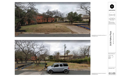
PROGRESS PRINT NOT FOR REGULATORY APPROVAL, PERMIT, OR CONSTRUCTION Copyright: These drawings are property of the architect and may not be reproduced, distributed, published, or used in any way without written consent of the architect. l a z a P a m a P 8 1 6 1 l 3 0 7 8 7 X T , n i t s u A l , a z a P a m a P 8 1 6 1 l Design Development August 5, 2022 Drawn by: CC, XH Checked by: CC Revisions: Existing Site Photos Existing Site View from Palma Plaza, south corner of site looking northwest Existing Site View from Palma Plaza, east corner of site looking northwest G1.03 PROGRESS PRINT NOT FOR REGULATORY APPROVAL, PERMIT, OR CONSTRUCTION Copyright: These drawings are property of the architect and may not be reproduced, distributed, published, or used in any way without written consent of the architect. l a z a P a m a P 8 1 6 1 l 3 0 7 8 7 X T , n i t s u A l , a z a P a m a P 8 1 6 1 l Design Development August 5, 2022 Drawn by: CC, XH Checked by: CC Revisions: Project Rendering G1.04 559' Unit C Proposed Gas & Elec. meters UP DN 558.75 UNIT C 555.58 " 3 ' - 0 2 Egress well & steps 556.58 558.90 1 8 ' - 0 " (2) Parking Spaces in Private Garage Unit B Proposed Gas & Elec. meters Unit B Proposed HVAC 1 3 . 0 A / 2 1021 550 Unit C Proposed HVAC 50% CRZ Unit A Proposed Gas & Elec. meters Building overhangs 50% CRZ above Unit A Proposed HVAC 2 / A 3 . 0 2 1022 5 5 8 ' UNIT B 556.83 2 0 ' - 9 " UNIT A 554.08 554.00 (2) Parking Spaces in Private Garage 554.00 " 8 ' - 0 1 553.87 5 5 5' DN Gate 5 5 6' See G1.11 for continued Accessible Route UP 5 5 7 ' 1 3 . 0 A / 1 a z a l m a P l a P 5 5 7 ' Proposed Detention Pond 5 5 6 ' 1030 1028 1027 1029 1024 1025 1026 1023 1 / A 3 . 0 2 1018 Retaining wall " 2 / 4 ' - 1 1 2 " 0 0 ' - 1 2 556.67 1 8 ' - 0 " (2) Parking Spaces in Private Garage 556.75 Gate 557.75 " 7 ' - 9 1 k i n r a ) P 1 ( 8 ' - 8 " e c a p g S 561.25 558.30 2 1 : 1 560.08 2 1 : 1 0 1 : 2 558' 8 ' - 0 " 1015 5 5 7' 1 0 . 0 % 5 5 8' 1 . 8 % " 4 ' - 0 8 ' - 6 " " s c a 1 7 ' - 6 e c c n A a g S k i n p 1 ( ) V r a P s i b l e e 4 ' - 0 " Accessible Route sidewalk 1033 Construction Type: Occupancy Type: Total Gross Floor Area: V-B R-3 + U Private Garage 10,112 SF Copyright: These drawings are property of the architect and may not be reproduced, distributed, published, or used in any way without written consent of the architect. LEGEND Property Line Existing Asphalt Limit of Construction Impervious Cover Existing Fence New stone paving Area to be demolished New concrete Existing Buildings Vegetation Existing Concrete Existing trees to be removed. Existing Trees to remain. SITE PROGRAM UNIT A # Bedrooms: Gross Floor Area: Building Fire Area: Grade Plane: Lvl 1 (first story above grade): Lvl 1 height above grade plane: Building Height: UNIT B # Bedrooms: Gross Floor Area: Building Fire Area: Grade Plane: Lvl 1 (first story above grade): Lvl 1 height above grade plane: Building Height: UNIT C # Bedrooms: Gross Floor Area: Building Fire Area: Grade Plane: Lvl 1 (first story above grade): Lvl 1 height above grade plane: Building Height: 3 Bedroom 3,293 SF 3,905 SF 558.51' 564.00' 5.49 FT 40 FT 3 Bedroom 3,251 SF 3,810 SF 560.31' 565.92' 5.61 FT 40 FT 4 Bedroom 3,568 SF 4,104 SF 559.56' 564.92' 5.36 FT 40 FT SITE PLAN NOTES KEYNOTES l a z a P a m a P 8 1 6 1 l 3 0 7 8 7 X T , n i t s u A l , a z a P a m a P 8 1 6 1 l Design Development August 5, 2022 Drawn by: CC, XH Checked by: CC Revisions: Architectural Reference Site Plan - Garage Level G1.10 N 1 Site Plan - Garage Level 1" = 10'-0" 1 3 . 0 A / 2 1021 550 559' DN See G1.10 for lower grade conditions UNIT C 565.25 Accessible Unit Entrance 566.12 565.18 a m p D n R Accessible Unit Entrance UNIT B 1022 5 5 8 ' S l o p 1 e : 2 D 3 n " 0 ' - 2 1 566.17 S l o 1 : p e 2 0 D n Accessible Unit Entrance 564.25 UNIT A 564.25 50% CRZ Building overhangs 50% CRZ without impacting grade at this location. See G1.10 for building footprint at ground level. 2 / A 3 . 0 2 5 5 7 ' See G1.10 for lower grade conditions 5 5 5' Proposed Detention Pond 5 5 6' 5 5 6 ' 1030 1028 1027 1029 1024 1025 1026 1023 a m p D n 2 1 : 1 R n a m p D 1 : 1 2 R 0 1 : 2 558' 5 5 7 ' 1 3 . 0 A / 1 a z a l m a P l a P 1 / A 3 . 0 2 1018 5 5 7' 558.38 1015 See G1.10 for lower grade conditions 8' 5 5 1033 Construction Type: Occupancy Type: Total Gross Floor Area: V-B R-3 + U Private Garage 10,112 SF Copyright: These drawings are property of the architect and may not be reproduced, distributed, published, or used in any way without written consent of the architect. LEGEND Property Line Existing Asphalt Limit of Construction Impervious Cover Existing Fence New stone paving Area to be demolished New concrete Existing Buildings Vegetation Existing Concrete Existing trees to be removed. Existing Trees to remain. SITE PROGRAM UNIT A # Bedrooms: Gross Floor Area: Building Fire Area: Grade Plane: Lvl 1 (first story above grade): Lvl 1 height above grade plane: Building Height: UNIT B # Bedrooms: Gross Floor Area: Building Fire Area: Grade Plane: Lvl 1 (first story above grade): Lvl 1 height above grade plane: Building Height: UNIT C # Bedrooms: Gross Floor Area: Building Fire Area: Grade Plane: Lvl 1 (first story above grade): Lvl 1 height above grade plane: Building Height: 3 Bedroom 3,293 SF 3,905 SF 558.51' 564.00' 5.49 FT 40 FT 3 Bedroom 3,251 SF 3,810 SF 560.31' 565.92' 5.61 FT 40 FT 4 Bedroom 3,568 SF 4,104 SF 559.56' 564.92' 5.36 FT 40 FT SITE PLAN NOTES KEYNOTES l a z a P a m a P 8 1 6 1 l 3 0 7 8 7 X T , n i t s u A l , a z a P a m a P 8 1 6 1 l Design Development August 5, 2022 Drawn by: CC, XH Checked by: CC Revisions: Architectural Reference Site Plan - Level 1 G1.11 N 1 Site Plan - Level 1 1" = 10'-0" " 1 1 - ' 1 " 3 - ' 8 " 4 / 3 2 - ' 9 " 4 / 1 9 - ' 4 " 2 / 1 6 . a 2 0 3 A / 1 . a 2 0 3 A / 1 " 4 / 1 0 1 - ' 1 " 8 / 5 3 - ' 8 " 8 / 1 0 - ' 4 1 " 2 / 1 6 Q P 2/A3.02a L K KEYNOTES 6 1/8" 5' - 3 1/2" 8' - 3" 13' - 1" 7' - 3" CL 2' - 10 1/2" 19' - 3 1/2" 20' - 4" 6' - 7 1/2" 6 1/8" 8' - 8 1/2" 10" 2 A5.01a CL W112 N 1 a 1 0 . 4 A M 53' - 5 1/2" 8' - 1 3/4" 6' - 0 1/2" Clo. A-106 CL W111 W110 106 " 2 / 1 4 - ' 1 " 4 / 1 8 - ' 2 " 7 - ' 3 7 0 1 Powder A-105 5 0 1 DN UP Stair A 9 0 1 Elev. A 5' - 4 3/4" 3' - 10" 20' - 4 5/8" 3' - 10 5/8" 6' - 2 3/4" Vestibule A-107 Living Room A-101 Dining A-102 " 4 / 1 0 1 - ' 4 " 2 / 1 9 - ' 3 " 8 - ' 5 " 8 / 7 9 - ' 3 CL 3 1 1 W 4 1 1 W 2' - 5" Pantry A-104 1 0 4 Kitchen A-103 " 8 / 7 0 - ' 4 " 6 - ' 7 " 8 / 5 8 - ' 3 CL 9 0 1 W 7' - 7 1/8" 5' - 6" W108 W107 W106 W105 W104 W103 W102 1 0 1 W101 5' - 3 1/2" 2' - 1 1/8" 3' - 0 3/8" 3' - 0" 3' - 0" 3' - 0" 3' - 0" 3' - 0 3/8" 2' - 1 1/8" 3' - 6 3/4" 6' - 1" 6' - 1" 3' - 6 3/4" 6' - 7 1/2" 10" CL CL CL CL CL CL CL CL 2/A3.01a 2 UNIT A - Floor Plan - Level 1 1/4" = 1'-0" Q P 2/A3.02a L K 6 1/8" 5' - 3 1/2" 13' - 1" 8' - 3 5/8" 20' - 10 1/8" N 1 a 1 0 . 4 A M 53' - 5 1/2" 8' - 1 3/4" 19' - 3 1/2" 15' - 7 1/4" 6' - 7 1/2" 6 1/8" 8' - 8 1/2" 6 3/8" CL W001 1 A5.01a 007 8' - 4 3/4" 5' - 0" 1' - 7 7/8" 3' - 4 3/4" 5 0 0 5' - 2 1/4" Hall A-007 UP Stair A 9 0 0 Elev. A Storage A-005 006 HVAC A-006 " 8 / 3 9 - ' 7 " 8 / 3 7 - ' 2 " 4 / 3 4 - ' 5 002b " 4 / 3 1 - ' 1 Guest Bath 1 A-003 3 0 0 002a 004 Closet A-004 Guest Bed 1 A-002 " 8 / 3 0 1 - ' 5 " 4 / 3 6 - ' 2 " 2 / 1 6 - ' 1 1 " 2 / 1 3 Garage A-001 001 CL 5' - 3 1/2" 11' - 1 1/2" 11' - 1 1/2" 6' - 6 3/4" 3' - 1" 9' - 7 3/4" 6' - 7 1/2" 6 3/8" CL CL 2/A3.01a 1 UNIT A - Floor Plan - Level 0 1/4" = 1'-0" FLOOR PLAN NOTES 1. 2. 3. 4. Refer to sheet G2.1 for wall types and partition types. Refer to G2.4, G2.6, G2.7, G2.8 for window types and schedule. Refer to sheet 2.4 and G2.5 for door and frame types and schedules. Refer to Sheet G2.2, G2.3 for finish schedule, appliance schedule, plumbing fixture schedule, bath accessory schedule. Floor Plans - Unit A - Garage & Level 1 A1.01a " 8 / 1 6 " 1 1 - ' 1 " 6 1 / 7 7 - ' 7 " 4 / 1 7 - ' 8 " 0 - ' 5 CL CL " 2 / 1 8 - ' 4 2 " 2 / 1 6 " 8 / 1 6 " 8 / 1 0 1 - ' 1 " 8 / 7 9 - ' 1 " 8 / 1 3 - ' 7 " 4 / 1 9 - ' 5 " 8 / 5 5 - ' 2 " 0 - ' 5 " 2 / 1 6 " 8 / 1 6 " 1 1 - ' 1 " 2 / 1 7 - ' 7 " 4 / 1 7 - ' 8 " 0 - ' 5 " 2 / 1 8 - ' 4 2 " 2 / 1 9 - ' 4 1 " 8 / 3 4 - ' 4 " 0 - ' 5 " 2 / 1 6 " 2 / 1 6 " 8 / 1 6 10 11 12 2 A4.01a . a 1 0 3 A / 1 13 13.9 14 10 11 12 2 A4.01a . a 1 0 3 A / 1 13 13.9 14 PROGRESS PRINT NOT FOR REGULATORY APPROVAL, PERMIT, OR CONSTRUCTION Copyright: These drawings are property of the architect and may not be reproduced, distributed, published, or used in any way without written consent of the architect. l a z a P a m a P 8 1 6 1 l 3 0 7 8 7 X T , n i t s u A l , a z a P a m a P 8 1 6 1 l Design Development August 5, 2022 Drawn by: CC, XH Checked by: CC Revisions: KEYNOTES FLOOR PLAN NOTES 1. 2. 3. 4. Refer to sheet G2.01 for wall types and partition types. Refer to G2.X for window types and schedule. Refer to sheet 2.X for door and frame types and schedules. Refer to Sheet G2.X for finish schedule, appliance schedule, plumbing fixture schedule, bath accessory schedule. PROGRESS PRINT NOT FOR REGULATORY APPROVAL, PERMIT, OR CONSTRUCTION Copyright: These drawings are property of the architect and may not be reproduced, distributed, published, or used in any way without written consent of the architect. l a z a P a m a P 8 1 6 1 l 3 0 7 8 7 X T , n i t s u A l , a z a P a m a P 8 1 6 1 l " 2 / 1 0 1 - ' 5 " 4 / 1 5 - ' 3 1 " 4 - ' 1 1 " 8 / 1 6 " 2 / 1 0 1 - ' 5 " 4 / 1 7 - ' 9 " 4 / 3 7 - ' 0 3 CL " 4 / 1 7 - ' 8 " 0 - ' 5 " 2 / 1 6 " 8 / 1 6 05 06 . b 1 0 3 A / 1 08 08.9 09 Floor Plans - Unit B - Garage & Level 1 1 UNIT B - Floor Plan - Level 0 1/4" = 1'-0" A1.01b " 4 / 3 5 - ' 3 R 2 ' - 3 1 / 8 " 1 A5.01b Elev. B 007 4' - 1 1/4" 9' - 1 1/4" 4' - 6 1/2" HVAC B-005 5 0 0 " 4 / 3 2 - ' 4 Hall B-006 8' - 6 1/8" 6 0 0 002b 1' - 6" 1' - 8 1/4" Closet B-004 004 3 0 0 Guest Bath 1 B-003 9 3/8" " 4 / 1 9 - ' 7 1 Guest Bed 1 B-002 5' - 10 3/4" 12' - 10 7/8" 20' - 11 1/4" Garage B-001 1 0 0 07 Design Development August 5, 2022 Drawn by: CC, XH Checked by: CC Revisions: 42' - 9" Stair B DN 002a J H G 1 b 1 0 . 4 A F E J H G 2 b 1 0 . 4 A 1 b 1 0 . 4 A F E 6 1/8" 10" 6' - 7 1/2" CL 4' - 3 1/4" 4' - 6" 4' - 6" 5' - 10 1/2" 9' - 11 1/4" 7' - 1 1/8" 4' - 6 1/2" CL CL 2' - 0 3/8" 42' - 9" 18' - 5 1/2" 12' - 1 1/4" 4' - 6 1/2" 6 1/8" CL W109 6 1/8" 6 3/8" 6' - 7 1/2" 15' - 3 1/2" 18' - 5 1/2" 5' - 7 7/8" 12' - 1 1/4" 4' - 6 1/2" 6 1/8" 17' - 3 1/8" 4' - 6 1/2" 2 b 1 0 . 4 A 102 W107 W108 . b 2 0 3 A / 1 Living Room B-101 10' - 0 1/2" 5' - 2" 106 Clo. B-106 Powder 1 B-105 5 0 1 Stair B R 2' - 1 7/8" 2 A5.01b Pantry B-104 " 4 / 1 2 - ' 4 104 4' - 5 5/8" Elev. B 109 Vestibule B-107 107 CL Dining B-102 Kitchen B-103 1 0 1 W106 W105 W104 W103 W102 W101 " 2 / 1 0 1 - ' 5 " 8 / 7 8 - ' 6 " 4 / 1 9 - ' 5 " 8 / 5 8 - ' 6 " 0 - ' 5 " 2 / 1 6 " 8 / 1 6 " 2 / 1 0 1 - ' 5 " 4 / 1 7 - ' 9 CL " 4 / 1 7 - ' 8 " 2 / 1 6 - ' 5 CL " 4 / 3 7 - ' 0 3 " 2 / 1 0 1 - ' 5 " 8 / 1 3 - ' 7 " 8 / 1 1 1 - ' 7 " 2 / 1 " 6 2 / - 1 ' 3 9 " 6 - ' 2 0 1 1 W 1 1 1 W " 8 / 7 4 " 4 / 1 4 - ' 2 " 8 / 1 6 05 06 . b 2 0 3 A / 1 07 . b 1 0 3 A / 1 08 08.9 09 " 2 / 1 0 1 - ' 5 " 8 / 7 0 1 - ' 6 " 8 / 1 7 - ' 5 " 4 / 3 8 - ' 6 " 0 - ' 5 " 2 / 1 6 2 UNIT B - Floor Plan - Level 1 1/4" = 1'-0" 10" 6' - 7 1/2" 3' - 6 3/4" 5' - 8" 5' - 8" 3' - 6 3/4" 4' - 3 1/8" 2' - 6" 4' - 0" 4' - 0" 2' - 4 3/4" 6 1/8" 6 3/8" 6' - 7 1/2" 9' - 7 1/2" 2' - 6" 4' - 3 1/4" 2' - 0 3/4" 17' - 8" CL CL CL CL CL CL 2/A3.01b CL CL 2/A3.01b 3/A3.03c 15' - 8 1/4" 33' - 9 7/8" 32' - 9 5/8" CL W 104 10' - 0" CL W 105 8' - 1 5/8" Kitchen C-103 1 c 1 0 . 4 A A 6 1/8" 6 1 / 8 " 01 4' - 0 3 / 8 " C L W 1 0 3 4' - 1 0 3 / 4 " 2 / A 3 . 0 2 c 2 2 4' - 9 1 3' - 9 1 / 2 " / 4 " C L W 1 0 2 Powder 1 C-105 1 3' - 2 7 / 8 " Pantry C-104 1 0 4 4' - 9 " 2' - 4 3 / 4 " Clo. C-107 5' - 8 1/8" 107 1 0 5 3' - 8 7/8" 1 0 6 3' - 1 0 3 / 4 " DN Hall 1 C-106 3' - 5 3 / 4 " 1 0 9 4' - 6 3 / 4 " Stair C Elev. C 3' - 7 3 / 4 " Dining C-102 B 6 1/8" " 8 / 3 9 - ' 6 " 4 / 1 3 - ' 7 1 " 8 / 1 6 2 / A 3 . 0 3 c 2 A4.01c 01 03 04 7' - 1 " W 1 0 6 C L 7 0 1 W 8 0 1 W 9 0 1 W CL " 8 / 3 9 - ' 4 " 8 / 3 9 - ' 4 " 0 - ' 4 CL CL . c 2 0 3 A / 1 Living Room C-101 101 1' - 8 1/8" CL 1' - 4" 1' - 5" 8' - 0 1/8" 1' - 5" 1' - 4" 9' - 4 7/8" 24' - 7" C L 02 W 1 0 1 6 1 / 2' - 7 1 8 " / 2 " 2 A5.01c A 1/A3.03c 03 11' - 10 1/4" 13' - 7 7/8" W 112 1 1 1 W CL CL 0 1 1 W CL " 2 - ' 1 1 " 2 / 1 0 1 - ' 4 " 1 " 4 / 1 3 - ' 7 1 . c 1 0 3 A / 1 04 2 UNIT C - Floor Plan - Level 1 1/4" = 1'-0" KEYNOTES FLOOR PLAN NOTES 1. 2. 3. 4. Refer to sheet G2.1 for wall types and partition types. Refer to G2.4, G2.6, G2.7, G2.8 for window types and schedule. Refer to sheet 2.4 and G2.5 for door and frame types and schedules. Refer to Sheet G2.2, G2.3 for finish schedule, appliance schedule, plumbing fixture schedule, bath accessory schedule. 1 c 1 0 . 4 A A 6 1/8" 6 1 / 8 " 01 8' - 5" CL W 003 3/A3.03c 7' - 3 1/4" W 004 3' - 1" HVAC C-009 009 9' - 4 " 2 / A 3 . 0 2 c C L W 0 0 2 2 2 4' - 9 1 3' - 9 1 / 2 " / 4 " 1 2' - 1 0 " Guest Bath 1 C-003 Laundry C-005 5' - 11 1/4" 008 Storage C-008 3' - 7 3/4" 3' - 5 3 / 4 " 33' - 9 7/8" 32' - 9 5/8" CL 10' - 0" CL W 005 8' - 1 5/8" 0 0 2 b 0 0 4 Closet C-004 5' - 1 0 1 / 4 " 003 0 0 5 1' - 9 " 0 0 2 a 5' - 5 1 / 2 " Guest Bed 1 C-002 Hall C-006 4' - 6 3 / 4 " Elev. C UP Stair C 010 0 0 7 3' - 7 3 / 4 " C L 02 6 1 / 8 " 2' - 7 1 / 2 " W 0 0 1 CL 3' - 1 1/4" 1 0' - 1 1 / 2 " 0 0 6 10' - 10 1/4" 1 A5.01c " 2 - ' 3 1 PROGRESS PRINT NOT FOR REGULATORY APPROVAL, PERMIT, OR CONSTRUCTION Copyright: These drawings are property of the architect and may not be reproduced, distributed, published, or used in any way without written consent of the architect. l a z a P a m a P 8 1 6 1 l 3 0 7 8 7 X T , n i t s u A l , a z a P a m a P 8 1 6 1 l A 1/A3.03c 03 04 " 8 / 1 6 - ' 1 " 8 / 3 0 - ' 9 " 8 / 3 0 - ' 9 " 8 / 1 5 - ' 1 Garage C-001 001 CL Design Development August 5, 2022 Drawn by: CC, XH Checked by: CC Revisions: " 4 / 1 3 - ' 7 1 . c 1 0 3 A / 1 23' - 6 3/4" Floor Plans - Unit C - Garage & Level 1 1 UNIT C - Floor Plan - Level 0 1/4" = 1'-0" A1.01c B 6 1/8" 2' - 7 " C L 2 / A 3 . 0 3 c 2 A4.01c . c 2 0 3 A / 1 D 2/A3.01c C D 2/A3.01c C Q P 5' - 3 1/2" 13' - 1" N 1 a 1 0 . 4 A M 44' - 0 1/2" 2/A3.02a L K KEYNOTES 9' - 9 3/4" Powder 2 A-303 8' - 1 3/4" CL 5' - 7 3/8" W303 Bev. 2 0 3 Wet Bar A-302 5' - 9 3/4" 5' - 6 5/8" W301 CL 2 0 3 W Pool A 19' - 3 1/2" 20' - 4" 6' - 7 1/2" 1" 8' - 3 3/8" CL W304 4 A5.01a Stair A 304 Elev. A Terrace Living A-301 3 0 3 HVAC A-304 TV 305 CL Terrace A-305 9' - 9 3/4" 15' - 4 7/8" 16' - 9 1/4" Equipment 2' - 9 1/4" 2/A3.01a N 1 a 1 0 . 4 A M 54' - 3 1/2" Grill 8' - 1 3/4" CL W213 Toilet A-204 1' - 8 3/8" 4' - 6 1/4" 201 Q P 2/A3.02a L K 6 1/8" 5' - 3 1/2" 8' - 3" 13' - 1" 7' - 2" CL 2' - 11 1/2" 6' - 0 1/2" 19' - 3 1/2" 20' - 4" 6' - 7 1/2" 8' - 8 1/2" CL W214 6 1/8" 10" 3 A5.01a W212 203a 5' - 10 7/8" Primary Bathroom A-203 203b 7' - 10 1/4" 4 0 2 8' - 5 3/4" 1' - 8 3/8" 3' - 7 1/4" 5' - 10 3/4" 1 1 2 W 0 1 2 W Align 7' - 10 1/4" 203c 202 " 8 / 1 0 1 - ' 1 16' - 4 3/4" 9' - 6" Primary Bed A-201 Primary Closet A-202 " 8 / 7 7 - ' 2 " 8 / 7 3 - ' 3 1 DN UP Stair A 211 Elev. A Laundry A-208 HVAC A-209 Hall A-210 7' - 3" 209 5' - 6" 205 8 0 2 " 4 / 3 8 - ' 3 " 4 / 3 4 - ' 3 206a 206 1' - 5 1/8" 5' - 4 3/8" " 7 " 4 / 3 9 - ' 2 " 2 / 1 0 - ' 2 1 207 Closet A-207 11' - 10 3/4" Guest Bed 2 A-205 Guest Bath 2 A-206 W201 2 UNIT A - Floor Plan - Level 3 1/4" = 1'-0" " 1 " 1 1 - ' 1 " 2 / 1 8 - ' 9 " 8 - ' 6 " 8 / 3 0 - ' 1 " 8 / 7 8 - ' 1 " 8 / 1 6 " 1 1 - ' 1 " 6 1 / 7 7 - ' 7 " 4 / 1 7 - ' 8 " 0 - ' 5 " 2 / 1 8 - ' 4 2 " 8 / 1 1 - ' 9 " 4 / 1 9 - ' 2 " 2 / 1 3 - ' 7 " 0 - ' 5 " 2 / 1 6 " 2 / 1 6 " 8 / 1 6 10 11 12 2 A4.01a . a 1 0 3 A / 1 13 13.9 14 10 11 12 2 A4.01a . a 1 0 3 A / 1 13 13.9 14 . a 2 0 3 A / 1 . a 2 0 3 A / 1 " 1 1 - ' 1 " 8 / 7 5 - ' 5 " 8 / 5 3 - ' 2 CL " 1 1 - ' 1 " 9 - ' 1 1 " 6 - ' 3 " 8 / 7 5 - ' 6 " 2 / 1 6 CL CL " 8 / 1 6 PROGRESS PRINT NOT FOR REGULATORY APPROVAL, PERMIT, OR CONSTRUCTION Copyright: These drawings are property of the architect and may not be reproduced, distributed, published, or used in any way without written consent of the architect. l a z a P a m a P 8 1 6 1 l 3 0 7 8 7 X T , n i t s u A l , a z a P a m a P 8 1 6 1 l Design Development August 5, 2022 Drawn by: CC, XH Checked by: CC Revisions: W209 W208 W207 W206 W205 W204 W203 W202 5' - 3 1/2" 2' - 1 1/8" 3' - 0 3/8" 3' - 0" 3' - 0" 3' - 0" 3' - 0" 3' - 0 3/8" 2' - 1 1/8" 3' - 6 3/4" 6' - 1" 6' - 1" 3' - 6 3/4" 3' - 3 3/4" 3' - 3 3/4" CL CL CL CL CL CL CL CL CL 2/A3.01a FLOOR PLAN NOTES 1. 2. 3. 4. Refer to sheet G2.1 for wall types and partition types. Refer to G2.4, G2.6, G2.7, G2.8 for window types and schedule. Refer to sheet 2.4 and G2.5 for door and frame types and schedules. Refer to Sheet G2.2, G2.3 for finish schedule, appliance schedule, plumbing fixture schedule, bath accessory schedule. Floor Plan - Unit A - Levels 2 & 3 A1.02a 1 UNIT A - Floor Plan - Level 2 1/4" = 1'-0" KEYNOTES FLOOR PLAN NOTES 1. 2. 3. 4. Refer to sheet G2.01 for wall types and partition types. Refer to G2.X for window types and schedule. Refer to sheet 2.X for door and frame types and schedules. Refer to Sheet G2.X for finish schedule, appliance schedule, plumbing fixture schedule, bath accessory schedule. PROGRESS PRINT NOT FOR REGULATORY APPROVAL, PERMIT, OR CONSTRUCTION Copyright: These drawings are property of the architect and may not be reproduced, distributed, published, or used in any way without written consent of the architect. J H 2 b 1 0 . 4 A G 41' - 8 3/4" 1 b 1 0 . 4 A F E 1" 6' - 7 1/2" 18' - 5 1/2" 4' - 6 1/2" 1" 15' - 2" 5' - 10 1/2" 9' - 7 3/4" 6' - 7" 4' - 7 1/2" 12' - 1 1/4" CL W302 J H 6 1/8" 10" 6' - 7 1/2" 13' - 3 1/8" 2 b 1 0 . 4 A 18' - 5 1/2" CL 2' - 0 3/8" G 41' - 8 3/4" 5' - 10 1/2" 9' - 11 1/4" 7' - 1 1/8" 4' - 6 1/2" 1 b 1 0 . 4 A F E 4' - 6 1/2" 6 1/8" 12' - 1 1/4" CL W210 Stair B 4 A5.01b Elev. B 304 Terrace Living B-302 305 Vest. B-304 HVAC B-306 3 0 3 302 Powder 2 B-305 " 2 / 1 5 - ' 3 " 4 / 3 2 - ' 5 3 0 3 W CL 1 0 3 W Wet Bar 301 16' - 2 1/8" 24' - 2 1/2" Equipment 301 CL Terrace A-307 Pool B 05 06 . b 2 0 3 A / 1 07 " 2 / 1 1 1 - ' 5 " 8 / 7 5 - ' 3 " 8 / 7 2 - ' 4 " 2 / 1 1 1 - ' 1 " 4 / 3 9 08 08.9 09 " 4 / 3 7 - ' 5 1 1' - 3 1/8" CL 8 0 2 W 13' - 6 5/8" 4' - 4 3/4" 2' - 8" 6' - 4 3/4" 4' - 0 1/4" 5' - 5" 201 9 0 2 3' - 6 3/4" HVAC B-209 Stair B 3 A5.01b W209 Guest Bedroom 2 B-205 5 0 2 6 0 2 Closet B-206 Toilet B-204 Hall B-212 " 4 / 3 0 - ' 3 " 3 - ' 5 " 4 / 3 7 " 4 / 3 4 - ' 3 " 4 / 3 5 - ' 6 1' - 3" 7' - 9" Primary Closet B-202 2 0 2 a 3 0 2 207a 207b W207 Guest Bathroom 2 B-207 203b 204 3' - 3" 5' - 0" 5' - 8" Primary Bathroom B-203 Elev. B 211 0 1 2 Laundry B-208 12' - 7" Primary Bedroom B-201 " 4 / 1 9 - ' 5 " 4 / 1 1 1 - ' 6 " 4 / 1 1 1 - ' 2 " 1 " 2 / 1 0 1 - ' 5 " 4 / 1 7 - ' 9 CL " 4 / 1 7 - ' 8 " 0 - ' 5 " 2 / 1 6 05 06 . b 2 0 3 A / 1 07 . b 1 0 3 A / 1 08 08.9 09 " 2 / 1 0 1 - ' 5 " 0 - ' 4 " 8 / 7 2 - ' 4 " 4 / 1 9 - ' 2 " 8 / 5 2 - ' 8 " 0 - ' 5 l a z a P a m a P 8 1 6 1 l 3 0 7 8 7 X T , n i t s u A l , a z a P a m a P 8 1 6 1 l 07 Design Development August 5, 2022 Drawn by: CC, XH Checked by: CC Revisions: " 8 / 1 6 " 2 / 1 0 1 - ' 5 " 4 / 1 7 - ' 9 " 4 / 1 7 - ' 8 " 4 / 3 7 - ' 0 3 " 2 / 1 0 1 - ' 5 " 4 / 1 2 - ' 5 1 " 4 - ' 4 " 6 - ' 2 " 8 / 1 9 - ' 2 1 1 2 W " 0 - ' 5 CL " 2 / 1 6 " 8 / 1 6 05 06 . b 1 0 3 A / 1 08 08.9 09 2/A3.01b CL CL CL CL 2/A3.01b CL CL CL W206 W205 W204 W203 W202 W201 3' - 3 3/4" 3' - 3 3/4" 3' - 6 3/4" 5' - 8" 5' - 8" 3' - 6 3/4" 4' - 3 1/8" 2' - 6" 4' - 0" 4' - 0" 2' - 6" 4 7/8" Floor Plans - Unit B - Levels 2 & 3 2 UNIT B - Floor Plan - Level Terrace 1/4" = 1'-0" 1 UNIT B - Floor Plan - Level 2 1/4" = 1'-0" A1.02b 3/A3.03c 27' - 6" 32' - 11 5/8" 32' - 9 5/8" 1 c 1 0 . 4 A A 1" 01 1 " 3' - 7 1 / 4 " C L W 3 0 4 4' - 8 1 / 2 " 2 / A 3 . 0 2 c C L W 3 0 3 2 2 3' - 1 3' - 9 1 1 1 / 4 " / 4 " 5' - 1 1 / 8 " C L Guest Bedroom 3 C-302 3 0 3 Closet C-303 DN 302 Elev. C Terrace Living C-301 3 0 8 W 3 0 2 Stair C 8' - 4 " C L 02 W 3 0 1 1 " 2' - 2 3 / 8 " 13' - 7 7/8" 4 A5.01c " 2 - ' 3 1 1/A3.03c B 1" 5' - 5 5/8" Equip. C-307 3 0 4 b Guest Bathroom 3 C-304 3 0 7 304a 6' - 1 1 / 8 " 5 0 3 HVAC C-305 3' - 6 " 2 / A 3 . 0 3 c 2 A4.01c . c 2 0 3 A / 1 Pool C 301 Terrace C-306 23' - 6 3/4" " 4 / 1 3 - ' 7 1 . c 1 0 3 A / 1 03 04 KEYNOTES FLOOR PLAN NOTES 1. 2. 3. 4. Refer to sheet G2.1 for wall types and partition types. Refer to G2.4, G2.6, G2.7, G2.8 for window types and schedule. Refer to sheet 2.4 and G2.5 for door and frame types and schedules. Refer to Sheet G2.2, G2.3 for finish schedule, appliance schedule, plumbing fixture schedule, bath accessory schedule. 1 c 1 0 . 4 A A 6 1/8" 6 1 / 8 " 01 3' - 6 1 / 4 " C L W 2 0 2 4' - 8 1 / 2 " 2 / A 3 . 0 2 c C L W 2 0 1 2 4' - 9 1 2 3' - 9 1 / 2 " / 4 " 3/A3.03c 15' - 8 1/4" 33' - 9 7/8" 32' - 9 5/8" CL 10' - 0" W 203 3' - 2 3/4" 4' - 8 1/4" Guest Bath 2 C-205 8' - 5 1 / 4 " 2 0 6 a 2' - 1 0 3 / 4 " 206b Guest Bath 2 C-206 CL W 204 10' - 11 3/4" 8' - 1 5/8" B 6 1/8" 2 / A 3 . 0 3 c 2 A4.01c " 8 / 3 9 - ' 6 " 1 1 - ' 3 CL CL " 0 - ' 4 " 4 / 1 3 - ' 7 1 " 8 / 7 6 - ' 9 . c 2 0 3 A / 1 5 0 2 W 6 0 2 W 3' - 2 1/4" Stair C 207 Closet C-207 Hall 2 C-209 2 0 1 a 208 DN 205 3' - 9 1 / 4 " 5' - 9 1/4" Elev. C 2 1 0 3' - 8 1 / 4 " UP 4' - 6 3/4" 3' - 1 1 1 / 4 " 11' - 10 1/4" 3 A5.01c 2' - 1 1/4" W 210 HVAC C-208 201b a 3 0 2 4 0 2 8' - 6 3/8" 11' - 5 5/8" 3' - 6 3/4" Primary Closet C-202 2 0 2 Primary Bedroom C-201 " 4 / 3 4 - ' 3 " 4 / 1 8 - ' 2 " 4 / 1 7 - ' 3 " 4 / 3 0 - ' 4 1 Primary Bathroom C-203 203b Toilet C-204 9 0 2 W " 8 / 7 7 - ' 1 8 0 2 W 7 0 2 W CL " 8 / 5 3 - ' 3 " 7 - ' 5 " 7 - ' 5 " 8 / 3 5 - ' 4 CL CL CL PROGRESS PRINT NOT FOR REGULATORY APPROVAL, PERMIT, OR CONSTRUCTION Copyright: These drawings are property of the architect and may not be reproduced, distributed, published, or used in any way without written consent of the architect. l a z a P a m a P 8 1 6 1 l 3 0 7 8 7 X T , n i t s u A l , a z a P a m a P 8 1 6 1 l " 4 / 3 9 - ' 6 1 02 6 1 / 8 " 03 " 2 - ' 3 1 1/A3.03c Design Development August 5, 2022 Drawn by: CC, XH Checked by: CC Revisions: " 4 / 1 3 - ' 7 1 . c 1 0 3 A / 1 04 " 1 " 8 / 1 5 Floor Plans - Unit C - Levels 2 & 3 D C 2 UNIT C - Floor Plan - Level Terrace 1/4" = 1'-0" 1' - 4" 6 1/8" D 1' - 5" 9' - 8 1/4" 1' - 5" 1' - 4" 9' - 4 7/8" 23' - 6 3/4" 24' - 7" 6 1/8" 2/A3.01c C 1 UNIT C - Floor Plan - Level 2 1/4" = 1'-0" A1.02c Q P N 1 a 1 0 . 4 A M 2/A3.02a L K KEYNOTES 1/4" / 1'-0" 1/4" / 1'-0" 1/4" / 1'-0" 1/4" / 1'-0" D.S. " 0 - ' 1 / " 4 / 1 D.S. " 0 - ' 1 / " 4 / 1 Membrane roofing . a 2 0 3 A / 1 2 A4.01a Chimney . a 1 0 3 A / 1 Wood and steel shade structure 10 11 12 13 13.9 14 10 11 12 13 13.9 14 ROOF PLAN NOTES 1. 2. 3. 4. Refer to sheet G2.01 for wall types and partition types. Refer to G2.X for window types and schedule. Refer to sheet G2.X for door and frame types and schedules. Refer to Sheet G2.X for finish schedule, appliance schedule, plumbing fixture schedule, bath accessory schedule. PROGRESS PRINT NOT FOR REGULATORY APPROVAL, PERMIT, OR CONSTRUCTION Copyright: These drawings are property of the architect and may not be reproduced, distributed, published, or used in any way without written consent of the architect. l a z a P a m a P 8 1 6 1 l 3 0 7 8 7 X T , n i t s u A l , a z a P a m a P 8 1 6 1 l Design Development August 5, 2022 Drawn by: CC, XH Checked by: CC Revisions: Roof Plan - Unit A A1.03a 2/A3.01a 2 UNIT A - Roof Plan 1/4" = 1'-0" Q P N M L K 1 a 1 0 . 4 A D.S. D.S. Roof scupper, conductor, and downspout Concrete topping slab at pool and planters. Surface trenches at 16" o.c. 2% to drain PVC drainage pipe below topping slab 1/4" / 1'-0" 1 / 4 " / 1'- 0 " " 3 1/4" / 1'-0" " 7 " 7 2 A4.01a 7" 2 A5.07a -0' - 4" F.F. -1' - 5 1/2" F.F. 1/4" / 1'-0" R.D./O.D. 1/4" / 1'-0" " 0 - ' 1 / " 4 / 1 -0' - 4" F.F. Concrete Topping Slab Membrane roofing 1 UNIT A - Roof Terrace Plan 1/4" = 1'-0" J H G 2 b 1 0 . 4 A 1 b 1 0 . 4 A F E KEYNOTES 1/4" / 1'-0" 1/4" / 1'-0" D.S. " 0 - ' 1 / " 4 / 1 1/4" / 1'-0" 1/4" / 1'-0" . b 2 0 3 A / 1 Membrane roofing Chimney Wood and steel shade structure D.S. " 0 - ' 1 / " 4 / 1 D.S. J H 2 b 1 0 . 4 A 2 UNIT B - Roof Plan 1/4" = 1'-0" 2/A3.01b G 1 b 1 0 . 4 A F D.S. E ROOF PLAN NOTES 1. 2. 3. 4. Refer to sheet G2.01 for wall types and partition types. Refer to G2.X for window types and schedule. Refer to sheet G2.X for door and frame types and schedules. Refer to Sheet G2.X for finish schedule, appliance schedule, plumbing fixture schedule, bath accessory schedule. R.D./O.D. -1' - 0 3/4" 1/4" / 1'-0" 1/4" / 1'-0" Concrete Topping Slab -0' - 4" F.F. " 0 - ' 1 / " 4 / 1 -0' - 4" F.F. 7" Membrane roofing 2 A5.07b Concrete topping slab at pool . Surface trenches at 16" o.c. 2% to drain " 3 " 7 1 UNIT B - Roof Terrace Plan 1/4" = 1'-0" . b 1 0 3 A / 1 08 08.9 09 05 06 07 05 06 07 08 08.9 09 PROGRESS PRINT NOT FOR REGULATORY APPROVAL, PERMIT, OR CONSTRUCTION Copyright: These drawings are property of the architect and may not be reproduced, distributed, published, or used in any way without written consent of the architect. l a z a P a m a P 8 1 6 1 l 3 0 7 8 7 X T , n i t s u A l , a z a P a m a P 8 1 6 1 l Design Development August 5, 2022 Drawn by: CC, XH Checked by: CC Revisions: Roof Plan - Unit B A1.03b 1 c 1 0 . 4 A A 01 D.S. 1/4" / 1'-0" 1/4" / 1'-0" 1 / 4 " / 1'- 0 " D.S. 1/4" / 1'-0" B D.S. 2 A4.01c A 01 1 c 1 0 . 4 A D.S. 02 B 01 1 / 4 " / 1'- 0 " -0' - 4" Membrane roofing Wood and steel shade structure 03 04 " 3 1/4" / 1'-0" -1' - 1 1/2" R.D./O.D. 1/4" / 1'-0" 2 A5.07c 2 A4.01c -0' - 4" F.F. 7" " 0 - ' 1 / " 4 / 1 PVC drainage pipe below topping slab Concrete topping slab at pool . Surface trenches at 16" o.c. 2% to drain Membrane roofing " 7 02 A 03 04 D C D C 2 UNIT C - Roof Plan 1/4" = 1'-0" 1 UNIT C - Roof Terrace Plan 1/4" = 1'-0" KEYNOTES ROOF PLAN NOTES 1. 2. 3. 4. Refer to sheet G2.01 for wall types and partition types. Refer to G2.X for window types and schedule. Refer to sheet G2.X for door and frame types and schedules. Refer to Sheet G2.X for finish schedule, appliance schedule, plumbing fixture schedule, bath accessory schedule. PROGRESS PRINT NOT FOR REGULATORY APPROVAL, PERMIT, OR CONSTRUCTION Copyright: These drawings are property of the architect and may not be reproduced, distributed, published, or used in any way without written consent of the architect. l a z a P a m a P 8 1 6 1 l 3 0 7 8 7 X T , n i t s u A l , a z a P a m a P 8 1 6 1 l Design Development August 5, 2022 Drawn by: CC, XH Checked by: CC Revisions: Roof Plan - Unit C A1.03c 1 a 1 0 . 4 A a 1 0 . 4 A 2 " 0 - ' 3 " 0 - ' 3 PROGRESS PRINT NOT FOR REGULATORY APPROVAL, PERMIT, OR CONSTRUCTION Copyright: These drawings are property of the architect and may not be reproduced, distributed, published, or used in any way without written consent of the architect. l a z a P a m a P 8 1 6 1 l 3 0 7 8 7 X T , n i t s u A l , a z a P a m a P 8 1 6 1 l Design Development August 5, 2022 Drawn by: CC, XH Checked by: CC Revisions: Exterior Elevations - Unit A - South & East A3.01a " 2 / 1 8 - ' 9 3 i t h g e H g n d i l i u B d e s o p o r P A t i n U " 0 - ' 0 4 i t h g e H g d B e b a w o l l l l A . x a M Wood slat equipment screen Steel and wood slatted shade structure (not waterproof) Chimney 598' - 6 1/8" A-Max Bldg Height 598' - 2 5/8" Unit A Top of Parapet 595' - 8 5/8" A-Roof Top Plate Steel guardrail Downspout Standing seam metal wall finish Brick wall finish 587' - 8 1/4" A-3 FF Steel awning 575' - 11 1/4" A-2 FF Steel guardrail 564' - 11" Highest Adjacent Grade - Unit A 564' - 3" A-1 FF First Floor Above Grade " 8 / 7 8 - ' 5 558' - 6 1/8" Average Grade Plane @ Unit A 554' - 1" A-0 T.O. Slab @ Bedroom 554' - 0" A-0 T.O. Slab @ Garage 553' - 11" Lowest Adjacent Grade - Unit A 1 East Elevation - Unit A 1/4" = 1'-0" Chimney Steel and wood slatted shade structure (not waterproof) 598' - 6 1/8" A-Max Bldg Height 598' - 2 5/8" Unit A Top of Parapet 595' - 8 5/8" A-Roof Top Plate Standing seam metal wall finish Steel guardrail 587' - 8 1/4" A-3 FF Metal panel wall finish Brick wall finish 575' - 11 1/4" A-2 FF 564' - 11" Highest Adjacent Grade - Unit A 564' - 3" A-1 FF First Floor Above Grade Steel awning Garage Door 558' - 6 1/8" Average Grade Plane @ Unit A Wooden fence 554' - 1" A-0 T.O. Slab @ Bedroom 554' - 0" A-0 T.O. Slab @ Garage 553' - 11" Lowest Adjacent Grade - Unit A 2 South Elevation - Unit A 1/4" = 1'-0" " 2 / 1 8 - ' 9 3 i t h g e H g n d i l i l u B e b a w o l l A . x a M " 0 - ' 0 4 i t h g e H g n d i l i u B d e s o p o r P A t i n U " 8 / 7 8 - ' 5 2 b 1 0 . 4 A 1 b 1 0 . 4 A 1 0 . 4 A 1 " 0 - ' 3 " 0 - ' 3 Glass railing Steel and wood slatted shade structure (not waterproof) Chimney 600' - 3 23/32" B-Max Bldg Height 600' - 1 5/8" Unit B Top of Parapet 597' - 7 5/8" B-Roof Top Plate Standing seam metal wall finish Steel guardrail Brick wall finish 589' - 7 1/4" B-3 FF Metal panel wall finish " 0 - ' 0 4 " 8 / 7 9 - ' 9 3 i t h g e H g n d i l i l u B e b a w o l l A x a M i t h g e H g n d i l i u B d e s o p o r P B t i n U 577' - 10 1/4" B-2 FF " 4 / 1 0 1 - ' 5 Steel awning Steel guardrail 566' - 2" B-1 FF First Floor Above Grade 565' - 9" Highest Adjacent Grade - Unit B 560' - 3 23/32" Average Grade Plane @ Unit B 556' - 10" B-0 T.O. Slab @ Bedroom 556' - 9" B-0 T.O. Slab @ Garage 556' - 8" Lowest Adjacent Grade - Unit B 2 South Elevation - Unit B 1/4" = 1'-0" PROGRESS PRINT NOT FOR REGULATORY APPROVAL, PERMIT, OR CONSTRUCTION Copyright: These drawings are property of the architect and may not be reproduced, distributed, published, or used in any way without written consent of the architect. l a z a P a m a P 8 1 6 1 l 3 0 7 8 7 X T , n i t s u A l , a z a P a m a P 8 1 6 1 l Design Development August 5, 2022 Drawn by: CC, XH Checked by: CC Revisions: Exterior Elevations - Unit B - South & East Wood slat equipment screen Steel and wood slatted shade structure (not waterproof) Chimney 600' - 3 23/32" B-Max Bldg Height 600' - 1 5/8" Unit B Top of Parapet 597' - 7 5/8" B-Roof Top Plate Glass railing beyond Standing Seam metal wall finish 589' - 7 1/4" B-3 FF Metal panel wall finish Brick wall finish Downspout 577' - 10 1/4" B-2 FF Steel awning 566' - 2" B-1 FF First Floor Above Grade 565' - 9" Highest Adjacent Grade - Unit B Garage Door Concrete retaining wall 560' - 3 23/32" Average Grade Plane @ Unit B " 4 / 1 0 1 - ' 5 556' - 10" B-0 T.O. Slab @ Bedroom 556' - 9" B-0 T.O. Slab @ Garage 556' - 8" Lowest Adjacent Grade - Unit B " 8 / 7 9 - ' 9 3 i t h g e H g n d i l i u B d e s o p o r P B t i n U " 0 - ' 0 4 i t h g e H g n d i l i l u B e b a w o l l A . x a M 1 East Elevation - Unit B 1/4" = 1'-0" A3.01b 1 c 1 0 . 4 A Steel and wood slatted shade structure (not waterproof) Standing seam metal wall finish Glass railing 599' - 7 3/16" C-Max Bldg Height 599' - 2 5/8" Unit C Top of Parapet 596' - 8 5/8" C-Roof Top Plate Steel guardrail 588' - 8 1/4" C-3 FF Metal panel wall finish Brick wall finish Steel awning 576' - 11 1/4" C-2 FF Concrete retaining wall Steel guardrail 565' - 3" C-1 FF First Floor Above Grade 565' - 2" Highest Adjacent Grade - Unit C Egress well beyond 559' - 7 3/16" Average Grade Plane @ Unit C 555' - 7" C-0 T.O. Slab @ Bedroom 555' - 6" C-0 T.O. Slab @ Garage 555' - 5" Lowest Adjacent Grade - Unit C 2 South Elevation - Unit C 1/4" = 1'-0" " 0 - ' 0 4 " 8 / 3 7 - ' 9 3 i t h g e H g n d i l i l u B e b a w o l l A . x a M i t h g e H g n d i l i u B d e s o p o r P C t i n U " 4 / 3 7 - ' 5 PROGRESS PRINT NOT FOR REGULATORY APPROVAL, PERMIT, OR CONSTRUCTION Copyright: These drawings are property of the architect and may not be reproduced, distributed, published, or used in any way without written consent of the architect. l a z a P a m a P 8 1 6 1 l 3 0 7 8 7 X T , n i t s u A l , a z a P a m a P 8 1 6 1 l Design Development August 5, 2022 Drawn by: CC, XH Checked by: CC Revisions: Exterior Elevations - Unit C - South & East A3.01c Steel and wood slatted shade structure (not waterproof) 599' - 7 3/16" C-Max Bldg Height 599' - 2 5/8" Unit C Top of Parapet 596' - 8 5/8" C-Roof Top Plate Glass railing Steel guardrail Standing seam metal wall finish Brick wall finish 588' - 8 1/4" C-3 FF " 8 / 3 7 - ' 9 3 " 0 - ' 0 4 i t h g e H g n d i l i u B d e s o p o r P C t i n U i t h g e H g n d i l i l u B e b a w o l l A . x a M Direct vent fireplace exhaust 576' - 11 1/4" C-2 FF Steel awning Garage Door 565' - 3" C-1 FF First Floor Above Grade 565' - 2" Highest Adjacent Grade - Unit C " 4 / 3 7 - ' 5 559' - 7 3/16" Average Grade Plane @ Unit C 555' - 7" C-0 T.O. Slab @ Bedroom 555' - 6" C-0 T.O. Slab @ Garage 555' - 5" Lowest Adjacent Grade - Unit C 1 East Elevation - Unit C 1/4" = 1'-0" " 0 - ' 3 Chimney 598' - 6 1/8" A-Max Bldg Height 598' - 2 5/8" Unit A Top of Parapet 595' - 8 5/8" A-Roof Top Plate Standing seam metal wall finish 587' - 8 1/4" A-3 FF Downspout Brick wall finish " 0 - ' 0 4 " 2 / 1 8 - ' 9 3 i t h g e H g n d i l i l u B e b a w o l l A . x a M i t h g e H g n d i l i u B d e s o p o r P A t i n U 575' - 11 1/4" A-2 FF " 8 / 7 8 - ' 5 Steel guardrail Concrete retaining wall 564' - 11" Highest Adjacent Grade - Unit A 564' - 3" A-1 FF First Floor Above Grade Proposed electrical meter and service disconnect 558' - 6 1/8" Average Grade Plane @ Unit A 554' - 1" A-0 T.O. Slab @ Bedroom 554' - 0" A-0 T.O. Slab @ Garage 553' - 11" Lowest Adjacent Grade - Unit A 2 North Elevation - Unit A 1/4" = 1'-0" a 1 0 . 4 A 1 2 a 1 0 . 4 A " 0 - ' 3 PROGRESS PRINT NOT FOR REGULATORY APPROVAL, PERMIT, OR CONSTRUCTION Copyright: These drawings are property of the architect and may not be reproduced, distributed, published, or used in any way without written consent of the architect. l a z a P a m a P 8 1 6 1 l 3 0 7 8 7 X T , n i t s u A l , a z a P a m a P 8 1 6 1 l Design Development August 5, 2022 Drawn by: CC, XH Checked by: CC Revisions: Exterior Elevations - Unit A - North & West A3.02a Standing seam metal wall finish Chimney Steel and wood slatted shade structure (not waterproof) 598' - 6 1/8" A-Max Bldg Height 598' - 2 5/8" Unit A Top of Parapet 595' - 8 5/8" A-Roof Top Plate Wood slat equipment screen Steel guardrail Brick wall finish 587' - 8 1/4" A-3 FF 575' - 11 1/4" A-2 FF Steel guardrail Concrete retaining wall 564' - 11" Highest Adjacent Grade - Unit A 564' - 3" A-1 FF First Floor Above Grade Proposed gas meter Proposed HVAC equipment " 8 / 7 8 - ' 5 558' - 6 1/8" Average Grade Plane @ Unit A 554' - 1" A-0 T.O. Slab @ Bedroom 554' - 0" A-0 T.O. Slab @ Garage 553' - 11" Lowest Adjacent Grade - Unit A 1 West Elevation - Unit A 1/4" = 1'-0" " 2 / 1 8 - ' 9 3 i t h g e H g n d i l i u B d e s o p o r P A t i n U " 0 - ' 0 4 i t h g e H g n d i l i l u B e b a w o l l A . x a M b 1 0 . 4 A 1 b 1 0 . 4 A 2 " 0 - ' 3 " 0 - ' 3 600' - 3 23/32" B-Max Bldg Height 600' - 1 5/8" Unit B Top of Parapet 597' - 7 5/8" B-Roof Top Plate Standing seam metal wall finish 589' - 7 1/4" B-3 FF Downspout Brick wall finish " 0 - ' 0 4 " 8 / 7 9 - ' 9 3 i t h g e H g n d i l i l u B e b a w o l l A . x a M i t h g e H g n d i l i u B d e s o p o r P C t i n U 577' - 10 1/4" B-2 FF Steel guardrail Concrete retaining wall Proposed electrical meter and service disconnect Proposed HVAC equipment Proposed gas meter Steel awning 566' - 2" B-1 FF First Floor Above Grade 565' - 9" Highest Adjacent Grade - Unit B " 4 / 1 0 1 - ' 5 560' - 3 23/32" Average Grade Plane @ Unit B 556' - 10" B-0 T.O. Slab @ Bedroom 556' - 9" B-0 T.O. Slab @ Garage 556' - 8" Lowest Adjacent Grade - Unit B 2 North Elevation - Unit B 1/4" = 1'-0" PROGRESS PRINT NOT FOR REGULATORY APPROVAL, PERMIT, OR CONSTRUCTION Copyright: These drawings are property of the architect and may not be reproduced, distributed, published, or used in any way without written consent of the architect. l a z a P a m a P 8 1 6 1 l 3 0 7 8 7 X T , n i t s u A l , a z a P a m a P 8 1 6 1 l Design Development August 5, 2022 Drawn by: CC, XH Checked by: CC Revisions: Exterior Elevations - Unit B - North & West Chimney Steel and wood slatted shade structure (not waterproof) Wood slat equipment screen 600' - 3 23/32" B-Max Bldg Height 600' - 1 5/8" Unit B Top of Parapet 597' - 7 5/8" B-Roof Top Plate Standing seam metal wall finish Downspout Steel guardrail Brick wall finish 589' - 7 1/4" B-3 FF Steel awning 577' - 10 1/4" B-2 FF Concrete retaining wall Steel guardrail 566' - 2" B-1 FF First Floor Above Grade 565' - 9" Highest Adjacent Grade - Unit B " 4 / 1 0 1 - ' 5 560' - 3 23/32" Average Grade Plane @ Unit B 556' - 10" B-0 T.O. Slab @ Bedroom 556' - 9" B-0 T.O. Slab @ Garage 556' - 8" Lowest Adjacent Grade - Unit B " 8 / 7 9 - ' 9 3 " 0 - ' 0 4 i t h g e H g n d i l i u B d e s o p o r P B t i n U i t h g e H g n d i l i l u B e b a w o l l A 1 West Elevation - Unit B 1/4" = 1'-0" A3.02b 599' - 7 3/16" C-Max Bldg Height 599' - 2 5/8" Unit C Top of Parapet 596' - 8 5/8" C-Roof Top Plate Standing seam metal wall finish 588' - 8 1/4" C-3 FF Downspout Brick wall finish " 0 - ' 0 4 " 8 / 3 7 - ' 9 3 i t h g e H g n d i l i l u B e b a w o l l A x a M i t h g e H g n d i l i u B d e s o p o r P C t i n U 576' - 11 1/4" C-2 FF " 4 / 3 7 - ' 5 Proposed electrical meter and service disconnect Proposed gas meter 565' - 3" C-1 FF First Floor Above Grade 565' - 2" Highest Adjacent Grade - Unit C 559' - 7 3/16" Average Grade Plane @ Unit C 555' - 7" C-0 T.O. Slab @ Bedroom 555' - 6" C-0 T.O. Slab @ Garage 555' - 5" Lowest Adjacent Grade - Unit C 2 North Elevation - Unit C 1/4" = 1'-0" 2 c 1 0 . 4 A PROGRESS PRINT NOT FOR REGULATORY APPROVAL, PERMIT, OR CONSTRUCTION Copyright: These drawings are property of the architect and may not be reproduced, distributed, published, or used in any way without written consent of the architect. l a z a P a m a P 8 1 6 1 l 3 0 7 8 7 X T , n i t s u A l , a z a P a m a P 8 1 6 1 l Standing seam metal wall finish Steel and wood slatted shade structure (not waterproof) 599' - 7 3/16" C-Max Bldg Height 599' - 2 5/8" Unit C Top of Parapet 596' - 8 5/8" C-Roof Top Plate Glass railing Brick wall finish 588' - 8 1/4" C-3 FF " 8 / 3 7 - ' 9 3 " 0 - ' 0 4 i t h g e H g n d i l i u B d e s o p o r P C t i n U i t h g e H g n d i l i l u B e b a w o l l A . x a M 576' - 11 1/4" C-2 FF Steel awning Steel guardrail Concrete retaining wall 565' - 3" C-1 FF First Floor Above Grade 565' - 2" Highest Adjacent Grade - Unit C Proposed HVAC equipment " 4 / 3 7 - ' 5 559' - 7 3/16" Average Grade Plane @ Unit C 555' - 7" C-0 T.O. Slab @ Bedroom 555' - 6" C-0 T.O. Slab @ Garage 555' - 5" Lowest Adjacent Grade - Unit C 1 West Elevation - Unit C 1/4" = 1'-0" Design Development August 5, 2022 Drawn by: CC, XH Checked by: CC Revisions: Exterior Elevations - Unit C - North & West A3.02c 599' - 7 3/16" C-Max Bldg Height 599' - 2 5/8" Unit C Top of Parapet 596' - 8 5/8" C-Roof Top Plate Steel guardrail Standing seam metal wall finish 588' - 8 1/4" C-3 FF Downspout Brick wall finish " 0 - ' 0 4 " 8 / 3 7 - ' 9 3 i t h g e H g n d i l i l u B e b a w o l l A . x a M i t h g e H g n d i l i u B d e s o p o r P C t i n U 576' - 11 1/4" C-2 FF Proposed HVAC equipment 565' - 3" C-1 FF First Floor Above Grade 565' - 2" Highest Adjacent Grade - Unit C " 4 / 3 7 - ' 5 559' - 7 3/16" Average Grade Plane @ Unit C 555' - 7" C-0 T.O. Slab @ Bedroom 555' - 6" C-0 T.O. Slab @ Garage 555' - 5" Lowest Adjacent Grade - Unit C 3 North-west Elevation - Unit C 1/4" = 1'-0" PROGRESS PRINT NOT FOR REGULATORY APPROVAL, PERMIT, OR CONSTRUCTION Copyright: These drawings are property of the architect and may not be reproduced, distributed, published, or used in any way without written consent of the architect. l a z a P a m a P 8 1 6 1 l 3 0 7 8 7 X T , n i t s u A l , a z a P a m a P 8 1 6 1 l Design Development August 5, 2022 Drawn by: CC, XH Checked by: CC Revisions: Exterior Elevations - Unit C 599' - 7 3/16" C-Max Bldg Height 599' - 2 5/8" Unit C Top of Parapet 596' - 8 5/8" C-Roof Top Plate Standing seam metal wall finish 588' - 8 1/4" C-3 FF " 8 / 3 7 - ' 9 3 " 0 - ' 0 4 i t h g e H g n d i l i u B d e s o p o r P C t i n U i t h g e H g n d i l i l u B e b a w o l l A . x a M 576' - 11 1/4" C-2 FF Brick wall finish Steel awning 565' - 3" C-1 FF First Floor Above Grade 565' - 2" Highest Adjacent Grade - Unit C " 4 / 3 7 - ' 5 559' - 7 3/16" Average Grade Plane @ Unit C 555' - 7" C-0 T.O. Slab @ Bedroom 555' - 6" C-0 T.O. Slab @ Garage 555' - 5" Lowest Adjacent Grade - Unit C 1 South-east Elevation - Unit C 1/4" = 1'-0" A3.03c 599' - 7 3/16" C-Max Bldg Height 599' - 2 5/8" Unit C Top of Parapet 596' - 8 5/8" C-Roof Top Plate Steel guardrail Standing seam metal wall finish 588' - 8 1/4" C-3 FF Downspout Brick wall finish " 8 / 3 7 - ' 9 3 " 0 - ' 0 4 i t h g e H g n d i l i u B d e s o p o r P C t i n U i t h g e H g n d i l i l u B e b a w o l l A . x a M 576' - 11 1/4" C-2 FF " 4 / 3 7 - ' 5 565' - 3" C-1 FF First Floor Above Grade 565' - 2" Highest Adjacent Grade - Unit C Egress well 559' - 7 3/16" Average Grade Plane @ Unit C 555' - 7" C-0 T.O. Slab @ Bedroom 555' - 6" C-0 T.O. Slab @ Garage 555' - 5" Lowest Adjacent Grade - Unit C 2 South-west Elevation - Unit C 1/4" = 1'-0" 1 a 1 0 . 4 A a 1 0 . 4 A 2 Terrace A-305 Terrace A-305 Wet Bar A-302 Primary Bathroom A-203 Primary Bed A-201 Primary Closet A-202 Guest Bed 2 A-205 Guest Bath 2 A-206 Primary Bed A-201 Hall A-210 Kitchen A-103 Dining A-102 Living Room A-101 Dining A-102 Vestibule A-107 Clo. A-106 Garage A-001 Guest Bed 1 A-002 Guest Bath 1 A-003 Garage A-001 598' - 6 1/8" A-Max Bldg Height 598' - 2 5/8" Unit A Top of Parapet 595' - 8 5/8" A-Roof Top Plate 587' - 8 1/4" A-3 FF 575' - 11 1/4" A-2 FF " 0 - ' 0 4 i t h g e H g n d i l i l u B e b a w o l l A x a M " 8 / 3 0 - ' 8 " 9 - ' 1 1 " 4 / 1 8 - ' 1 1 " 6 5 2 / 3 3 - ' 0 1 564' - 11" Highest Adjacent Grade - Unit A 564' - 3" A-1 FF 558' - 6 1/8" Average Grade Plane @ Unit A 554' - 1" A-0 T.O. Slab @ Bedroom 554' - 0" A-0 T.O. Slab @ Garage 553' - 11" Lowest Adjacent Grade - Unit A 2 Section Looking North-Units A 1/4" = 1'-0" PROGRESS PRINT NOT FOR REGULATORY APPROVAL, PERMIT, OR CONSTRUCTION Copyright: These drawings are property of the architect and may not be reproduced, distributed, published, or used in any way without written consent of the architect. l a z a P a m a P 8 1 6 1 l 3 0 7 8 7 X T , n i t s u A l , a z a P a m a P 8 1 6 1 l Design Development August 5, 2022 Drawn by: CC, XH Checked by: CC Revisions: Building Sections - Unit A 598' - 6 1/8" A-Max Bldg Height 598' - 2 5/8" Unit A Top of Parapet 595' - 8 5/8" A-Roof Top Plate 587' - 8 1/4" A-3 FF 575' - 11 1/4" A-2 FF " 0 - ' 0 4 i t h g e H g n d i l i l u B e b a w o l l A x a M " 8 / 3 0 - ' 8 " 9 - ' 1 1 " 4 / 1 8 - ' 1 1 " 6 5 2 / 3 3 - ' 0 1 564' - 11" Highest Adjacent Grade - Unit A 564' - 3" A-1 FF 558' - 6 1/8" Average Grade Plane @ Unit A 554' - 1" A-0 T.O. Slab @ Bedroom 554' - 0" A-0 T.O. Slab @ Garage 553' - 11" Lowest Adjacent Grade - Unit A 1 Section Looking West-Unit A 1/4" = 1'-0" A4.01a 1 0 . 4 A 1 1 0 . 4 A 1 Terrace A-307 Terrace A-307 Powder 2 B-305 Vest. B-304 Primary Bathroom B-203 Guest Bedroom 2 B-205 Primary Bedroom B-201 Laundry B-208 Living Room B-101 Guest Bed 1 B-002 Hall B-006 Vestibule B-107 Kitchen B-103 Garage B-001 600' - 3 23/32" B-Max Bldg Height 600' - 1 5/8" Unit B Top of Parapet 597' - 7 5/8" B-Roof Top Plate 589' - 7 1/4" B-3 FF 577' - 10 1/4" B-2 FF " 0 - ' 0 4 i t h g e H g n d i l i l u B e b a w o l l A x a M " 8 / 3 0 - ' 8 " 9 - ' 1 1 " 4 / 1 8 - ' 1 1 " 5 - ' 9 566' - 2" B-1 FF 565' - 9" Highest Adjacent Grade - Unit B 560' - 3 23/32" Average Grade Plane @ Unit B 556' - 10" B-0 T.O. Slab @ Bedroom 556' - 9" B-0 T.O. Slab @ Garage 556' - 8" Lowest Adjacent Grade - Unit B 2 Section Looking West-Units B 1/4" = 1'-0" PROGRESS PRINT NOT FOR REGULATORY APPROVAL, PERMIT, OR CONSTRUCTION Copyright: These drawings are property of the architect and may not be reproduced, distributed, published, or used in any way without written consent of the architect. l a z a P a m a P 8 1 6 1 l 3 0 7 8 7 X T , n i t s u A l , a z a P a m a P 8 1 6 1 l Design Development August 5, 2022 Drawn by: CC, XH Checked by: CC Revisions: Building Sections - Unit B 600' - 3 23/32" B-Max Bldg Height 600' - 1 5/8" Unit B Top of Parapet 597' - 7 5/8" B-Roof Top Plate 589' - 7 1/4" B-3 FF 577' - 10 1/4" B-2 FF " 0 - ' 0 4 i t h g e H g n d i l i l u B e b a w o l l A x a M 566' - 2" B-1 FF 565' - 9" Highest Adjacent Grade - Unit B 560' - 3 23/32" Average Grade Plane @ Unit B 556' - 10" B-0 T.O. Slab @ Bedroom 556' - 9" B-0 T.O. Slab @ Garage 556' - 8" Lowest Adjacent Grade - Unit B 1 Section Looking West-Unit B 1/4" = 1'-0" A4.01b 1 c 1 0 . 4 A c 1 0 . 4 A 2 Terrace C-306 Terrace Living C-301 Guest Bedroom 3 C-302 " 6 - ' 3 Terrace C-306 " 0 - ' 4 Primary Bedroom C-201 Primary Bathroom C-203 Primary Bathroom C-203 HVAC C-208 Hall 2 C-209 Guest Bath 2 C-205 " 4 / 3 1 1 - ' 8 Living Room C-101 Garage C-001 Living Room C-101 Dining C-102 Hall 1 C-106 Powder 1 C-105 Pantry C-104 " 4 / 3 1 1 - ' 9 Clo. C-107 Garage C-001 Hall C-006 Laundry C-005 Guest Bath 1 C-003 " 2 / 1 1 1 - ' 7 HVAC C-009 599' - 7 3/16" C-Max Bldg Height 599' - 2 5/8" Unit C Top of Parapet 596' - 8 5/8" C-Roof Top Plate 588' - 8 1/4" C-3 FF 576' - 11 1/4" C-2 FF 565' - 3" C-1 FF 565' - 2" Highest Adjacent Grade - Unit C 559' - 7 3/16" Average Grade Plane @ Unit C 555' - 7" C-0 T.O. Slab @ Bedroom 555' - 6" C-0 T.O. Slab @ Garage 555' - 5" Lowest Adjacent Grade - Unit C 2 Section Looking North-Units C 1/4" = 1'-0" PROGRESS PRINT NOT FOR REGULATORY APPROVAL, PERMIT, OR CONSTRUCTION Copyright: These drawings are property of the architect and may not be reproduced, distributed, published, or used in any way without written consent of the architect. " 8 / 3 0 - ' 8 " 9 - ' 1 1 " 4 / 1 8 - ' 1 1 " 9 - ' 9 599' - 7 3/16" C-Max Bldg Height 599' - 2 5/8" Unit C Top of Parapet 596' - 8 5/8" C-Roof Top Plate 588' - 8 1/4" C-3 FF 576' - 11 1/4" C-2 FF " 0 - ' 0 4 i t h g e H g n d i l i l u B e b a w o l l A x a M l a z a P a m a P 8 1 6 1 l 3 0 7 8 7 X T , n i t s u A l , a z a P a m a P 8 1 6 1 l Design Development August 5, 2022 Drawn by: CC, XH Checked by: CC Revisions: Building Sections - Unit C 565' - 3" C-1 FF 565' - 2" Highest Adjacent Grade - Unit C 559' - 7 3/16" Average Grade Plane @ Unit C 555' - 7" C-0 T.O. Slab @ Bedroom 555' - 6" C-0 T.O. Slab @ Garage 555' - 5" Lowest Adjacent Grade - Unit C 1 Section Looking West-Units C 1/4" = 1'-0" A4.01c