2021 UPC Ordinance — original pdf
Backup
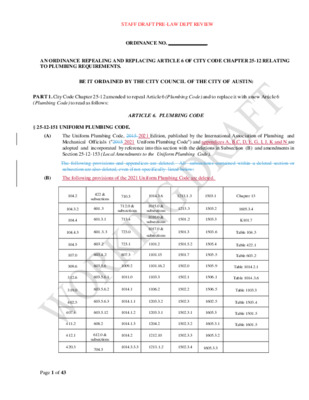
STAFF DRAFT PRE-LAW DEPT REVIEW ORDINANCE NO. _______________ AN ORDINANCE REPEALING AND REPLACING ARTICLE 6 OF CITY CODE CHAPTER 25-12 RELATING TO PLUMBING REQUIREMENTS. BE IT ORDAINED BY THE CITY COUNCIL OF THE CITY OF AUSTIN: PART 1. City Code Chapter 25-12 amended to repeal Article 6 (Plumbing Code) and to replace it with a new Article 6 (Plumbing Code) to read as follows: § 25-12-151 UNIFORM PLUMBING CODE. ARTICLE 6. PLUMBING CODE (A) The Uniform Plumbing Code, 2015 2021 Edition, published by the International Association of Plumbing and Mechanical Officials ("2015 2021 Uniform Plumbing Code") and appendices A, B,C, D, E, G, I, J, K and N are adopted and incorporated by reference into this section with the deletions in Subsection (B) and amendments in Section 25-12-153 (Local Amendments to the Uniform Plumbing Code). The following provisions and appendices are deleted. All subsections contained within a deleted section or subsection are also deleted, even if not specifically listed below: (B) The following provisions of the 2021 Uniform Plumbing Code are deleted. 104.2 422 & subsections 710.3 104.3.2 601.3 712.0 & subsections 104.4 601.3.1 713.4 1014.3.6 1213.1.3 1503.1 Chapter 13 1213.3 1503.2 1501.2 1503.3 1605.3.4 K101.7 104.4.3 601.3.3 723.0 1501.3 1503.6 Table 104.5 1015.0 & subsections 1016.0 & subsections 1017.0 & subsections 104.5 107.0 309.6 312.6 319.0 402.5 407.4 411.2 412.1 420.3 603.2 603.4.2 723.1 807.3 1101.2 1501.5.2 1505.4 1101.15 1501.7 1505.5 Table 422.1 Table 603.2 603.5.6 1009.2 1101.16.2 1502.0 1505.9 Table 1014.2.1 603.5.6.1 1011.0 1103.3 1502.1 1506.1 Table 1014.3.6 603.5.6.2 1014.1 1106.2 1502.2 1506.5 603.5.6.3 1014.1.1 1203.3.2 1502.3 1602.5 603.5.12 1014.1.2 1203.3.1 1502.3.1 1605.3 608.2 1014.1.3 1204.2 1502.3.2 1605.3.1 Table 1103.3 Table 1503.4 Table 1501.5 Table 1601.5 612.0 & subsections 704.3 1014.2 1212.10 1502.3.3 1605.3.2 1014.3.3.3 1213.1.2 1502.3.4 1605.3.3 Page 1 of 43 STAFF DRAFT PRE-LAW DEPT REVIEW 104.2 603.5.6 909.0 1101.2 1501.5.2 Table 104.5 104.3.2 603.5.7 1007.0 1101.15 1501.7 Table 422.1 104.4.3 603.5.12 1009.2 1101.16.2 1501.11 Table 603.2 Fire 104.5 608.2 1010.0 1103.3 1502.1 Table 1014.2.1 107.0 612.0 101 1.0 1106.2 1502.2.1 Table 1014.3.6 319.0 704.3 1012.0 1203.3.1 1502.6 Table 1103.3 407.4 710.2 1013.0 1203.3.2 1502.7 Table 1502.4 411.2 710.3 1014.1 1204.2 1503.5 Table 1601.5 412.1 711.0 1014.2 1212.10 1504.1 Appendix F 420.3 712.0 1014.3.3 1213.1.2 1504.5 Appendix H I 422.2 713.4 1014.3.6 1213.1.3 1505.6 601.3 723.0 1015.0 1213.3 1602.5 603.2 804.1 1016.0 Chapter 13 1602.11 603.4.2 807.3 1017.0 1501.2 K 101.7 (C) The city clerk shall file a copy of the 2015 2021 Uniform Plumbing Code with the official ordinances of the City. § 25-12-152 CITATIONS TO THE PLUMBING CODE. In the City Code, "Plumbing Code" means the 2015 2021 Uniform Plumbing Code adopted by Section 25-12-151 (Uniform Plumbing Code), as amended by Section 25-12- 153 (Local Amendments to the Uniform Plumbing Code). § 25-12-153 LOCAL AMENDMENTS TO THE UNIFORM PLUMBING CODE. The following provisions are local amendments to the 2015 2021 Uniform Plumbing Code. Each provision in this section is a substitute for the identically numbered provision deleted by Section 25-12-151(8) (Uniform Plumbing Code) or is an addition to the 2015 2021 Plumbing Code. 104.1.1 Persons authorized to obtain permits. A responsible master plumber licensed by the State of Texas and registered with the City may obtain a permit required by the Plumbing Code. Only a responsible master plumber with a master medical gas endorsement may obtain a plumbing permit related to medical gas installations. Only a responsible master plumber with a master water supply protection specialist endorsement may obtain a plumbing permit for an auxiliary water system that supplies plumbing fixtures. potable rain water system. Page 2 of 43 STAFF DRAFT PRE-LAW DEPT REVIEW Exception. An individual who is not licensed as a plumber may obtain a plumbing permit for plumbing work. That may, under state law, be completed by an unlicensed individual. 104.1.2 Homestead permit. An individual who is not licensed to perform plumbing work may perform plumbing work within a residence and on property owned by the individual. if the work does not include any auxiliary or alternative water system that has components interior to a building or serves plumbing fixtures, except for a gravity gray water system with a maximum discharge capacity of 250 gallons per day for a one-or-two family dwelling or townhome. . An individual must apply for a homestead permit in person, present a picture identification, and file an affidavit stating that the location at which the work is to be completed is the individual's homestead. An individual with a homestead permit may not allow or cause another individual to work under the homestead permit. If the work done under the homestead permit is performed by anyone other than the person who obtained the permit, the building official may suspend or revoke a homestead permit. A homestead permit may not be transferred to another person. If requested by the building official or his designee, a person with a homestead permit must provide proof of residence and ownership. 104.1.3 Licensing. A person who enters into a contract to install or repair a plumbing system subject to the Plumbing Code for which a permit is required must be licensed by the State of Texas. 104.1.3.1 Registration. A licensed plumber must register with the City before performing any work regulated by the Plumbing Code. 104.1.4 Landscape irrigation. A person licensed by the Texas Commission on Environmental Quality (TCEQ) to install irrigation systems must register with the City before performing any work required by the Plumbing Code. A person must pay a registration fee at the initial registration with the City or after a license is suspended or expired. A plumbing permit must be obtained before installing a landscape irrigation or yard sprinkler system. 104.1.5 Special inspections program for timed inspectionsCommercial plumbing change-out program. The building official may establish by rule an inspection program of commercial plumbing components identified in this section in buildings not covered under the International Residential Code or the Special Inspections Programs a change-out program authorizedincluded in other technical or building codes. The buildings must be located within Austin full purpose jurisdiction.the zoning jurisdiction of the City and, subject to agreement with a municipal utility district or a premises where the City provides water, reclaimed water, or wastewater service, may be located outside of the zoning jurisdiction. This program applies to replacing existing a water heater, backflow device or assembly, and to repairing or replacing a sewer line in occupied structures. 104.2 Exempt work. A permit is not required for the following activities: 1. work required to stop a leak in a drain, soil, waste, or vent pipe if it is not necessary to remove and replace a defective concealed trap, drain, pipe, solid, waste, or vent pipe with new device; 2. work required to clear a stoppage, including removing and reinstalling a water closet or to repair a leak in a pipe, valve, or fixture if the repair does not involve or require the valves, pipes, or drains be replaced or rearranged; 3. work required to repair or replace fixtures and to replace exposed traps, continuous waste piping, fixture supply valves, or faucets if the work does not involve other city departments or inspections from other trades. All work exempt from a permit must comply with the requirements of the Plumbing Code and all other laws or ordinances. 104.2 Exempt Work. A permit shall not be required for the following: 1. The stopping of leaks in drains, soil, waste, or vent pipe, provided, however, that a trap, drain pipe, soil, waste, or vent pipe become defective, and it becomes necessary to remove and replace the same with new material, the same shall be considered as new work and a permit shall be procured and inspection made as provided in this code. 2. The clearing of stoppages, including the removal and reinstallation of water closets, or the repairing of leaks in pipes, valves, or fixtures, provided such repairs do not involve or require the replacement or rearrangement of valves, pipes, or fixtures. Page 3 of 43 STAFF DRAFT PRE-LAW DEPT REVIEW 3. Work required to repair or replace fixtures and to replace exposed traps, continuous waste piping, fixture supply valves, or faucets if the work does not involve other city departments or inspections from other trades. 4. Other work as determined by the building official Exemption from the permit requirements of this code shall not be deemed to grant authorization for work to be done in violation of the provisions of the code or other laws or ordinances of this jurisdiction. For the purpose of this code section a shower, tub or combination tub and shower, new installation or replacement is not exempted from permitting. 104.3.4 Application. The person applying for a plumbing permit must be a responsible master plumber licensed by the State of Texas. The responsible master plumber must also be registered with the City. 104.4.3 Permit expiration and reactivation. A plumbing permit is subject to the requirements for permit expiration and reactivation, including an enhanced fee for expired permits, are set forth in Chapter 25-12, Article 13 (Administration of Technical Codes). 104.4.3 Time Limits. City Code Chapter 25-12, Article 13 (Administration of Technical Codes) establishes permit application time limits and requirements applicable to permit expiration and reactivation, including a review fee for expired permits. 104.5 Fees. The City will only issue permits and approve plans if the fees are paid. Fees are set by separate ordinance. 104.5 Fees. Fees applicable to this code are set by separate ordinance. Continuance of work inspection. A permit holder may schedule a continuance of work inspection if structural 104.5 or other conditions exist at the site that do not allow for an inspection to be performed at an interval of less than 180 days. If the inspector determines that work has been performed, the expiration date for the permit will automatically extend another 180 days. If the inspector determines that work has not been started, or continued, the permit will expire, and no work can continue until the permit holder applies for and receives a new permit. Offense. A person who violates Section I04.1 (Permits required) commits an offense, which is a class C 104.6 misdemeanor. Each day a person violates this section or remains in violation of Section I 04.1 (Permits required) is a separate occurrence. A culpable mental state is not required for the commission of an offense under this section, and need not be proved. 104.6 Offense and Penalty. A person who violates a provision of this code commits a separate offense for each day the violation continues and is subject to the penalty prescribed by Section 25-1-462 (Criminal Enforcement). 107.0 Mechanical and Plumbing Board. The Mechanical and Plumbing Board is governed by the requirements in Chapter 2-1 (City Boards) of the City Code. 108.0 The Building Criteria Manual. Additional information on procedures and rules related to administering the plumbing Code is available in the Building Criteria Manual. 108.0 Private sewage systems. On-site sewage systems and private sewage disposal systems must comply with Chapter 15-5 (Private Sewage Facilities) of the City Code and any regulations or requirements promulgated by the Austin Water Utility or the Texas Commission on Environmental Quality's (TCEQ) authorized agent. 202.1.1 Definitions. 203.1 ALTERNATE WATER SOURCE means water from a supply that is not the City's potable water supply and is also referred to as "Auxiliary Water". This definition supersedes the definition used in the 2015 Plumbing Code. 214.1 LAUNDRY TO LANDSCAPE SYSTEM means an auxiliary alternate water system that utilizes the collection of gray water discharged from clothes washing machines located at private one-and two-family dwellings for landscape irrigation. This definition supplements the definitions in Section 214 of the 2015 the Plumbing Code. PLUMBING SYSTEM means all potable water, building supply, and distribution pipes; all plumbing fixtures and traps; all drainage and vent pipes; and all building drains and building sewers, including their respective joints and connections, devices, receptors, and appurtenances within the property lines of the premises and includes potable water piping, alternate or auxiliary water source systems, irrigation systems, portable water treating or using equipment, medical gas Page 4 of 43 STAFF DRAFT PRE-LAW DEPT REVIEW and medical vacuum systems, liquid and fuel gas piping, and water heaters and vents for same. This definition supersedes the definition in the included in Section 218 of the 2015 Plumbing Code. 218.2 PROPERTY OWNER CUT-OFF means a full open or full port valve located on the discharge side of a water service from the public water supply. This definition supplements the definitions in Section 218 of the Plumbing Code. 218.3 POTABLE RAINWATER SYSTEM means a plumbing system that utilizes the principle of collecting, storing, using, and treating rainwater from a rooftop or other man-made, above-ground collection surface for the delivery of water that is satisfactory for drinking, culinary, or domestic purposes. This definition supplements the definitions in Section 218 of the 2015 Plumbing Code. 222.1 TRAP, DEEP SEAL P-TRAP means a fixture trap having a water seal of at least four inches but is not more than twice the diameter of the trap arm, and does not exceed 12 inches. This definition supplements the definitions in the Plumbing Code, a trap must be set true with respect to its water seal and where necessary be protected from freezing. 304.2 Sewage system connection required. If any part of a lot or tract that contains a house or building is located within 100 feet in horizontal distance (measured based on the closest practicable access route) of a public sewage disposal system, the drainage system of the house or building must be separately and independently connected to the public sewage disposal system. The drainage system is not required to be connected if: 1. 2. 3. the property owner received a denial of service in writing from the owner or governing body of the public sewage disposal system; the property owner received a written determination from Austin Water Utility that it is not feasible for the building to be connected to the public sewage disposal system; the property is served by an existing private sewage facility and Austin Water Utility determined the private sewage facility may continue to be used based on factors such as the type of building served; the age, condition, and capacity of the private sewage facility; and the availability of records related to the system, changes to the system, or the generating unit; or 4. A composting toilet serves the property and Austin Water Utility approved the disposal of liquid wastes in a private on-site sewage facility. 309.6 Private Hydrant Lines. Water lines from a private water main to a private fire hydrant with more than 100 gallons capacity, shall have backflow prevention protection as required by Chapter 15-1 (Cross-Connection Regulations). 312.6.1 Freeze protection. Plumbing must be installed with freeze protection. Acceptable methods to provide freeze protection include: 1. if the exterior wall member is at least six inches in nominal width, the piping may be placed on the conditioned side of the wall insulation and no additional pipe insulation is required; 2. if the exterior wall member is less than six inches nominal width, the piping shall be insulated with material with an R-value of at least four and the piping and pipe installation must be placed on the conditioned side of the wall; or 3. if the exterior wall member is uninsulated or the crawl space is unconditioned, an installed water pipe must be protected by pipe insulation with a minimum R-value of four; 4. if a water pipe is installed in an unconditioned attic above the building insulation, the water pipe must be protected by pipe insulation having an R-value of at least four. 312.6 Freeze Protection. Water lines installed outside of the building thermal envelope will require a minimum of 5/8 inch thick insulation with a minimum of R4 value. Page 5 of 43 STAFF DRAFT PRE-LAW DEPT REVIEW 319.0 Medical gas and vacuum systems. Any medical gas and vacuum system used in conjunction with human health care purposes must be installed consistent with the requirements in the most current edition at the effective date of this article of the National Fire Protection Association (NFPA) 99 entitled "Health Care Facilities Code" and the latest edition of the ANSI/ASSA Series 6000 titled "Professional Qualification Standards for Medical Gas System Installers, Inspectors, Verifiers, Maintenance Personnel and Instructors" to the extent the requirements conflict with the Texas State Board of Plumbing Examiners Plumbing License Law requirements. A medical gas system for non-human use must be installed consistent with Section 1305.0 in its entirety. 321.0 REQUIREMENTS FOR FLOOD PLAIN AREAS. 321.1 Definitions. 1. REGULATORY FLOOD DATUM (RFD) means an established plane of reference from which elevations and depth of flooding may be determined for a specific location of the flood plain. It is the water level of the design flood plus a freeboard factor of one foot. Design flood plus freeboard equals regulatory flood datum. 2. W-1 SPACE means a space that must remain completely dry during flooding to the RFD, with walls that are impermeable to water and water vapor consistent with the Building Code. 3. W-2 SPACE means a space that remains essentially dry during flooding to the RFD, with walls that are impermeable to water but may pass some water vapor or seep slightly consistent with the Building Code. 321.2 In this section, plumbing system includes sanitary and storm drainage, sanitary facilities, water supply, and storm water disposal systems. 321.3 A sanitary sewer or storm drainage system with an opening below the RFD must be provided with automatic backwater valves or other automatic backflow devices installed in each discharge line passing through an exterior wall. In a W-1 space, a manually operated shut-off valve that can be operated from a location above the RFD must be installed on the lines to serve as supplementary safety provisions for preventing backflow if the automatic backflow device fails. 321.4 If the dryness of a space depends on a sump pump system, all interior storm water drainage or seepage, appliance drainage, and under-slab drain tile systems must be directly connected to a sump pump and discharged at an elevation of five feet above the RFD. 321.5 A septic tank or disposal bed is not allowed in a 25-year flood hazard area. In other flood hazard areas, the use of a septic tank or disposal bed must be approved by Austin Water Utility. 321.6 (1) A potable water supply system that is located in the flood hazard area must be designed and installed in a manner that prevents contamination from floodwaters up to the RFD. 321.7 (2) An approved backflow preventer or device must be installed on main water service lines to a building entry location to protect the system from backflow or back siphonage of waters or other contaminants in the event of a line break. A device must be installed at an accessible location and must be maintained consistent with the Plumbing Code. 321.8 Establishment of flood hazard areas. The City establishes a flood hazard area that includes the following: 1. Areas of special flood hazard areas identified by the Federal Emergency Management Agency in the current scientific and engineering report entitled "The Flood Insurance Study (FIS) for Williamson County, Texas and Incorporated Areas" dated December 20, 2019, with accompanying Flood Insurance Rate Maps (FIRM) dated December 20, 2019, the current scientific and engineering report entitled "The Flood Insurance Study for Travis County, Texas and Incorporated Areas" dated January 6, 2016, with accompanying Flood Insurance Rate Maps dated January 6, 2016, and any revisions are adopted by reference and declared to be part of this section. Page 6 of 43 STAFF DRAFT PRE-LAW DEPT REVIEW 2. The 100-year and 25-year floodplains as defined in the Austin City Code are adopted by reference and declared to be part of this section. 322.0 Elevator sump pumps. If a pump and associated piping and materials required for elevators is installed under the rules of the Texas Administrative Code, Title 16, Part 4, Chapter 74, the pump and associated piping and materials must also comply with Sections 322.1 through 322.4. 322.1 Acceptable discharge location. In a new elevator shaft, an elevator sump pump must discharge to the storm system outside of the building, detention pond, or other location approved for each project by the authority having jurisdiction. A hydraulic elevator must be equipped with a hydraulic oil alarm and a secondary containment must be installed and approved for each project by the authority having jurisdiction. See City Code Section 15-10-12 (General Prohibition against Discharge) and Section 6-5-51(Discharge Restrictions). 322.2 Discharge piping. Piping must be at least one and a half inch (1½ inch) NPS. Piping must be independent and cannot connect to the storm or sub-soil piping within the building. Discharge piping must comply with Section 710.4 (Discharge line) of the Plumbing Code. If an elevator sump pump is located below the 100-year floodplain its piping must rise above the 100-year floodplain elevation before connecting to a gravity drainage system. Piping must be labeled as required in the Plumbing Code. 322.3 Materials. Piping materials for an elevator sump pump must be galvanized steel, galvanized wrought iron, copper, or other material approved by the authority having jurisdiction. Piping that is located within a shaft must be made of non- combustible materials. A transition to another approved material must be made outside of the elevator shaft using an approved transition fitting as required in Chapter 7 of the Plumbing Code. 322.4 Sample port. A sample port must be installed outside of the building on private property or another location approved by the authority having jurisdiction. Open grate catch basins, single riser two way cleanouts, or other approved fittings or receptors with the ability to visually see the flow line and retrieve samples are acceptable sample ports. 402.5 Settings. See section 2903.1.1 Water closets, urinals, lavatories and bidets in the 2021 International Building Code. 407.4 Transient Public lavatories. A lavatory that is intended to serves the transient public, like those in Group A, B, and M type occupancies as defined in the Building Code, must be equipped with self-closing or metering faucets. 408.5.1 Accessible shower stalls. In a Group I (Institutional) occupancy, as defined by the Building Code, a room that contains an accessible shower with a threshold or curb that is less than ½ inch in height or a roll-in accessible shower must be equipped with a Plumbing Code-approved emergency floor drain that is installed outside of the shower stall. 411.2 Water closets. The average water consumption of a water closet that is flush tank, flush-o-meter tank, or flush-o-meter valve operated may not exceed 1.28 gallons of water per flush. 412.1 Urinals. Urinals shall comply with ASME A112.19.2/CSA B45.1, ASME A112.19.19, or CSA B45.5/IAPMO Z124. Urinals shall have an average water consumption not to exceed one half gallon of water per flush. 412.1.1 Non-water urinals. A urinal without water must have a barrier liquid sealant to maintain a trap seal; must allow the uninhibited flow of waste through the urinal to the sanitary drainage system; and must be cleaned and maintained consistent with the manufacturer's instructions after installation. When a urinal without water is installed, at least one water supplied fixture (WSFU) must be installed upstream on the same drain line to facilitate drain line flow and rinsing; and must have a water distribution line rough-in to the urinal location to allow for the installation of an approved backflow prevention device in the event of a retrofit. If the authority having jurisdiction determines that a urinal without water is not maintained consistent with the manufacturer's instructions and that the urinal is a health hazard or detrimental to public health and safety, it must be retrofitted with a flushometer type urinal that complies with Section 412.1. If public health is compromised, the Building Official may to establish a timeline to retrofit the urinal. 412.3 Substitution for water closets. In a bathroom or toilet room of an assembly or educational occupancy, as defined by the Building Code, up to 67 percent of the required water closets may be urinals. In a bathroom or toilet room of all other occupancies, up to 50 percent of the required water closets may be urinals. 420.3 Pre-rinse spray valve. The maximum flow rate for a commercial food service pre- rinse spray valve is 1.28 gallons per minute (gpm) at 60 pounds force per square inch (psi) consistent with ASME A 112.18.1/CSA B125.1. A commercial food service valve must be equipped with an integral automatic shutoff. Page 7 of 43 STAFF DRAFT PRE-LAW DEPT REVIEW 422.0 Minimum Number of Required Fixtures. Minimum number of required fixtures will be determined as per 2021 International Building Code chapter 29 Plumbing Systems. Each building must be provided with sanitary facilities, including facilities designed for a person with a disability as determined by the Development Services Department. 422.1 Toilet Facilities for Workers. Toilet facilities shall be provided and maintained in a sanitary condition for the use of workers during construction. Table 422.1 Minimum Plumbing Facilities. Each building must be provided with sanitary facilities, including facilities designed for a person with a disability as determined by the Development Services Department. This table applies to new buildings, additions to buildings, and changes of occupancy, use, or type in an existing building that results in an increased occupant load. N O CLASSIFICATI ON OCCUPAN CY DESCRIPTI ON WATER CLOSETS (URINALS SEE SECTION 412.3) LAVATORIES OTHER BATH TUBS/ SHOWE RS DRINKIN G FOUNTAI NS (SEE SECTION 415) MALE MALE FEMAL E FEMAL E 1 per 65 1 Assembly A-1 1 per 125 1 per 200 1 per 200 —- 1 per 500 1 service sink A-2 1 per 40 1 per 40 1 per 75 1 per 75 —- 1 per 500 1 service sink 1 per 75 1 per 75 —- 1 per 500 1 per 200 1 per 200 1 service sink A-3 1 per 125 1 per 65 1 per 200 1 per 200 — 1 per 500 1 service sink 1 per 500 1 per 500 1 per 750 1 per 750 — 1 per 1,000 1 service sink 1 per 150 1 per 75 1 per 200 1 per 200 — 1 per 1,000 1 service sink Page 8 of 43 Theater and buildings for the performing arts and motion pictures Nightclubs, bars, taverns, dance halls, and buildings for similar purposes Banquet halls, food courts, and restaurants Auditoriums without permanent seating, art galleries, exhibition halls, museums, lecture halls, libraries, arcades and gymnasiums Passenger terminals and transportation facilities Places of worship and other religious services STAFF DRAFT PRE-LAW DEPT REVIEW 1 per 200 1 per 150 — 1 per 1,000 1 service sink 1 per 200 1 per 150 — 1 per 1,000 1 service sink 1 per 75 for the first 1,500 and 1 per 120 for the remaind er exceedi ng 1,500 1 per 75 for the first 1,500 and 1 per 120 for the remaind er exceedi ng 1,500 1 per 25 for the first 50 and 1 per 50 for the remaind er exceedi ng 50 1 per 40 for the first 1,520 and 1 per 60 for the remaind er exceedin g 1,520 1 per 40 for the first 1,520 and 1 per 60 for the remaind er exceedin g 1,520 1 per 25 for the first 50 and 1 per 50 for the remaind er exceedin g 50 1 per 40 for the first 80 and 1 per 80 for the remaind er exceedi ng 80 1 per 40 for the first 80 ad 1 per 80 for the remaind er exceedin g 80 2 Business — 1 per 100 1 service sink (e) 3 Educational E 1 per 50 1 per 50 1 per 50 1 per 50 — 1 per 100 4 Factory and Industrial F-1 F-2 1 per 100 1 per 100 1 per 100 1 per 100 1 per 400 See Section 416.0 5 Institutional I-1 1 per 10 1 per 10 1 per 10 1 per 10 1 per 8 1 per 100 I-2 1 per room (c) 1 per room (c) 1 per 15 1 per 100 1 service sink 1 service sink 1 service sink 1 service sink Page 9 of 43 A-4 A-5 Coliseums, arenas, skating rinks, pools and tennis courts for indoor sporting events and activities Stadiums, amusement parks, bleachers, and grandstands for outdoor sporting events and activities Buildings for the transactions of business, professional services, office buildings, banks, services involving merchandise and light industrial and similar uses Facilities for education Structures in which occupants are engaged in fabricating, assembly, or processing of products or materials Residential care Hospitals, ambulatory nursing home care recipient (b) STAFF DRAFT PRE-LAW DEPT REVIEW 1 per 25 1 per 25 1 per 35 1 per 35 — 1 per 100 — 1 per 75 1 per 75 — 1 per 100 — 1 per 100 1 per 100 I-3 Prisons 1 per cell 1 per 15 1 per 100 1 per 15 1 per 15 1 per 15 1 per 15 1 per 15 1 per 100 Employees 1 per 25 1 per 25 1 per 35 1 per 35 —- 1 per 100 — I-4 1 per 15 1 per 15 1 per 15 1 per 15 1 1 per 100 6 Mercantile M 1 per 500 1 per 500 1 per 750 1 per 750 — 1 per 1,000 7 Residential R-1 1 per sleeping unit 1 per sleeping unit — R-2 1 per 10 1 per 10 1 per 10 1 per 10 1 per 8 1 per 100 1 per dwelling unit 1 per dwelling unit — 1 per sleeping unit 1 per dwelling unit Employees, other than residential care (b) Visitors, other than residential care Reformatories, detention centers, and correctional centers Adult day care and child day care Retail stores, service stations, shops, salesrooms, markets, and shopping centers Hotels, motels, boarding homes (transient) Dormitory Fraternity Sorority Boarding homes (not transient) Apartment house 1 service sink 1 service sink 1 service sink 1 service sink 1 service sink 1 service sink 1 kitchen sink per dwelling unit; 1 automati c clothes washer connecti on per 20 dwelling units Page 10 of 43 STAFF DRAFT PRE-LAW DEPT REVIEW R-3 1 per dwelling unit 1 per dwelling unit — 1 per dwelling unit 1 per 10 1 per 10 1 per 10 1 per 10 1 per 8 1 per 100 R-4 1 per 10 1 per 10 1 per 10 1 per 10 1 per 8 1 per 100 1 kitchen sink per dwelling unit; 1 automati c clothes washer connecti on per dwelling unit 1 service sink 1 service sink One- and two- family dwellings and lodging houses with five or fewer guest rooms Congregate living facilities with 16 or fewer persons Congregate living facilities with more than 16 persons Structures for the storage of goods, warehouses storehouses and freight depots, low and moderate hazard 8 Storage S-1 and S-2 1 per 100 1 per 100 1 per 100 1 per 100 1 per 1,000 1 service sink See Section 416.0 (a) The fixtures shown are based on fixture being the minimum required for the number of persons indicated or any fraction of the number of persons indicated. The number of occupants is determined by the International Building Code. (b) Toilet facilities for employees must be separate from facilities for inmates and care recipients. (c) A single-occupant toilet room with one water closet and one lavatory serving not more than two adjacent patient sleeping units is allowed, provided that each patient sleeping unit has direct access to the toilet room and a provision for privacy for the toilet room user is provided. (d) The occupant load for seasonal outdoor seating and entertainment areas must be included when determining the minimum number of facilities required. (e) For business and mercantile occupancies with an occupant load of 30 or fewer, a service sink is not required. 422.2 Separate facilities. Where plumbing fixtures are required, separate facilities must be provided for each sex. Exceptions. Separate facilities are not required: 1. for dwelling units or sleeping units; 2. in structures or tenant spaces with a total occupant load, inclusive of employees and customers, of 15 or less; 3. in mercantile occupancies when the maximum occupant load is 100 or less; and 4. in a business occupancies when the maximum occupant load is 50 or less. Page 11 of 43 STAFF DRAFT PRE-LAW DEPT REVIEW 422.2.1 Family or assisted-use toilet facilities serving as separate facilities. If a building or tenant space requires a separate toilet facility for each sex but is only required to have one water closet, two family or assisted use toilet facilities may be allowed to serve as the required separate facilities. A family or assisted use facility may not be identified for exclusive use by either sex. 422.4 Required public toilet facilities. A structure or tenant space intended to be used by the public must have public toilet facilities for customers, patrons, and visitors to use. The number of plumbing fixtures within a required toilet facility must comply with Section 422.0 for all users. All occupancies must provide toilet facilities for employees and may be separate or combined with public toilet facilities. Exception. A public toilet facility is not required in 1. an open or enclosed parking garage without parking attendants; or 2. a structure or tenant space intended for quick transactions, including takeout, pick up and drop off, with a 300 square feet or less public access area. 422.4.1 Access. The route to a public toilet facility required in Section 403.3 may not pass through kitchens, storage or closets and must be accessible as required by the International Building Code. The public must have access to a required public toilet facility when the building is occupied and access must be from within the building or the exterior of the building. 422.4.2 Toilet room location. A toilet room may not open directly into a room used to prepare food that will be served to the public. 422.4.3 Location. In a shopping mall or center, the required toilet facilities for employees and customers may be provided in a centrally located toilet facility that is accessible to several stores and the travel distance from the entry of the store and the toilet facility must be 300 feet or less. In other occupancies, the travel distance required toilet facilities for employees and customers must be 500 feet or less. Access to toilet facilities. In a multi-story building, the route for toilet facilities cannot exceed one vertical story. 422.4.4 The route for customers cannot pass through areas designated for employee use only such as kitchens, food preparation areas, storage rooms, closets, or similar spaces. A toilet facility that may be accessed only from a private office may not be counted to determine compliance with this section. 501.2 Service water heating systems. A water heater that is installed after the effective date of the Plumbing Code and served by Austin Energy must comply with the Energy Code. Any replacement electrical equipment must comply with the Energy Cod 508.4.5 One and two family dwellings and townhouse type occupancies. A storage type water heater that exceeds a capacity of 17 gallons may not be installed in an attic or above a ceiling in a residential occupancy unless the water heater is accessible through a vertical door opening located in an occupied space on the same floor level. An attic or under-floor space in which an appliance is installed must be accessible through an opening and passageway that is at least as large as the largest component of the appliance but not less than 22 inches by 30 inches (559 mm by 762 mm). 504.7 Appliances Elevated Above an Occupied Space in Occupancy Covered under the International Building Code. Storage type water heaters exceeding a capacity of 17 gallons shall not be installed 8 feet above the finish floor, unless permanent access is provided that support a 300 pound concentrated load that complies with the requirements of the building code or permanent lifting equipment designed by a registered design professional is installed or lifting equipment access is provided from entry point to location of appliance. 504.7.1 One and two family dwellings and townhouse type occupancy. A storage type water heater that exceeds a capacity of 17 gallons may not be installed in an attic or above a ceiling in a residential occupancy unless the water heater is accessible through a vertical door opening located in an occupied space on the same floor level. 508.2 Roof Drainage and Rails. Equipment shall be installed on a well-drained surface of the roof. Guards must be provided where an appliance, equipment, fan, solar system, or other components require service and are located within 10 feet of a roof edge or open side of a walking surface and the edge or walking surface is located 30 inches above the grade below. Rigid fixed rails or guards at least 42 inches in height must be provided on the exposed side. The Page 12 of 43 STAFF DRAFT PRE-LAW DEPT REVIEW guard must be constructed to prevent a 21-inch-diameter sphere from passing through and must extend at least 30 inches beyond each end of the appliance, equipment, fan, or component. If a parapet or other building structure is used in lieu of a guard, it must be at least 42 inches in height. Exception: Guards shall not be required where a permanent fall arrest anchorage connector system in accordance with ASSE Z359.1 is installed. 601.1.1 Water system connection required. If any part of a lot or tract that contains a house or building is located within 100 feet in horizontal distance (measured based on the closest practicable access route) of a state-licensed public potable water system, the water system of the house or building must be separately and independently connected to the public water system. The water system is not required to be connected if: 1. 2. 3. the property owner received a denial of service in writing from the owner or governing body of the public water system; the property owner received a written determination from Austin Water Utility that it is not feasible for the building to be connected to a potable water system; or the property is served by an existing private potable water system and Austin Water Utility determined the private potable water system may continue to be used based on factors such as the type of building served; the age, condition, and capacity of the private potable water system; the quality of the water; and the availability of records related to the system, changes to the system, or the system demand. 601.1.2 If a state-licensed public potable water system is not available within the full purpose jurisdiction of the City, then an alternative system for potable water must be installed consistent with the Plumbing Code. 601.3 Identification of a potable and non-potable water system. If potable water and non-potable water systems are installed on the same site, then each system must be labeled and identified consistent with the requirements in Section 601.3.1 through Section 601.3.4. Exception. Potable water piping inside a building does not require labeling if the non-potable water system does not enter the building. 601.3.1 Potable water. The system must be identified using a green background and white lettering. Color and information. A water system must be identified with a colored pipe or sleeve and coated with paints, 601.3.2 wraps, and materials that are compatible with the piping. Except as required in Section 601.3.3, a non-potable water system must have a yellow background with black uppercase lettering and labeled “CAUTION: NONPOTABLE WATER, DO NOT DRINK". A non-potable water system must be identified in a manner that designates the liquid being conveyed and shows the direction of normal flow. The size of letters and length of the color field must comply with Table 601.3.3. For piping above grade, the background color and the required information must be indicated every 20 feet (6096 mm) but not less than once per room, on both sides of the wall or partition penetrated by the piping, and at least once in every story height traversed by risers. For piping below grade, the background color and the required information must be indicated every five feet, except that all reclaimed piping shall be purple pipe or painted purple (Pantone color No. 512, 522C or equivalent). Exception. The pipe and components of an existing irrigation system that is converted to an auxiliary alternate water source located below grade may remain unmarked until disturbed. Any repair, additions, or alterations must be identified consistent with Section 601.3.2. All pipe and components located above grade or accessible within a subsurface vault must be identified consistent with TCEQ 344.65(3). 601.3.3 Alternate (auxiliary) water source. An alternate water source system must have a purple (Pantone color no. 512, 522C, or equivalent) background with uppercase lettering and shall be field or factor marked as follows: 1. A gray water system must be marked with "CAUTION: NON POTABLE GRAY WATER, DO NOT DRINK" in uppercase yellow (Pantone No. 108 or equivalent) black letters; 2. All reclaimed (recycled) water system piping shall be purple pipe or painted purple marked with "CAUTION: NONPOTABLE RECLAIMED (RECYCLED) WATER, DO NOT DRINK" in uppercase black letters; 3. An on-site treated water system shall be marked with "CAUTION: ON-SITE TREATED NONPOTABLE WATER, DO NOT DRINK" in uppercase black letters; Page 13 of 43 STAFF DRAFT PRE-LAW DEPT REVIEW 4. A rainwater catchment system shall be marked with "CAUTION: NONPOTABLE RAINWATER WATER, DO NOT DRINK" in uppercase black letters; and 5. Other on-site non-potable water systems must be marked with "CAUTION: NONPOTABLE WATER, DO NOT DRINK" in uppercase yellow (Pantone No. I08 or equivalent) letters. 601.3.4 Fixtures. When vacuum breakers or backflow preventers are installed with a fixture listed in Table 1701.1, the discharge side is not required to be identified. 601.3.5 Outlets. An outlet on a non-potable water line used for special purposes must be marked with "CAUTION: NONPOTABLE WATER, DO NOT DRINK" in uppercase black letters. Table 603.2 Backflow Prevention Devices, Assemblies, and Methods DEGREE OF HAZARD Degree of Hazard Back- Siphon age Back- Pressur e Back- Siphon age Back- Pressur e Device, Assembly, or Method 1 Applicable standards Pollution (Low Hazard) Contamination (High Hazard) Installation 2,3 Air gap Air gap fittings for use with plumbing fixtures, appliances, and appurtenances Atmospheric vacuum breaker (consists of a body, checking member and atmospheric port) Antisiphon fill valve (ballcocks) for gravity water closet flush tanks and urinal tanks Vacuum breaker wall hydrants, hose bib’s, frost resistant, automatic draining type ASME A112.1.2 ASME A112.1.3 ASSE 1001 or CSA B64.1.1 ASSE 1002/ASME A112.1002/ CSA B125.12 ASSE 1019 or CSA B64.2.1.1 Hose connection vacuum breakers ASSE 1011 Hose connection backflow preventers ASSE 1052 X X X X X X X _ _ _ _ _ _ _ X X X X X X X _ _ _ _ _ _ _ See Table 603.3.1 in this chapter. Air gap fitting is a device with an internal air gap, and typical installation includes plumbing fixtures, appliances, and appurtenances. The critical level shall not be installed below the flood level rim. Upright position. No valve downstream. Minimum of six 6 inches or listed distance above all downstream piping and flood level rim of receptor. 4, 5 Installation of gravity water closet flush tank and urinal tanks with the fill valve installed with the critical level not less than 1 inch above the opening of the overflow pipe. 4, 5 Installation includes wall hydrants and hose bibbs. Such devices are not for use under continuous pressure conditions (means of shutoff downstream of device is prohibited). 4,5 Such devices are not for use under continuous pressure conditions. No valve downstream. 4,6 Such devices are not for use under continuous pressure conditions.4,6 Page 14 of 43 STAFF DRAFT PRE-LAW DEPT REVIEW Backflow preventer for beverage dispensers (2 independent check valves with a vent to the atmosphere ASSE 1022 X Dual check backflow preventer wall hydrants, freeze resistant ASSE 10571053 Freeze resistant sanitary yard hydrants ASSE 10121057 X X - _ _ - X X ASSE 1012 X X _ ASSE 1081 X X _ - _ _ _ _ Installation does not include carbonated beverage dispensers and installation must comply with manufacturer’s installation requirements Such devices are not for use under continuous pressure conditions.4 Such devices are not for use under continuous pressure conditions.4 Installation of potable water connections to potable water boilers. No high-hazard chemicals shall be introduced into the system using such devices. Designed to operate under continuous pressure conditions. May discharge water. Installation of potable water connections to potable water boilers. No high-hazard chemicals shall be introduced into the system using such devices. Designed to operate under continuous pressure conditions. May discharge water. USC FCCCHR7 –– X –– Upright position. Minimum of 12 inches or listed distance above all downstream piping and flood- level rim of receptor.5 X X Double Check Valve Backflow Prevention Assembly (two independent check valves and means of field testing) USC FCCCHR7 X –– –– Horizontal unless otherwise listed. Access and clearance shall be in accordance with the manufacturer’s instructions, and not less than a 12 inch clearance at the bottom for maintenance. May need platform/ladder for test and repair. Does not discharge water. Horizontal unless otherwise listed. Access and clearance shall be in accordance with the manufacturer’s instructions, and not less than a 12 inch clearance at the bottom for maintenance. May need platform/ladder for test and repair. Does not discharge water. Installation includes a fire protection system and is designed to operate under continuous pressure conditions. Upright position. May have valves downstream. Minimum of 12 inches above all downstream piping and flood-level rim of the receptor. May discharge water. USC FCCCHR7 X X –– –– USC FCCCHR7 X –– X –– Backflow preventer with intermediate atmospheric vent Backflow preventer with intermediate atmospheric vent and pressure reducing valve Spill-Resistant Pressure Vacuum Breaker (single check valve with air inlet vent and means of field testing) Double Check Detector Fire Protection Backflow Prevention Assembly (two independent check valves with a parallel detector assembly consisting of a water meter and a double check valve backflow prevention assembly and means for field testing) Pressure Vacuum Breaker Backflow Prevention Assembly (loaded air inlet valve, internally loaded check valve and means for field testing) Page 15 of 43 STAFF DRAFT PRE-LAW DEPT REVIEW USC FCCCHR7 X X X USC FCCCHR7 X X X X X Horizontal unless otherwise listed. Access and clearance shall be in accordance with the manufacturer’s instructions, and not less than a 12 inch clearance at the bottom for maintenance. May need platform/ladder for test and repair. May discharge water. Horizontal unless otherwise listed. Access and clearance shall be in accordance with the manufacturer’s instructions, and not less than a 12 inch clearance at the bottom for maintenance. May need platform/ladder for test and repair. May discharge water. Installation includes a fire protection system and is designed to operate under continuous pressure conditions. ASSE 1035 –– –– X X Installation includes laboratory faucets. Such devices are not for use under continuous pressure conditions. No valve downstream.4 Reduced Pressure Principle Backflow Prevention Assembly (two independently acting loaded check valves, a differential pressure relief valve and means for field testing) Reduced Pressure Detector Fire Protection Backflow Prevention Assembly (two independently acting loaded check valves, a differential pressure relief valve, with a parallel detector assembly consisting of a water meter and a reduced-pressure principle backflow prevention assembly, and means for field testing) Laboratory faucet backflow preventer For SI units: 1 inch = 25.4 mm Notes: See the description of devices and assemblies in this chapter. Installation in pit or vault requires previous approval by the Authority Having Jurisdiction. 1. 2. 3. Refer to the general and specific requirement for installation. 4. Not to be subjected to operating pressure for more than 12 hours in a 24 hour period. 5. 6. 7. Current list of approved backflow prevention assemblies, University of Southern California Foundation for Cross-Connection Control and Hydraulic Research. For deck-mounted and equipment-mounted vacuum breaker, see Section 603.5.13. Shall be installed in accordance with Section 603.5.7. 603.2 Approval of devices or assemblies. A device or an assembly may be installed for the prevention of backflow if it is approved by the authority having jurisdiction before it is installed. A device or an assembly must be tested consistent with recognized standards or another standard, if acceptable to the authority having jurisdiction. A backflow prevention device or assembly must comply with Table 603.2 and Chapter 15-1 (Cross- Connection Regulations) of the City Code, except for a specific application or provision included in Sections 603.5.1 through 603.5.20. A device or assembly installed in a potable water supply system for protection against backflow must be maintained in good working condition by the person or persons with control of the device or assembly. A device or an assembly must be tested at the time of installation, repair, or relocation and when required by the authority having jurisdiction. If the device or assembly is determined to be defective or inoperative, the device or assembly must be repaired or replaced. Before a device or assembly may be removed from use, relocated, or substituted with another device or assembly, the authority having jurisdiction must approve of the action. A backflow assembly tester, licensed by the State of Texas and registered with the City, must conduct testing consistent with the requirements in Chapter 15-1(Cross-Connection Regulations) of the City Code. 603.4.2 Testing. The owner or other responsible person for a premises must have the backflow prevention assembly tested by a backflow assembly tester, licensed by the State of Texas and registered by the City, at the time of installation, repair, or relocation and when otherwise required by the authority having jurisdiction. Periodic testing must be performed consistent with the requirements in Chapter 15-1 (Cross-Connection Regulations) of the City Code. 603.4.10 Hazard isolation. A separate backflow prevention assembly or device must be installed on a high hazard appurtenance or fixture in high hazard situations when water or product is intended for contact with humans either directly (consumption, bathing, medical uses, dental chairs, pharmaceuticals, etc.) or indirectly (sterilization, autoclaves, washing dishes or bottles, canning, etc.). Exception. Potable water supplied to carbonators must be protected with a listed reduced pressure principal backflow preventer that is approved by the authority having jurisdiction for that specific use. A single reduced pressure principal Page 16 of 43 STAFF DRAFT PRE-LAW DEPT REVIEW backflow prevention assembly device (RPZ) may be installed for multiple carbonators that are located in the same immediate physical area if all water piping from the backflow preventer to the carbonator is exposed. Piping downstream of backflow protection for carbonators cannot be affected by carbon dioxide gas. 603.4.10.1 Multiple high hazards. If no human contact is intended, then a single backflow prevention assembly or device may be installed for multiple high hazard appurtenances or fixtures. Each water line downstream of the backflow protection must be labeled consistent with requirements for non-potable water labeling. 603.4.10.2 Multiple low hazards. In low hazard situations that service multiple low hazards of the same type and are located in the same immediate physical area, a single backflow prevention assembly or device may be installed if all piping downstream of the backflow protection is exposed. 603.5.6 Protection from lawn sprinklers and irrigation systems. Potable water that is supplied to a system that lacks pumps or connections for pumping equipment and lacks chemical injection or the provisions for chemical injection must be protected from backflow using one of the following devices: 1. atmospheric vacuum breaker (AVB); 2. Pressure vacuum breaker backflow prevention assembly (PVB); 3. spill-resistant pressure breaker vacuum breaker (SVB); 4. reduced-pressure principle backflow prevention assembly (RP); 5. Double check valve assembly (DCVA). 603.5.6.1 Systems with pumps. When a sprinkler or irrigation system has pumps, connections for pumping equipment, auxiliary air tanks, or otherwise capable of creating backpressure and the backflow device is located upstream from the source of backpressure, the potable water supply must be protected using one of the following devices: 1. Reduced-pressure principle backflow prevention assembly (RP); or 2. Double check valve assembly (DCVA). 603.5.6.2 Systems with backflow devices. The backflow device installed downstream from a potable water supply pump or a potable water supply pump connection must be: 1. atmospheric vacuum breaker (AVB); 2. pressure vacuum breaker backflow prevention assembly (PVB); 3. spill-resistant pressure vacuum breaker (SVB); 4. reduced-pressure principle backflow prevention assembly (RP); or 5. Double check valve assembly (DCVA). 603.5.6.3 Systems with chemical injectors. The potable water supply shall be protected by a RP in a system with a chemical injector or provisions for chemical i n j e c t io n. 603.5.7 Outlets with hose attachments. A potable water outlet with a hose attachment, other than a water heater drain, boiler drain, or clothes washer connection, must be protected by a non-removable hose bib type backflow preventer, a non-removal hose bib type vacuum breaker, or by an atmospheric vacuum breaker installed at least 6 inches (152 mm) above the highest point of usage located on the discharge side of the last valve. In a climate that experiences freezing temperatures, a listed self- draining frost-proof hose bib with an integral backflow preventer or vacuum breaker must be used. A standard hose bib is allowed if protected by additional pipe insulation with an R-value of at least four up to the edge or wall flange of the hose bib 603.5.12 Beverage dispensers. The potable water supply to a beverage dispenser or coffee machine must be protected by an air gap or vented backflow preventer consistent with ASSE I022. The potable water supply to a beverage dispenser or coffee machine shall be protected by an air gap, DCVA, or vented backflow preventer consistent with ASSE 1022 installed and maintained per the manufacturer’s requirements. Page 17 of 43 STAFF DRAFT PRE-LAW DEPT REVIEW 603.5.12.1 Carbonated beverage dispenser. The potable water supply to a carbonated beverage dispenser must be protected by an air gap or a RP. The piping material installed downstream of the backflow preventer cannot be affected by carbon dioxide gas. 603.5.12.2 Beverage dispenser in healthcare facilities. The potable water supply to a beverage dispenser or coffee machine that is located within a healthcare facility and subject to NFPA 99 must be protected by a testable backflow prevention assembly as defined in Chapter 15-1 (Cross-Connection Regulations) of the City Code. 603.5.22 Site containment backflow prevention requirements. A site that utilizes an alternate water source (auxiliary water) must provide an air gap or a mechanical backflow protection device located immediately downstream of all potable City water meters and City service lines to private fire lines consistent with Table 603.5. Exception. A non-potable rainwater catchment or non-potable condensate collection system of 500 gallons or less does not require backflow prevention at the potable water meter. 603.5.23 Cooling tower reservoirs. A water supply inlet that terminates inside the envelope of a cooling tower must be protected with a reduced air pressure principle backflow prevention assembly. A water supply inlet that terminates outside the envelope of a cooling tower must be protected by an air gap or reduced air pressure principle backflow prevention assembly. Table 603.5 Backflow prevention required at potable water connection List of Auxiliary alternate Water Sources and Uses(1) Domestic water meter (2) Irrigation Water meter (2) City service to private fire mains (2), (3), (4), (5) Backflow protection required at point of interconnection with potable water RP RP RP RP Lake/River water Well water Condensate I Gravity - water Pumped RP Rain water Gravity - DC (5) Gray water Gravity - DC (5) Pumped RP Pumped RP DC (5) RP RP RP RP RP RP RP Reclaim water (6) Other water supply (7) Page 18 of 43 DC DC DC DC DC DC DC DC DC DC RP RP RP RP RP RP AG AG AG AG STAFF DRAFT PRE-LAW DEPT REVIEW Table Notes RP= reduced pressure zone backflow prevention assembly DC - double check backflow prevention assembly AG air gap (1) If multiple sources of auxiliary alternate water are used, all backflow protection must meet the most stringent requirements of the sources used. (2) A backflow prevention assembly installed at the potable service connection of a site served by an auxiliary alternate water source must have an annual operational test. (3) A new backflow prevention assembly installed in an existing fire system may result in the need to re- calculate fire system design specifications due to backflow preventer pressure losses. (4) A backflow prevention assembly installed in an un-metered fire system is required to be a detector assembly. (5) These backflow prevention assemblies are required regardless of the presence of auxiliary alternate water. (6) When a chemical addition system is used (e.g. fertigation) a DC will be required on the reclaimed water service connection. (7) Other water supply includes any and all other auxiliary alternate waters not listed in the table. 606.2.1 Property owner cut off (POCO). A customer or property owner is required to install, on the side where the water services enters the property, a customer or property owner cut-off valve and to maintain the valve. The valve may not be located inside of a City meter box or vault. A "POCO" valve installed on a meter extension must be ball valves, full port, with stainless steel handles, threaded and conform to MSS-SP-110. The threads must comply with ASME B1.20.1. 606.2.1 Full-way valve installation location. A full-way valve installed on the discharge side of the water meter is prohibited from being installed inside the City of Austin meter box or vault. Exception. A full-way valve on the discharge side of the water meter may be installed in the City of Austin meter box or vault due to space limitations with written consent from Austin Water. 608.2 Excessive water pressure. If local static water pressure exceeds 65 pounds per square inch, an approved pressure regulator preceded by an adequate strainer must be installed to reduce the static pressure to 65 pound per square inch or less. A pressure regulator that is equal to or exceeds one and one-half inches does not require a strainer. The regulator must control the pressure to all water outlets in the building unless otherwise approved by the authority having jurisdiction. The regulator and, if required, strainer must be accessible, located above ground or in a vault, and protected from freezing. The strainer must be readily accessible for cleaning without removing the regulator or the strainer body or disconnecting the supply piping. Pipe size determinations are based on 80 percent of the reduced pressure when using Table 6-6 (Fixture Unit Table for Determining Water Pipe and Meter Sizes). An approved expansion tank must be installed in the cold water distribution piping downstream of the regulator to prevent excessive pressure from developing because of thermal expansion and to maintain the pressure setting of the regulator. An expansion tank used in a potable water system intended to supply drinking water must comply with NSF 61. An expansion tank must be properly sized and installed consistent with the manufacturer's installation instructions and listing. A system designed by a registered design professional may use Approved pressure relief valves in lieu of expansion tanks provided the relief valve has a maximum pressure relief setting of 100 pounds per square inch (698 kPa) or less. Exception. A one-or two-family dwelling or a townhome that is required to install a multi-purpose fire protection system may have static water pressure up to 80 pounds per square inch. 609.11.3 Conflicts between codes. If the requirements of the Plumbing Code conflict with the requirements of the International Energy Conservation Code, the most restrictive requirement applies. 609.13 Private Fire Lines. A private fire line must be installed consistent with the latest version of the National Fire Protection Association (NFPA) 24 Standard for the Installation of Private Fire Service Mains and their Appurtenances, as adopted by the Austin Fire Department Fire Protection Criteria Manual. A private fire line must comply with the NFPA 25 Standard for the Inspection, Testing, and Maintenance of Water-Based Fire Protection Systems as required by the Austin Fire Department. Table 610.1 Water Meter Sizing for Residential Single Family Homes, Duplex, and Townhomes Maximum Water Fixture Units 1 Water meter size 2 Typical number of bathrooms Page 19 of 43 STAFF DRAFT PRE-LAW DEPT REVIEW 35 fixture units 40 fixture units 44 fixture units 52 fixture units 55.5 fixture units 70 fixture units 78 fixture units 84.5 fixture units 5/8" meter ¾" meter ¾" meter ¾" meter ¾" meter l" meter 1" meter 1" meter 3 bathrooms or less 3 ½ bathrooms 4 bathrooms 5 bathrooms 5 ½ bathrooms 6 bathrooms 7 bathrooms 8 bathrooms 1. Standard rounding conventions apply when determining Water Supply Fixture Units (WSFU). 2. To be approved for a meter size based on the WSFU, an applicant must provide calculations when the Water and Wastewater Service Plan and Verification consultation with Austin Water Utility occurs. The calculations must be based on static water pressure at the meter, distance to furthest fixture, elevation differential to highest fixture, and on the total WSFU count for the property. 610.1.1 Size of water meters for one- and two-family dwellings and townhomes. An Austin Water meter provided to one-or-two family dwellings or townhomes must be sized based on the requirements in Table 610.1. 612.0 Residential fire sprinkler systems. When a residential sprinkler system is required in a one-or-two family dwelling or townhome, the system must be installed consistent with the International Residential Code Section P2904 or NFPA 13D and must comply with the Fire Code. 612.1 Types of systems. This section applies to a stand-alone or multipurpose wet-pipe sprinkler system that does not use antifreeze. A multipurpose fire sprinkler system must provide potable water to both fire sprinklers and plumbing fixtures. A stand-alone sprinkler system must be separate and independent from the potable water system. A backflow prevention assembly must separate a stand-alone sprinkler system from the potable water supply. 613.0 Plumbing for multi-family sub-meters. A newly constructed multi-family housing unit or a residential unit in a mixed-use facility must have a single cold water stub out that supplies all fixtures within each dwelling unit that is supplied by the master meter. A City meter or privately-owned water meter must be installed for each newly constructed unit at the time of construction. Each stub out must have a shut off valve immediately ahead of the private meter location. The meter must have a clearance of at least four inches on each side. The private meter must be installed in a location that is accessible for reading, testing, replacement, and inspection. Exception. A development with a centralized hot water system is not required to comply with this section. 614.0 Cooling towers. A cooling tower must include a makeup and blowdown meter, conductivity controllers, overflow alarms, drift eliminators, and a minimum of 5 cycles of concentration when potable water is utilized. A cooling tower must comply with the Mechanical Code. 614.0 Landscape irrigation. Irrigation for landscape must comply with the requirements in Chapter 344, Title 30 of the Texas Administrative Code; Texas Commission on Environmental Quality; and Sections 614.1 through 614.2 of the Plumbing Code. Definitions. In Sections 615.1 through 615.3: HYDROZONING means the practice of grouping sprinkler heads into zones with similar vegetation, soil types, slopes, and sunlight availability. ISOLATION VALVE means the valve used to isolate all or part of the irrigation system for repairs, maintenance, winter, or emergency shut-down. 615.1 Requirements for new commercial and multi-family landscape irrigation installation. A new commercial or multi-family irrigation system must be designed and installed to include: Page 20 of 43 STAFF DRAFT PRE-LAW DEPT REVIEW 1. spray irrigation that is limited to areas that are more than six feet wide (medians, buffer strips, and parking lots islands should not be spray irrigated); 2. above-ground irrigation emission devices that are located at least six inches from impervious cover surfaces; 3. master valve for the system; 4. circuit remote control valves that have adjustable flow controls; 5. serviceable in-head check valves that are adjacent to paved areas where the elevation differences may cause low head drainage; 6. a rain shut-off device that shuts off the irrigation system automatically at or before ½ inch rainfall; 7. zone valves and circuits that are separated based on hydrozoning; and 8. an isolation valve that is located between the meter and the backflow prevention device. 614.1 Requirements for one-and-two family dwelling landscape irrigation installation. A new irrigation system for a one-or-two family dwelling must be designed and installed to include: 1. spray irrigation is that limited to areas that are more than six feet wide (medians, buffer strips, and parking lots islands should not be spray irrigated); 2. above-ground irrigation emission devices that are located at least six inches from impervious surfaces; 3. a master valve that is installed on the discharge side of the backflow prevention device; 4. a working soil moisture sensor or an rain shut-off device that shuts-off the irrigation system automatically at or before ½ inch of rainfall; 5. Zone valves and circuits that are separated based on hydrozoning; and 6. An isolation valve that is located between the meter and the backflow prevention device. 614.2 Inspection. During the final plumbing inspection, the irrigation installer must provide the Building Official: 1. A water budget that includes a chart containing zone numbers, precipitation rate, and gallons per minute and the 2. a report on the form provided by Austin Water Utility that certifies compliance with the requirements in Section location of the isolation valve; 615.1 or 615.2; and 3. Proof that a laminated copy of the water budget is permanently installed inside the irrigation controller door. 616.0 Commercial garbage and food waste disposal. A food waste and garbage disposal unit may not be installed in a restaurant, cafeteria, other commercial and institutional kitchen, or food preparation facility unless the installation is approved under Section 301.3. 616.0 Once through cooling. Potable water may not be used for once through cooling of commercial equipment including, but not limited to, ice machines, ice cream machines, refrigerators, coolers, freezers, air conditioning equipment and condensers for dry cleaning equipment unless I 00 percent of the potable water used is returned for non-potable uses such as cooling tower make up or other approved uses in a new installation. 617.0 Car wash equipment. Except for self-service (spray wand) type systems, newly installed car wash equipment must be sleeved or piped under the slab to accommodate future reuse equipment that can be easily installed underground and run to an area where a water reclaim system would be anticipated to be installed. The sleeve or piping must extend Page 21 of 43 STAFF DRAFT PRE-LAW DEPT REVIEW approximately 24 inches past the exterior wall from the car wash equipment room and 18 inches from the interior wall. Both ends of the sleeve or piping must be equipped with a cleanout extended to grade. 704.3 Commercial sinks. A pot sink, scullery sink, dishwashing sink or machine, silverware sink or machine, commercial dishwashing machines, and other similar fixtures must be connected to the drainage system indirectly. 707.2.1 Two way cleanout tees. A single rise two way cleanout tee may be installed with a maximum 18 inch extension to grade. on 4 inch piping. 710.1.1 Back water valves installed on single building drains. If the building drains are not split, or if all building drains go through a backwater valve, the building sewer must be provided with a vent downstream from the backwater valve. The aggregate cross sectional of the vent may not be less than the largest required building sewer, as determined in Table 703.2. The vent must extend through the roof or, when permitted, be combined with other vent pipes not less than six inches above the next upstream manhole cover. A drainage fittings must be used on all parts of the vent below the lowest floor level. An accessible cleanout is required in the vertical portion of the vent. 710.2 Sewer discharge. Drainage piping that serves fixtures located below the crown level of the main sewer must discharge into an approved watertight sump or receiving tank that is located to receive the sewage or waste by gravity. The sewage or other liquid waste must be lifted and discharged from the sump or tank into the building drain or building sewer by approved ejectors, pumps, or other equally-efficient-approved mechanical devices. In a one-or-two family dwelling or townhome, discharge piping may not run within or under the building and may not be tied back into the building drain unless the piping is accessible. 710.3 Sewage ejector and pumps. A sewage ejector or sewage pump that receives the discharge of water closets or urinals: 1. must have a discharge capacity of at least 20 gallons per minute (gpm) (1.26 L/s); and 2. 3. in single dwelling units, the ejector or pump must be capable of passing a I ½ inch (40 mm) diameter solid ball; or in a building that is not a single dwelling unit, the ejector or pump must be capable of passing a 1 ½ inch (40 mm) diameter solid ball; and 4. The discharge piping of each ejector or pump must have a backwater valve and valve gate and be at least 2 inches (50 mm) in diameter. 710.9.1 Simplex sumps. A single 1.0 or 2.0 DFU fixture that is not a required plumbing fixture under the Plumbing Code may be served by a single pump or ejector system. 1. A single pump ejector system that serves an accessible break room sink with 1 ½ inch outlet and a 1½ inch inlet is allowed. 2. A 1 ½ inch outlet service sink may be drained by a single pump ejector system. 711.1 General. A drainage connection may not be made into a drainage piping system within eight feet (2438 mm) of a vertical to horizontal change of direction of a stack that contains suds-producing fixtures. For purposes of this section, bathtubs, laundries, washing machines standpipes, kitchen sinks, and dishwashers may be considered suds- producing fixtures. If a parallel vent stack is required, it shall connect to the drainage stack at a point that is eight feet (2438 mm) above the lowest point of the drainage s t a c k . Exceptions. Single-family residences or stacks that are less than three stories in height. 712.1 Media. Plumbing, drainage, and venting systems piping must be tested with water or air. The level of water must be filled to the top and be visible so that an inspector may mark the level of the water. The authority having jurisdiction may require the removal of any cleanouts or similar items to ascertain whether the pressure reached all parts of the system. Exceptions: 711.0 SUDS RELIEF. 712.0 TESTING Page 22 of 43 STAFF DRAFT PRE-LAW DEPT REVIEW 712.1 Testing procedures for drain, waste, and vent piping. Required testing process located in the Building Criteria Manual Section 5.6.2 Plumbing Systems test requirements. 1. Except as otherwise provided, a waste and drainage system may be tested with water or air. 2. If moisture conditions make it impractical to verify tightness of joints in a drainage system with a water test, the system must be tested with air using a Class IA diaphragm test gauge that is calibrated to an accuracy of ±1 percent of the span. See Section 318.0 (Test Gauges) of the Plumbing Code for gauge requirements. 3. A water or air test must be maintained for a minimum of 15 minutes prior to the start of the inspection. 4. The entire portion of the system tested must be subjected to a three pound per square inch air test for 15 minutes. 5. If a leak is detected by either test, the leak must be corrected and the system re-tested and inspected until the work is found to be tight and that it conforms to the requirements of the Plumbing Code. 6. In a water test for single story building, the soil and waste stacks must be plugged and filled with water to provide a minimum of five foot head-pressure at the point where the house sewer connects to the house drain. A riser may not be capped until the entire system is full. 7. In a water test for a multi-story building, sanitary drainage and vent stacks must be plugged and filled to a point that is at least six inches above the re-vent of the uppermost floor. Provisions must be made for the plumbing inspector to see the water level. Each floor may be tested individually or combined as deemed necessary by the authority having jurisdiction. 8. A person may not use cement, sealing wax, resin, paint, tallow, or other material that may prevent the detection of cracks, holes, or other imperfections on any material used in the plumbing system. 9. When a floor drain, floor sink, or other indirect waste receptor has a piping connection below ground floor level that was not tested during the initial rough-in test, the following requirements apply: a. a water test must be re-administered for the portion of the drain waste and vent system below ground floor level; b. the drain must be filled to a point of overflow; and c. sinks must be tested by filling the drain to the point of overflow at the plumbing copper inspection but before the slab is poured. 10. Drain waste and vent piping may be vacuum tested by plugging all inlets and outlets and testing with five inches of vacuum for five minutes with no loss. 712.2 Trench drains. . Required testing process located in the Building Criteria Manual Section 5.6.2 Plumbing Systems test requirements. A pre-manufactured trench drain must be tested in place to assure the tightness of the drain by plugging the drain and filling the drain with water to the overflow of the trench drain. This test must be performed before concrete is poured into place. 713.4 Availability. Austin Water Utility will determine the availability of the public sewer for any proposed building or exterior drainage facility on any lot or premises, which abuts and is served by the public sewer. 713.8 Austin Water Utility regulates both existing and new on-site sewage facilities and private sewage disposal systems 723.0 Building sewer test.A building sewer must be tested by plugging the end of the building sewer at its point of connection with the public sewer or private sewage disposal system and completely filling the building sewer with water from the lowest to the highest point, or by an approved equivalent low-pressure air test. A building sewer must be water tight at all points. A building Page 23 of 43 STAFF DRAFT PRE-LAW DEPT REVIEW sewer may be vacuum tested by plugging all inlets and outlets and testing with five inches of vacuum for five minutes with no loss. Required testing process located in the Building Criteria Manual Section 5.6.2 Plumbing Systems test requirements. 723.1 Manhole test.A manhole tested with water must be tested by plugging all outlets and filling the manhole to the overflow. The water test must be performed when the manhole is fully exposed with no visible leakage. A manhole may also be vacuum tested by plugging all inlets and outlets and testing with five inches of vacuum for five minutes with no loss. Required testing process located in the Building Criteria Manual Section 5.6.2 Plumbing Systems test requirements. 804.1 Standpipe receptors. A plumbing fixture or other receptor that receives the discharge of indirect waste pipes must be approved for the proposed use; must be the appropriate shape and capacity to prevent splashing or flooding; and must be located where it can be readily accessed for inspection and cleaning. A standpipe receptor for a clothes washer may not extend more than 30 inches (762 mm) or be less than 18 inches (457 mm) above its trap. The trap for a clothes washer standpipe must be roughed in at least six inches (152 mm) but no more than 18 inches (457 mm) above the floor. The trap may not be installed below the floor. Except for a standpipe for a clothes washer that is co-located in a toilet or bathroom area, an indirect waste receptor may not be installed in a toilet room, closet, cupboard, storeroom, or other portion of the building that is not generally used by the occupants. 804.1.1 Hub Drain.Exception. A hub drain that receives discharge from a water heater temperature and pressure valve drain, pan drain, condensation drain, and other similar clear water waste drains may be located under the kitchen sink cabinet, water heater closet, walk-in storage room, and other similar accessible locations. 807.3 Domestic dishwashing machines. The discharge from a domestic dishwashing machine is indirect waste and may not be directly connected to a drainage system or food waste disposer unless one of the following applies: 1. an approved dishwashing air-gap fitting is used on the discharge side of the dishwashing machine; or 2. the discharge line from the dishwasher is looped up and securely fastened to the underside of the counter and the discharge is connected to the chamber of the food waste grinder or to a wye fitting between the food waste grinder outlet and the trap inlet or to a branch tailpiece fitting above the trap inlet. 905.3.1 Horizontal Vent. A horizontal vent that is less than six inches in height above the flood level rim of the fixture being served must be served with a c l e a n out. 908.3 Horizontal wet venting for public use fixtures. Water closets, floor drains, and indirect waste receptors may be horizontally wet vented with fixtures that are not more than one or two fixture units in size. This does not apply to kitchen sinks or urinals. Horizontal wet venting must be shown on approved plans. No more than two fixtures may be located on the horizontal wet vented section of the water closet, floor drain, or indirect waste receptor. A two inch cleanout is required for the dry vent. Special venting for island fixtures. A trap for an island sink and similar equipment must be roughed in above 909.0 the floor and may be vented by extending the vent above the height of the drain board and then returning it downward and connecting it to the horizontal sink drain immediately downstream from the vertical fixture drain. The return vent must be connected to the horizontal drain through a wye branch fitting and must, in addition, be provided with a foot vent taken off the vertical fixture vent by means of a wye branch immediately below the floor and extending to the nearest partition and then through the roof to the open air or it may be connected to other vents at a point not less than six inches (152 mm) above the flood-level rim of the fixtures served. A drainage fitting must be used on all parts of the vent below the floor level and a slope of at least ¼ inch per foot (20.8 mm/m) must be maintained back to the drain. The return bend used under the drain board must be one piece fitting or an assembly of a 45 degree (0.79 rad), a 90 degree (1.6 rad), and a 45 degree (0.79 rad) elbow in the order named. Pipe sizing must comply as otherwise required by the Plumbing Code. A cleanout that is accessible must be installed in the vertical portion of the foot vent. Exception. A deep seal P-trap may be installed under the floor of the island fixtures if the trap and trap vent are at least two inches in diameter and the trap vent is located in the nearest partition wall. The vent riser must contain a cleanout and the vent must continue through the roof to open air. The vent must take off no more than three feet downstream from the trap being served. Pipe sizing must comply as otherwise required by the Plumbing Code. 1007.0 Trap seal protection. Except when the authority having jurisdiction determines it is not necessary for safety or sanitation, a floor drain or similar trap directly connected to the drainage system and subject to infrequent use must be Page 24 of 43 STAFF DRAFT PRE-LAW DEPT REVIEW protected with a trap seal primer. When structurally feasible, a trap for a floor drain or similar fixture must be primed by methods that utilize gravity flow wastewater from acceptable plumbing fixtures. A fixture used for grease or food particle wasting may not be used for trap seal priming. The trap seal primer must be accessible for maintenance. 1009.2 Approval. Austin Water Utility approves the size, design, type, and location of each interceptor or separator. Except as otherwise specifically allowed by the City Code, wastes that do not require treatment or separation may not be discharged into any interceptor. A grease, sand, or other gravity interceptor must be field tested by applying a minimum of a one inch water column above the lid seal of the interceptor. Exception. An interceptor or separator on a septic s y s t e m must meet t h e requirements established by Austin WaterPublic Health. 1010.0 Slaughterhouses, packing establishments, and other similar establishments. An establishment that slaughters fish, fowl, or other animals; a meat packing or curing establishment; an establishment that renders tallow or fat; a soap factory; or an establishment that cures hides must connect to and drain or discharge into an approved grease interceptor (also referred to as a clarifier) or other pre-treatment system as necessary to comply with Chapter 15-10 (Wastewater Regulations) of the City and as authorized by Austin Water Utility. 1012.0 Commercial and industrial laundries. Laundry equipment in a commercial or industrial building must discharge into a pre-treatment system as necessary to comply with Chapter 15-10 (Wastewater Regulations) of the City Code and as authorized by Austin Water Utility. 1013.0 Bottling establishments. Before discharging into the drainage system, a bottling plant or establishment must discharge process waste into an interceptor or other pre- treatment system as necessary to separate broken glass or other solids from liquid waste, to comply with Chapter 15-10 (Wastewater Regulations), and as authorized by Austin Water Utility. 1014.1 General. If pre-treatment is required, an approved type of grease interceptor that complies with Austin Water Utility requirements must be installed in the waste discharge leading from sinks, drains, and other fixtures or equipment. A grease interceptor is required in a facility that may introduce fats, oils, or grease into the drainage or sewage system in quantities that can affect line stoppage or hinder sewage treatment or private sewage disposal. This type of facility includes, without limitation, commercial or institutional food preparation. Facilities such as food processors, bakeries, restaurants, cafeterias, schools, hospitals, retirement homes, assisted living facilities, and grocery stores. A combination of hydro- mechanical, gravity grease interceptors, and engineered systems may be approved by Austin Water Utility if space or existing physical constraints of an existing building requires such an installation to meet the Plumbing Code. A grease interceptor is not required for a one-or-two family dwelling or townhome. A water closet, urinal, or other plumbing fixture that conveys human waste may not drain into or through the grease interceptor. 1014.1.1 Each fixture discharging into a grease interceptor must be individually trapped and vented in an approved manner. 1014.1.2 Accumulated grease and latent material must be periodically removed from a grease interceptor to maintain efficient operating conditions. Removal of accumulated grease or latent materials must comply with Chapter 15-10 (Wastewater Regulations) of the City Code. Accumulated grease or latent materials may not be introduced into any drainage piping or public or private sewer. If the authority having jurisdiction determines that a grease. Interceptor is not being properly maintained or cleaned, the authority having jurisdiction may require additional equipment or devices be installed and may mandate a maintenance program. 1014.1.3 Food waste disposal units and dishwashers. AIf a food waste or garbage disposal unit may not be was installed in a restaurant, cafeteria, and other commercial and institutional kitchen or food preparation facility. Systems installed prior to the prohibition in Section 616.0 of the Plumbing Code, the disposal unit must be connected to or discharge into a grease interceptor. Unless specifically exempted by Austin Water Utility, a dishwasher in a commercial or institutional food preparation facility must be connected to or discharge into a grease interceptor. 1014.2 Hydro-mechanical grease interceptors. A hydro-mechanical grease interceptor or separator must be a size, standard, design, and type approved by Austin Water Utility; and must be installed in a location approved by Austin Water Utility. 1014.3.3 Design. A gravity interceptor must be constructed consistent with a design approved by Austin Water Utility. Page 25 of 43 STAFF DRAFT PRE-LAW DEPT REVIEW 1014.3.6 Sizing Criteria. The size and volume of an interceptor must be based on and comply with criteria established by Austin Water Utility. 1015.0 FATS, OILS, AND GREASES (FOG) PRE-TREATMENT AND DISPOSAL SYSTEMS. 1015.1 Purpose. The purpose of this section is to provide the necessary criteria for the sizing, application, and installation of FOG pre-treatment and disposal systems designated as a pre-treatment or discharge water quality compliance strategy consistent with the Plumbing Code and Chapter 15- 10 (Wastewater Regulations) of the City Code. 1015.2 Scope. A FOG pre-treatment or disposal system is considered an engineered system and must comply with Section 301.4 (Flood Hazard Areas) of the Plumbing Code and Chapter 15-10 (Wastewater Regulations) of the City Code. 1015.3 Components, materials, and equipment. A FOG pre-treatment or disposal system, including all components, materials, and equipment necessary for the system to function properly, must comply with Section 301.1.2 or Section 301.2 (Minimum Standards) of the Plumbing Code and Chapter 15-10 (Wastewater Regulations) of the City Code. 1015.4 Sizing application and installation. A FOG pre-treatment or disposal system must be engineered, sized, and installed consistent with manufacturer's specifications, as specified in ASME Al 12.14.6 (as listed in Table 1401.1 of the Plumbing Code), and Chapter 15-10 (Wastewater Regulations) of the City Code. 1015.5 Performance. A FOG pre-treatment or disposal system must be tested and certified as listed in Table 1401.1 of the Plumbing Code and other national consensus standards applicable to a fat oil grease (FOG) disposal system as discharging effluent that is compliant with the standards and requirements in Chapter 15-10 (Wastewater Regulations) of the City Code. 1016.0 SAND INTERCEPTORS. 1016.1 Where required. 1016.1.1 If pre-treatment is required, an approved type of sand interceptor that complies with Austin Water Utility regulations must be installed in the waste discharge leading from a fixture or drain that contains solids or semi-solids heavier than water that would be harmful to the drainage system, cause a stoppage within the system, or as otherwise required by Chapter 15-10 (Wastewater Regulations) of the City Code. Multiple floor drains may be discharged into one sand interceptor. If effluent quality does not meet City standards, additional pre-treatment may be required. 1016.1.2 A sand interceptor is required when Austin Water Utility determines it is necessary to protect the drainage system. 1016.3 Construction and Size. A sand interceptor must be constructed and sized consistent with the Austin Water Utility design standards. 1017.0 Petroleum-based oil and flammable liquid interceptors and pre-treatment. An operation that generates a discharge that contains petroleum-based oily, flammable, or both types of waste must install and maintain an interceptor, hold haul tank, or other pre- treatment system that complies with Chapter 15-10 (Wastewater Regulations) of the City Code and as authorized by Austin Water Utility. An interceptor or other pre-treatment system, tank, or pump installed must be accessible and be vented to the atmosphere in a manner approved by the City Code. 1101.1 Where Required. Roofs and courtyards must drain into a separate storm sewer system or to some other place of disposal, satisfactory to the authority having jurisdiction. For one-and-two family dwellings, storm water may be discharged on flat areas such as streets or lawns so long as the storm water flows away from the building and to an approved location. For new construction or additions, the post construction site discharge is not to exceed the discharge rate prior to construction. 1103.5 Sizing of rain piping. The required size of rainwater piping is based on a maximum of five inches of rainfall per hour that falls on a given roof area calculated in square feet. Five inches per hour must be used to size both primary rainwater systems and overflow or emergency rainwater systems. 1103.6 Window areaway drains. A window areaway drain must terminate to a location that is approved by the authority having jurisdiction. An areaway that does not exceed I 0 square feet in an area may discharge to the subsoil drain through a two inch discharge pipe. An areaway that exceeds IO or more square feet must drain to an approved storm drainage system. Page 26 of 43 STAFF DRAFT PRE-LAW DEPT REVIEW 1107.0 Methods of testing storm drainage systems. Except for outside leaders and perforated or open jointed drain tile, the piping of a storm drain system must be tested when rough piping installation is complete, by water or air, and proven tight. The authority having jurisdiction may require cleanout plugs to be removed to determine if the pressure reached all parts of the system. A test required by this section must be conducted consistent with Section 1106.2.1 or 1106.2.2. Required testing process located in the Building Criteria Manual Section 5.6.2 Plumbing Systems test requirements. 1106.2.1 Test procedures for material other than polyvinyl chloride (PVC) drainage piping. This section applies to piping material that is not PVC. Required testing process located in the Building Criteria Manual Section 5.6.2 Plumbing Systems test requirements. 1. A storm drainage system may be tested with water or air. 2. When utilizing a water test, the level of water must be visible so that an inspector can mark the level of the water unless the system is filled to the point of overflow. 3. A water or air test must be maintained for at least 15 minutes prior to the start of the inspection. 4. If tested with air, the entire portion of the system tested must be subjected to a five pound per square inch air test for 15 minutes. 5. If moisture conditions make it impractical to verify tightness of joints in a drainage system with a water test, the system must be tested with air using a Class IA diaphragm test gauge that is calibrated to an accuracy of ±1 percent of the span. See Section 318.0 (Test Gauges) of the Plumbing Code for gauge requirements. 6. To test with water in a single story building, the storm water system stacks must be plugged and completely filled with water to provide a minimum of ten feet head-pressure at the highest portion of the system being tested or to a point of roof drain overflow. 7. To test with water in a multi-story building, the storm water system stacks must be plugged and filled to a point of overflow at the roof drain or in a sectional test. The roof drainage system must be tested with a minimum of 10 foot of head water. 8. If a leak is detected from the water or air test, the leak must be corrected and the system re-tested and inspected until the work is found to be tight and that it conforms to the requirements of the Plumbing Code. 1106.2.2 Testing procedures for plastic roof drainage piping. Required testing process located in the Building Criteria Manual Section 5.6.2 Plumbing Systems test requirements. 1. A PVC drainage system must be tested with water or air. 2. The level of water must be visible so that an inspector can mark the level of the water. 3. To test with water in a single story building, the storm water system stacks must be plugged and completely filled with water to provide a minimum of IO feet head- pressure at the highest portion of the system being tested or to a point of roof drain overflow. 4. To test a multi-story building, the storm water system stacks must be plugged and filled to a point of overflow at the roof drain or a sectional test of the roof drainage system is allowed when tested with a minimum of IO foot of head water or a three pound per square inch air test for 15 minutes. 5. If moisture conditions make it impractical to verify tightness of joints in a drainage system with a water test, the system must be tested with air using a Class IA diaphragm test gauge that is calibrated to an accuracy of± I percent of the span. See Section 318.0 (Test Gauges) of the Plumbing Code for gauge requirements. 6. A water or air test must be maintained for a minimum of 15 minutes prior to the start of the inspection. 7. In an air test, the entire portion of the system tested must be subjected to a three pound per square inch air test for 15 minutes. Page 27 of 43 STAFF DRAFT PRE-LAW DEPT REVIEW 8. If a leak is detected from the water or air test, the leak must be corrected and the system re-tested and inspected until the work is found to be tight and that it conforms to the requirements of the Plumbing Code. 1201.1.1 Liquefied petroleum approval. Liquefied petroleum container size, location, and service line are approved by the Austin Fire Department. 1213.1.6.1 Testing process for gas systems. . Required testing process located in the Building Criteria Manual Section 5.6.2 Plumbing Systems test requirements. 1203.3.1 Plumbing gas rough inspection. A rough inspection is required after all piping authorized by the permit is installed, but before any portions of the piping are covered or concealed, and before any fixture, appliance, or shutoff valve is attached to the pipe. 1. Low Pressure Gas Test. This inspection must include an air, carbon dioxide, or nitrogen pressure test. Test pressure must be at least 15 pounds per square inch gauge pressure and held at least 15 minutes with no perceptible drop in pressure. The Building Official may extend the test time. A Bourbon tube (“spring") gauge may be utilized. See Section 318.0 (Test Gauge) for gauge requirements. 2. Medium Pressure Gas Test. For welded piping and piping that carries gas at pressures that exceed 14 inches water column pressure, the test pressure must be at least 60 pounds per square inch and must be continued for at least 30 minutes with no perceptible drop in pressure. The Building Official may extend the test time. The test may be made using air, carbon dioxide, or nitrogen pressure and must be made in the presence of the inspector. The permittee must furnish any necessary apparatus required to conduct the test. A Bourbon tube ("spring") gauge may be utilized. See Section 318.0 (Test Gauge) for gauge requirements. 1203.3.2 Final gas inspection. The final test on gas piping must be made after the water heater, floor furnace, and gas appliance shutoff valves are installed. If changes or extensions are made to any existing gas piping from a point when no gas stop valve was provided in the original gas system, the responsible plumber or person must prepare the entire system to be inspected and tested. Existing gas piping or portions of the gas piping must be tested consistent with the standards of this section and are not required to meet the test pressures set forth in Section 1203.3.1 (Plumbing Gas Rough Inspection). 1. Low pressure final gas test. A low-pressure gas distribution system must be tested with a minimum of five pound per square inch (psi) of air, carbon dioxide, or nitrogen pressure for 15 minutes using a Class 1A diaphragm test gauge that is calibrated to an accuracy of ±1 percent of the span. See Section 318.0 (Test Gauges) of the Plumbing Code for gauge requirements. 2. Medium pressure final gas test. A medium pressure gas distribution system must be tested with 10 pounds per square inch for the entire system using a Class IA diaphragm test gauge that is calibrated to an accuracy of ±1 percent of the span. See Section 318.0 (Test Gauges) of the Plumbing Code for gauge requirements. The test must hold tight for at least 30 minutes. The Building Official may extend the test time. 3. The permittee must arrange for access for the inspection. 4. The permittee must furnish any necessary apparatus and labor required to conduct the test. 1203.5 PULLED METERS, GAS REPAIRS, AND REMODELING. 1203.5.1 Definitions. Pulled Gas Meter means an active gas system that was terminated by the gas supplier due to a City Code violation and, prior to restoring service to the customer, will require a permit and passing inspection by the City to verify the system meets City Code requirements. Inspection criteria and procedures are established in Section 1203.5.2 (Pulled Natural Gas Meter Inspection Criteria). 1203.5.2 Pulled natural gas meter inspection criteria. Before an inspector may authorize a final inspection on a plumbing permit, the permit holder or responsible plumber must meet the following requirements: 1. Pulled meter testing pressure requirements. a. Low pressure test. A five pound per square inch test must be made on the entire low-pressure natural gas system using a Class IA diaphragm test gauge that is calibrated to an accuracy of ±1 percent of the span. See Section 318.0 (Test Gauges) of the Plumbing Code for gauge requirements. The test must hold tight for at least 15 minutes. Page 28 of 43 STAFF DRAFT PRE-LAW DEPT REVIEW b. Medium pressure test. A ten pound per square inch test is required for the entire medium pressure gas system using a Class IA diaphragm test gauge that is calibrated to an accuracy of ±1 percent of the span. See Section 318.0 (Test Gauges) of the Plumbing Code for gauge requirements. The test must hold tight for at least 30 minutes. 2. All natural gas piping, valves, connectors, and appliances installed under a pulled meter plumbing permit must comply with current Plumbing and Mechanical Code requirements. 3. An existing gas valve must be capped if it is no longer in use, which occurs when an adequate number of outlets are available to provide a temperature of 70 degrees three feet above the floor in a habitable room. If an existing valve leaks, it must be replaced with a listed valve and connector. 4. A rubber hose gas connector must be replaced with a listed connector. 5. Existing wall vent piping for a gas appliance or water heater may be retained if the vent meets the following conditions: a. it is properly sized for the appliances serviced; b. it is properly connected for the appliance; c. it is not rusted or deteriorated; d. it terminates above the roofline; and e. it has a minimum of two-inch clearance from combustibles at all points. 6. An existing water heater must have operable temperature and pressure relief valves and, when practical, properly sized relief lines. If the water heater lacks an opening for a properly sized temperature and pressure relief valve, a pressure relief valve must be installed on the hot water side of the water heater. 7. Each natural gas appliance must be provided with combustion air consistent with the product listing. If an existing gas appliance lacks combustion air, properly sized louvers in doors or ducts must be placed in proper locations. 8. An existing or replacement water heater located in a garage must be at least 18 inches above the finished floor level unless the water heater is listed to be located at finished floor level and is protected from damage as required by the Plumbing Code. 9. A battery operated smoke detector must be installed outside of each separate sleeping area in the immediate vicinity of the bedroom. 1212.10 Liquefied petroleum gas systems. In addition to being licensed by the State of Texas Board of Plumbing Examiners, an installer may be required by a regulatory authority such as the Texas Railroad Commission and the Austin Fire Department to be certified or licensed to install gas piping and appurtenances. A certification may include certified welder, certified installer of factory designed gas piping systems, or certified or licensed LP Gas piping installer. When installation, alteration, repair or testing of the gas piping system is complete, the installer must identify all piping installations that require certified or licensed personnel and must attach to the end of the piping, nearest the service entrance, a decal or tag made of metal or other permanent material that includes the following: 1. The installer's name; the license or certification number; and 2. 3. the date piping was installed, altered, repaired, or tested Page 29 of 43 STAFF DRAFT PRE-LAW DEPT REVIEW 1301.0 Medical gas and vacuum piping systems. Before the first inspection, a medical gas installer must present a copy of the gas installer's medical gas endorsement to the plumbing inspector. 1301.0 Medical gas plan review and permits. An engineer licensed by the State of Texas must design a plan for a medical gas system that is installed for human uses. A plan must be submitted and reviewed prior to installing or revising a medical gas system. If approved, a medical gas permit may be obtained by a responsible master plumber who is licensed by the State of Texas and has a medical gas endorsement. The permit is required to alter or install a medical gas system. 1302.0 Liquid ring surgical and dental vacuum pump installations. Liquid ring surgical and dental vacuum pumps cannot be installed within the City. 1303.0 Category 3 vacuum systems. A drain must be connected directly to the sanitary waste system consistent with NFPA 99-2015 Figure A.5.3.3.10.1.3 (4) (a). 1304.0 MEDICAL GAS FOR NON-HUMAN USES. 1304.1 Piping materials for field-installed medical gas and vacuum systems for non-human uses. 1. Hard drawn seamless copper tube: a. ASTM B 88, Standard Specification for Seamless Copper Water Tube, Copper Tube (K,L,M); b. ASTM B 280, Standard Specification for Seamless Copper Tubing for Air Conditioning and Refrigeration Field Service, Copper ACR Tube; c. ASTM B 819, Standard Specification for Seamless Copper Tube for Medical Gas Systems, Copper Medical Gas Tubing (K or L). 2. Stainless steel tube Exception: Piping for a field installed vacuum system for non-human use may be installed with schedule 40 polyvinyl chloride (PVC). 1304.2 Testing requirements. Required testing process located in the Building Criteria Manual Section 5.6.2 Plumbing Systems test requirements. 1305.2.1 The test pressure for positive-pressure gas piping installed in medical gas systems for non-human uses must be 1.5 times the system working pressure, but no less than a gauge pressure of 1035 kpa (150 psi). 1305.2.2 The test pressure for a copper vacuum system installed for non-human uses must be a gauge pressure of 105 kpa (15 psi). 1305.2.3 Piping for a field installed vacuum system using PVC pipe and fittings for non- human uses must be subjected to a vacuum of not less than 485 mm (19 inches) gauge HgV, using either the vacuum source equipment or a test pump. 1500.0 Unless otherwise required by City Code, installing an alternate or auxiliary water source system is voluntary and optional. The authority having jurisdiction may not require a gray-water, reclaimed water, alternate water source, or any other auxiliary water system be installed unless required by another provision of the City Code. If a gray water, reclaimed water, alternate water source, or any other auxiliary water system is installed, the system must comply with this chapter. 1501.2 System design. An alternate water source system, as defined in the Plumbing Code, must be designed by a person registered or licensed to perform plumbing design work. A component, piping, or fitting used in an alternate water source system must be listed. Exceptions. The following systems may be designed by a person who is not registered or licensed to perform plumbing design work: 1. A rainwater catchment or condensate collection system for irrigating: a. landscaping for a one family dwelling when the system's outlets, piping, and other components are located on the exterior of the single family dwelling; or b. Landscaping for a site when the system's maximum storage capacity is 500 gallons (1893 L). Page 30 of 43 STAFF DRAFT PRE-LAW DEPT REVIEW 2. A gravity gray water system with a maximum discharge capacity of 250 gallons per day (0.011 L/s) under a Section 103.1.3 homestead permit issued for a one-or- two family dwelling or townhome. 3. An on-site treated non-potable water system for a one family dwelling with a maximum discharge capacity of 250 gallons per day (0.011 L/s). 4. A laundry to landscape system. 1501.3 Permit. It is unlawful for a person to construct, install, alter, or cause to be constructed, installed, or altered an alternate water source system in a building or on a premise without first obtaining a permit to do such work from the authority having jurisdiction. Exception. A plumbing permit is not required for non-potable rainwater or condensate collection systems that are not connected to any water line or fixture that is supplied by potable water if the: 1. gravity type exterior non-potable rainwater catchment system or non-potable condensate collection system is used only for outdoor applications; or is used only for outdoor applications. 2. Non-potable rainwater catchment or non-potable condensate collection system 1s 500 gallons (1893 L) or less and 1501.3.1 Registration required. An auxiliary alternate water system must be registered with the authority having jurisdiction. Registration includes the: 1. Site address of the auxiliary alternate water system; 2. Storage capacity of the auxiliary alternate water system; 3. Type of auxiliary alternate water; and 4. Intended use of the auxiliary alternate water. Exception. A non-potable rainwater catchment or non-potable condensate collection system that is 500 gallons (1893 L) or less is not required to be registered. Table 1501.5 Minimum Alternate Water Source Testing, Inspection, and Maintenance Frequency. Inspect and clean filters and screens, and replace (when necessary) Every 3 months Inspect and verify disinfection, filters, and water quality treatment devices and systems are operational and maintaining minimum water quality requirements as determined by the authority h a v in g Jurisdiction. As required by manufacturer's instructions and the authority having jurisdiction. Inspect and clear debris from rainwater gutters, downspouts, and roof washers. Every 6 months Inspect and clear debris from roof or other aboveground rainwater Every 6 months Collection surfaces. Remove tree branches and vegetation overhanging roof or other as needed aboveground rainwater collection surfaces. Inspect pumps and verify operation. Inspect valves and verify operation. After installation and every 12 months thereafter. After installation and every 12 months thereafter. Inspect pressure tanks and verify operation. After installation and every 12 months thereafter. Clear debris from and inspect storage tanks, locking devices, and verify operation. After installation and every 12 months thereafter. Page 31 of 43 STAFF DRAFT PRE-LAW DEPT REVIEW Inspect caution labels and markings. After installation and every 12 months thereafter. Inspect and maintain mulch basins for gray water irrigation systems. As needed to maintain mulch depth and prevent ponding and runoff. Cross connection inspection and test" After installation and reoccurring thereafter as deemed appropriate by the authority having jurisdiction. *The cross connection test must be performed consistent with the requirements of this chapter. 1501.5.2 Maintenance log. A maintenance log is required for an alternate water system that requires a permit under Section 1501.3. The maintenance log must be maintained by the property owner and be made available for inspection. The property owner or designated appointee must ensure that the maintenance log includes all records related to testing, inspection, and maintenance required in Table 1501.5. The purpose of. The maintenance log is to demonstrate the frequency of inspection and maintenance for each system. 1501.7 Minimum water quality requirements. An alternate water source system must comply with applicable water quality requirements established by the authority having jurisdiction. In the event water quality requirements are not established, a property should comply with EPA/625/R-04/l 08, which includes the recommended water reuse guidelines. Exceptions. Water treatment is not required for; 1. Rainwater catchment systems that are used for aboveground irrigation; 2. Gray water used for subsurface irrigation; 3. Rainwater catchment systems used for subsurface or drip irrigation; and 4. Alternate water or auxiliary water that originates from a well, river, or lake and is used only for outdoor irrigation. 1502.0 Inspection and Testing 1502.1 Inspection and testing. An alternate water source system must be inspected and tested consistent with section 1502.2 through section 1502.3.4. 1502.1 General. Alternate water source systems shall be inspected and tested in accordance with Section 1502.2 through Section 1502.3.4 1502.2 Supply System Inspection and Test. Alternate water source systems shall be inspected and tested in accordance with this code for testing of potable water piping. 1502.3 Cross-Connection Inspection and testing. Initial and subsequent inspections and tests shall be performed on both the potable and alternate water source systems. The potable and alternate water source system shall be isolated from each other and independently inspected and tested to ensure there is no cross-connection in accordance with Section 1502.3.1 through section 1502.3.4. Exception. 1. Gravity type exterior non-potable condensate collection systems do not require cross-connection testing. 2. Non-potable condensate collection systems less than 500 gallon capacity and used for outdoor applications do not require cross-connection testing. 1502.3.1 Visual system inspection. Before commencing the cross-connection testing, a dual system inspection shall be conducted by a licensed professional, registered with the Authority Having Jurisdiction, as follows.Before commencing cross- connection testing, the applicant must conduct a dual system inspection using a registered professional authorized by the City and other authorities with jurisdiction that checks: 1. the meter locations of alternate water source and potable water lines to verify that no modifications were made and no cross-connections are visible; 2. the pumps and equipment, equipment room signs, and exposed piping in equipment room; Page 32 of 43 STAFF DRAFT PRE-LAW DEPT REVIEW 3. the valves to ensure that valve lock seals are still in place and intact; and 4. Whether the valve control door signs remain in place. 1. Meter Locations of the alternate water source and potable water lines shall be checked to verify that no modifications were made and that no cross-connections are visible. 2. Pumps and equipment, equipment room signs and exposed piping in equipment rooms shall be checked. 3. Valves shall be checked to ensure that the valve lock seals are still in place and intact, Valve control door signs shall be checked to verify that no signs have been removed. 1502.3.2 Cross-connection test. A registered professional authorized by the authority having jurisdiction and other authorities having jurisdiction must follow the procedure in this section to determine whether cross- connection has occurred. 1. The potable water system is activated and pressurized and the alternate water source system is shut down, depressurized, and drained. 2. The potable water system must remain pressurized for a minimum period of time as required by the authority having jurisdiction while the alternate water source system remains empty. The period of time the alternate water source system must remain depressurized is based on the size and complexity of the potable and alternate water source distribution systems. The minimum period of time an alternate water source system must remain depressurized is one hour. 3. The drain on the alternate water source must be checked for flow during the test. Fixtures, potable and alternate source, must be tested and inspected for flow. Flow from an alternate water source system outlet indicates a cross-connection. No flow from a potable water system outlet indicates that it is connected to the alternate water source system. 4. The potable water system must depressurized and drained. 5. The alternate water source system must be activated and pressurized. 6. The alternate water source system must remain pressurized for a minimum period of time specified by the authority having jurisdiction while the potable water system is empty. The minimum period the potable water system will remain depressurized is one hour and is determined on a case-by-case basis. 7. Fixtures, potable and alternate source, must be tested and inspected for flow. Flow from a potable water system outlet indicates a cross- connection. No flow from an alternate water source outlet indicates that it is connected to the potable water system. 8. The drain on the potable water system must be checked for flow during the test and at the end of the test 9. When there is no flow detected in the fixtures that indicate a cross- connection, the potable water system must be re- pressurized. 1502.3.2 Cross-Connection Test. The procedure for determining cross-connection shall be followed by a licensed professional, registered with the Authority Having Jurisdiction, to determine whether a cross-connection has occurred as follows: 1. The potable water system shall be activated and pressurized. The alternate water source system shall be shut down, depressurized, and drained. 2. The potable water system shall remain pressurized for a minimum period specified by the Authority Having Jurisdiction while the alternate water source is empty. The minimum period the alternate water source system is to remain depressurized shall be determined on a case-by-case basis, taking into account the size and complexity of the potable and the alternate water source distribution systems, but in no case shall that period be less than 1 hour. 3. The drain on the alternate water source system shall be checked for flow during the test and fixtures, potable and alternate water source, shall be tested and inspected for flow. Flow from an alternate source system outlet indicates a cross-connection. No flow from a potable water outlet shall indicate that it is connected to the alternate water source system. 4. The potable water system shall then be depressurized and drained. 5. The alternate water source system shall then be activated and pressurized. 6. The alternate water source system shall remain pressurized for a minimum period specified by the Authority Having Jurisdiction while the potable water system is empty. The minimum period the potable water system is to remain depressurized shall be determined on a case-by-case basis, but in no case shall that period be less than 1 hour. 7. Fixtures, potable, and alternate water source shall be tested and inspected for flow. Flow from a potable water system outlet indicates a cross-connection. No flow from an alternate water source outlet will indicate that it is connected to the potable water system. Page 33 of 43 STAFF DRAFT PRE-LAW DEPT REVIEW 8. The drain on the potable water system shall be checked for flow during the test and at the end of the test. 9. Where there is no flow detected in the fixtures which would indicate a cross-connection, the potable water system shall be re-pressurized. 1502.3.3 Discovery of cross-connection. In the event a cross-connection is discovered, the customer must immediately contact Austin Water Utility and 1. Shut down, at the meter, alternate water source piping to the building and drain the alternate water source riser; 2. shut down, at the meter, the potable water piping to the building; 3. uncover and disconnect the cross-connection; 4. retest the building using the procedures in section 1501.11.2.1 and 1501.11.2.2; 5. Chlorinate the potable water system with 50 parts-per-million (ppm) chlorine for 24 hours; and 6. flush the potable water system after 24 hours; 7. perform a standard bacteriological test; and 8. When bacteriological test results are acceptable, recharge the potable water system. 1502.3.3 Discovery of Cross-Connection. If a cross-connection is discovered, the following procedure, in the presence of the Authority Having Jurisdiction, shall be activated immediately: 1. The alternate water source piping to the building shall be shut-down at the meter or source, and the alternate water source system shall be drained. 2. Potable water piping to the building shall be shut-down at the meter. 3. The cross-connection shall be uncovered and disconnected. 4. The building shall be retested in accordance with Section 1502.3.1 and Section 1502.3.2. 5. The potable water system shall be chlorinated with 50 parts-per-million (ppm) chlorine for 24 hours. 6. The potable water system shall be flushed after 24 hours, and a standard bacteriological test shall be performed. Where test results are acceptable, the potable water system shall be permitted to be recharged. 1501.11.2.4 Reoccurring inspection and testing. A reoccurring inspection of the alternate water source system that complies with Section 1501.11.2.1 1s required. Unless site conditions do not require, reoccurring cross- connection testing that complies with Section 1501.11.2.2 is required by the authority having jurisdiction. The test for a multi- family, industrial, institutional, or commercial site with an alternate water source must occur once every four years. Cross-connection testing is required at any time the potable water system or the alternate water source system is altered or when required by the authority having jurisdiction. Alternate testing requirements may be authorized by the authority having jurisdiction. 1502.3.4 Reoccurring inspection and testing. Reoccurring inspections and cross-connection testing of the alternate water source system, consistent with Section 1502.3.1 through 1502.3.3, shall be required by the Authority Having Jurisdiction, unless site conditions do not require it. Inspections and testing for black-water sourced alternate water systems shall occur annually. All other alternate water systems for multi-family, industrial, institutional, or commercial sites shall occur once every four years. Cross-connection testing is required at any time the potable water system or alternate water system is altered or when required by the Authority Having Jurisdiction. Alternate testing requirements and procedures may be authorized by the Authority Having Jurisdiction. 1503.1 General. This section applies to the construction, alteration, and repair of gray water systems. Exception. A system installed consistent with Section 1503.10 (Laundry to Landscape Program). 1503.2 System Requirements. Gray water shall be permitted to be diverted away from a sewer or private sewage disposal system, and discharge to a subsurface irrigation or subsoil irrigation system without treatment. The gray water shall be permitted to discharge to a mulch basin for single-family and multi-family dwellings without treatment. The gray water shall be permitted to discharge to a spray irrigation system or urinal and toilet flushing applications with treatment. Gray water shall not be used to irrigate root crops or food crops intended for human consumption that comes in contact with soil. Page 34 of 43 STAFF DRAFT PRE-LAW DEPT REVIEW 1502.2.1 Surge capacity. A gray water system must be designed to accommodate peak flow rates and distribute the total amount of estimated gray water on a daily basis to a subsurface irrigation field, subsoil irrigation field, or mulch basin without surfacing, ponding, or runoff. A surge tank is required to accommodate peak flow rates and to distribute the total amount of gray water by gravity drainage. The water discharge for a gray water system must be based on Section 1502.8.1 or Section 1502.8.2. 1503.3 Connections to Potable and Reclaimed (Recycled) Water Systems. Gray water systems shall have no direct connection to a potable water supply. Potable water is permitted to be used as makeup water for a non-pressurized storage tank provided the connection is protected by an air gap in accordance with this code. Table 1503.4 Location of Gray Water Systems6 MINIMUM HORIZONTAL DISTANCE IN CLEAR REQUIRED FROM SURGE TANK (FEET) SUBSURFACE AND SUBSOIL IRRIGATION FIELD AND MULCH BED (FEET) Building Structures 1 Property line adjoining private property Water supply wells4 Sewage pits or cesspools Sewage disposal fields9 Septic tank On-site domestic water service line Pressurized public water main Notes: similar structures or appurtenances. 52,8 5 50 5 5 0 5 10 23,7 57 100 5 45 5 5 10 For SI units: 1 foot 304.8 mm 1. Including porches and steps, whether covered or uncovered; breezeways; roofed carports; roofed patios; carports; covered walks; covered driveways; and 2. When approved by the authority having jurisdiction, the distance may be reduced to 0 feet for aboveground tanks. 3. Reference to a 45 degree (0.79 rad) angle from foundation. 4. When special hazards are involved, the distance required must be increased as directed by the authority having jurisdiction. 5. Add 2 feet (610 mm) for each additional foot of depth that exceeds 1 foot (305 mm) below the bottom of the drain line. 6. Parallel construction or for crossings are not allowed unless approved by the Authority having jurisdiction. 7. The distance may be reduced to 1.5 feet (457 mm) for drip and mulch basin irrigation. 8. The distance may be reduced to 0 feet for surge tanks of 75 gallons (284 L) or less. 9. When irrigation or disposal fields are installed in sloping ground, the minimum horizontal distance between a part of the distribution system and the ground surface must be 15 feet (4572 mm). 1503.6 Prohibited location. A gray water system is not allowed on a site the authority having jurisdiction determines has insufficient lot area or has inappropriate soil conditions that will not adequately absorb the gray water to prevent ponding, surfacing, or run off. A gray water system is not allowed in the Edwards Aquifer Recharge Zone or in any other area the authority having jurisdiction determines is g e o l o g i c a l l y sensitive. 1502.7 Drawings and specifications. Before a permit is issued for a gray water system or during construction, the following information is required with, or in, a plot plan: Page 35 of 43 STAFF DRAFT PRE-LAW DEPT REVIEW 1. drawn to scale and completely dimensioned and shows lot lines and structures, direction and approximate slope of the surface, location of present or proposed retaining walls, drainage channels, water supply lines, wells, paved areas, and structures on the plot; includes the number of bedrooms and plumbing fixtures in each structure; shows the location of a private sewage disposal system and expansion area or building sewer connecting to the public sewer; and shows the proposed location of the gray water system; 2. details of construction necessary to ensure compliance with the requirements of this chapter and a full description of the complete installation, methods, construction, and materials as required by the authority having jurisdiction; 3. details for holding tanks, including dimensions, structural calculations, bracings, and other pertinent data as required; 4. a log of soil formations and groundwater level based on test holes dug in proximity to proposed irrigation area, together with a statement of water absorption characteristics of the soil at the proposed site based on approved percolation tests; and 5. distance between the plot and surface waters such as lakes, ponds, rivers, or streams, and the slope between the plot and the surface water, when in close proximity. 1503.10 Laundry to landscape system. 1503.10.1 General. This section applies when installing, altering, or repairing a laundry to landscape systems. 1503.10.2 System design. A laundry to landscape system must be designed 1. To divert gray water from a domestic laundry washing-machine located in a private one-or-two family dwelling only; 2. To allow the private residence, using one-inch tubing, to direct the flow of gray water from the domestic laundry washing-machine to an irrigation field for landscape irrigation or to divert to the building sewer; 3. To that all gray water is contained to the site where it is generated without ponding, surfacing, or run off; 4. To minimize contact with humans and domestic pets; and 5. So that it does not constitute a health nuisance. 1503.10.3 Discharge. The laundry to landscape system may discharge to a subsurface irrigation system, a subsoil irrigation system, or mulch basin. Above ground discharge is prohibited. 1503.10.4 Uses. The laundry to landscape system may be used to irrigate landscape on the exterior of the structure but may not be used to irrigate root crops or food crops that come in contact with soil and are intended for human consumption. 1503.10.5 Prohibited locations. A laundry to landscape system is not allowed on a site that exceeds a three to one slope. A laundry to landscape system must comply with Sections 1502.7.1 and 1502.7.7. 1503.10.6 Connections to plumbing systems. A laundry to landscape system does not authorize a person to cut into or make any permanent physical attachment to the plumbing system. A laundry to landscape system may not include a change to, alteration of, or repair of any potable water connection; may not include any other pump installation, other than the pump equipped with, or manufactured as part of the domestic laundry-washing machine; and may not affect or alter any other building, plumbing, electrical, or mechanical components such as structural features, egress, fire-life safety, sanitation, potable water supply piping, or accessibility to the property. 1503.10.7 Permits and inspections. It is unlawful for a person to construct, install, alter, or cause to be constructed, installed, or altered a laundry to landscape system in a building or premise without first obtaining a permit to do such work from the authority having jurisdiction. 1503.1.1 Cross-connection safeguards. A site served by reclaimed water must protect the public drinking water supply consistent with the requirements in Section 603.5.21 of the Plumbing Code. Page 36 of 43 STAFF DRAFT PRE-LAW DEPT REVIEW 1505.4 Connections to Potable or Reclaimed (Recycled) Water Systems. Reclaimed (recycled) water systems shall have no connection to a potable water supply or alternate water source system. Potable water is permitted to be used as makeup water for a reclaimed (recycled) water storage tank provided the water supply inlet is protected by an air gap. 1505.5 Initial cross-connection test. Before a building is occupied or the system is activated, a cross-connection test that complies with Section 1502.3 is required. Final approval cannot be granted until the test is deemed successful by the authority having jurisdiction. 1505.9 Hose Bibbs. Hose bibs shall not be allowed on reclaimed (recycled) water piping systems. Access to reclaimed (recycled) water shall be through a quick-disconnect device that differs from those installed on the potable water system. Such outlets supplying reclaimed (recycled) water shall be marked with the words: “CAUTION: NONPOTABLE RECLAIMED WATER, DO NOT DRINK” and the symbol in Figure 1505.9. FIGURE 1505.9 1506.1 General. This section applies when installing, constructing, altering, or repairing an on-site treated non-potable water system intended to supply uses such as water closets, urinals, trap primers for floor drains and floor sinks, above and below ground irrigation, and other uses approved by the authority having jurisdiction. A commercial, institutional, or industrial type occupancy may use treated gray water for indoor non-potable fixtures and outdoor above grade distribution. Domestic treated gray water may not be used in a domestic structure or be discharged above grade on a domestic site. 1504.1.1 Cross-connection safeguards. A site served by an on-site treated non- potable system water must protect the public drinking water supply consistent with the requirements in Section 603.5.21 of the Plumbing Code. 1506.5 Initial cross-connection test. Before a building is occupied or the system is activated, a cross-connection test that complies with Section 1502.3 is required. Final Approval cannot be granted until the test is deemed successful by the authority having jurisdiction. 1505.0 OTHER ON-SITE NON-POTABLE WATER SYSTEMS. 1505.1 Applicability. This chapter applies when installing, constructing, altering, or repairing an auxiliary or alternate water source system that is not specifically identified in the Plumbing Code (referred to as "other on-site non-potable water systems"). Well water, lake water, river water, condensate collection water, and other water sources that do not originate from sewage are types of other on-site non-potable water systems. 1505.1.1 Cross-connection safeguards. A site served by other on-site non-potable water systems must protect the public drinking water supply consistent with the requirements in Section 603.5.21 of the Plumbing Code. 1505.2 General. Installation, construction, alteration, and repair of other on-site non- potable water systems intended to supply uses such as water closets, urinals, trap primers for floor drains and sinks, irrigation, industrial processes, water features, cooling tower makeup and other uses are subject to approval by the authority having jurisdiction. 1505.3 Plumbing plan submission. A permit may not be issued until after plumbing plans that include data satisfactory to the authority having jurisdiction are submitted and approved. The authority having jurisdiction must approve changes or connections to the other on-site non-potable water system or to the potable water system within a site that contains another on-site non-potable water system. 1505.4 System changes. The City must approve changes or connections to the other on- site non-potable water system or to the potable water system within a site that contains another on-site non-potable water system are subject to approval by the authority having jurisdiction. 1505.5 Connections to potable or reclaimed (recycled) water systems. Other on-site non-potable water systems may not be connected directly to a potable water supply or an alternate water source system. If the potable or reclaimed (recycled) water supply connection is protected by an air gap or reduced-pressure principle backflow preventer installed consistent Page 37 of 43 STAFF DRAFT PRE-LAW DEPT REVIEW with the Plumbing Code, then potable or reclaimed (recycled) water may be used as makeup water for another on-site non- potable water system. Exception. If well water is the source of the other on-site non-potable water system, a direction connection to a reclaimed (recycled) water system with or without backflow protection is prohibited. 1505.6 Initial cross-connection test. Before a building is occupied or the system is activated, a cross-connection test that complies with Section 1501.11 is required. Final approval cannot be granted until the test is deemed successful by the City. 1505.7 Sizing. Other on-site non-potable water system distribution piping for indoor applications must be sized based on the sizing for portable water piping that is required by the Plumbing Code. 1505.8 Other on-site non-potable water system materials. Other on-site non-potable water system materials must comply with Sections 1505.8.1 through 1505.8.2. 1505.8.1 Water supply and distribution materials. Unless otherwise provided for in this Section, other on-site non-potable water system supply and distribution materials must comply with the Plumbing Code's requirements for potable water supply and distribution systems. 1505.8.2 Storage tanks. Other on-site non-potable water storage tanks must comply with Section 1505.10.4. 1505.9 Other on-site non-potable water system color and marking information. The requirements in 601.3 apply to other on- site non-potable water systems. 1505.10 Design and installation. 1505.10.1 Outside hose bibs. An outside hose bib may be allowed on other on-site non-potable water systems and, if used, must be marked with the words "CAUTION: NONPOTABLE WATER, DO NOT DRINK" and the figure: Missing figure 1505.10.2 Deactivation and drainage for cross-connection test. The other on- site non-potable water system and potable water system within the building must be provided with required appurtenances (e.g. valves or air or vacuum relief valves) that allow each system to be deactivated or drained as required for a cross- connection test that complies with Section 1501.11. 1505.10.3 Minimum water quality. Water quality for other on-site non-potable water is based on the intended uses and must comply with the standards set by the Authority having jurisdiction. Treatment. Is not required for other on-site non-potable water that is used for subsurface or non-sprinkled surface irrigation. 1505.10.4 Storage tanks. A storage tank must be constructed and installed consistent with the Sections 1505.10.4.1 through 1505.10.4.7. Storage tanks are subject to approval by the authority having jurisdiction. 1505.10.4.1 Construction. Storage tanks must be constructed of solid, durable materials that are not subject to excessive corrosion or decay, and must be watertight. 1505.10.4.2 Location. A storage tank may be installed above or below grade. 1505.10.4.3 above grade. An above grade storage tank must be constructed of an opaque material and approved for use in direct sunlight or must be shielded from direct sunlight. Tanks must be installed in a location that is accessible for inspections and cleaning. The tank must be installed on a foundation or platform that is constructed to accommodate loads as required in the Building Code. 1505.10.4.4 below grade. A below grade storage tank must be designed and constructed to withstand anticipated earth or other loads. A cover of a storage tank must be capable of supporting an earth load of at least 300 pounds per square foot. The tank must be provided with a manhole that is located at least four inches above the surrounding grade. The surrounding grade must be sloped away from the manhole. The tank must be ballasted, anchored, or otherwise secured to prevent the tank from floating out of the ground when empty. The combined weight of the tank and hold down system must meet or exceed the buoyancy force of the tank. Page 38 of 43 STAFF DRAFT PRE-LAW DEPT REVIEW 1505.10.4.5 Drainage and overflow. A storage tank must be capable of draining and cleaning. The overflow drain cannot be equipped with a shutoff valve. The tank must discharge consistent with the Plumbing Code's requirements for storm drainage systems. If the overflow drain discharges to the storm drainage system, it must be protected by a backwater valve or other approved method. 1505. I0.4.5 (A) Overflow outlet size. The overflow outlet must be sized to accommodate the flow of the water entering the tank, but not less than aggregate cross-sectional area of inflow pipes. 1505.10.4.6 Opening and access protection. 1505. 10.4.6 (A) Animals and insects. The opening for the tank must be protected to prevent insects, birds, and rodents from entering the tank. 1505.10.4.6(B) Human access. If the opening for the tank exceeds 12 inches (305 mm) in diameter, the opening must be secured to prevent tampering and unintended entry using either a lockable device or other approved method. 1505.10.4.7 Marking. A tank must be permanently marked with its capacity and the words "NONPOTABLE WATER". If the tank provides an opening to allow a person to enter the tank, the opening must be marked with the words “DANGER- CONFINED SPACE." 1505.10.5 Pumps. A pump that serves other on-site non-potable water system must be listed. A pump that supplies water to water closets, urinals, and trap primers must be capable of delivering at least 15 pounds-force per square inch (psi) (103 kPa) residual pressure at the highest and most remote outlet served. When the water pressure in the water supply system within the building exceeds 65 psi (552 kPa), a pressure reducing valve must be installed to reduce the pressure to 65 psi (552 kPa) or less to water outlets in the building consistent with the requirements of the Plumbing Code. 1505.10.6 Water quality devices and equipment. Devices and equipment used to treat other on-site non-potable water to minimum water quality requirements must be listed or labeled (third-party certified) by a listing agency (accredited conformity assessment body) and approved for the intended application. 1505.10.7 Freeze protection. A tank or piping installed in a location subject to freezing must be provided with approved freeze protection. 1505.10.8 Required filters. A filter that allows particulates not larger than 100 microns to pass must be provided for non- potable water supplied to water closets, urinals, trap primers, and drip irrigation systems. 1505.11 Signs. Signs must be displayed in a building using other on-site non-potable water and must comply with Sections 1505.11.1 and 1505.11.2. 1505.11.1 Commercial, industrial, and institutional restroom signs. A sign must be installed within a restroom in a commercial, industrial, or institutional occupancy that uses other on-site non-potable water for water closets, urinals, or both. Each sign must contain ½ inch (12.7 mm) letters of a highly visible color on a contrasting backboard. The sign must be posted so that it is visible to users. The number and location of signs must be approved. A sign must contain the words "TO CONSERVE WATER, THIS BUILDING USES NONPOTABLE WATER TO FLUSH TOILETS AND URINALS." 1505.11.2 Equipment room signs. A room that contains other on-site non-potable water equipment must display a sign that contains the words "CAUTION NONPOTABLE WATER, DO NOT DRINK. DO NOT CONNECT TO DRINKING WATER SYSTEM. NOTICE: CONTACT BUILDING MANAGEMENT BEFORE PERFORMING ANY WORK ON THIS WATER SYSTEM" in 1 inch letters. The sign must be displayed in a location that is visible to anyone working on or near the equipment. 1505.12 Inspection and testing. Other on-site non-potable water systems must be inspected and tested consistent with the requirements in Section 1505.12.1 and Section 1505.12.2. 1505.12.1 Supply system inspection and test. Other on-site non-potable water systems must be inspected and tested consistent with the requirements in the Plumbing Code for testing potable water systems. 1505.12.2 Cross-connection inspection and test. Initial and subsequent inspections and tests are required for potable and other on-site non-potable water systems. The systems must be isolated from each other, inspected independently, and independently tested to ensure cross-connection is not occurring. The inspection and test required in this section must comply with Section 1501.11. Page 39 of 43 STAFF DRAFT PRE-LAW DEPT REVIEW 1505.12.3 Reoccurring inspection and test. A reoccurring inspection of the other on-site non-potable water system that complies with Section 1501.11.2.1 is required. Unless site conditions do not require, reoccurring cross-connection testing that complies with Section 1501.11.2.2 is required by the authority having jurisdiction. The test for a multi-family, industrial, institutional, or commercial site with another on-site non-potable water system must occur once every four years. Cross-connection testing is required at any time the potable water system or the other on-site non-potable water system is altered or when required by the authority having jurisdiction. Alternate testing requirements may be authorized by the authority having jurisdiction. Table 1601.5 Minimum Alternate Water Source, Testing, Inspection, and Maintenance Frequency Inspect and clean filters and screens, and replace (when necessary) every 3 months Inspect and verify disinfection, filters, and water quality treatment devices and systems are operational and maintaining minimum water quality requirements as determined by the authority having jurisdiction. As required by manufacturer's instruction and maintaining the authority having jurisdiction Inspect and clear debris from rainwater gutters, downspouts, and roof washers Every 6 months Inspect and clear debris from roof or other aboveground rainwater collection surfaces Every 6 months Remove tree branches and vegetation overhanging roof or other aboveground rainwater collection surfaces. As needed Inspect pumps and verify operation. Inspect valves and verify operation. Inspect pressure tanks and verify operation. Clear debris from and inspect storage tanks, locking devices, and verify operation. After installation and every 12 months thereafter. After installation and every 12 months thereafter. After installation and every 12 months thereafter. After installation and every 12 months thereafter. Inspect caution labels and markings. After installation and every 12 months thereafter. Inspect and maintain mulch basins for gray water irrigation systems. As needed to maintain mulch depth and prevent ponding and runoff. Cross-connection inspection and test* Test water quality of rainwater catchment system required by Section 1602.9.4 After installation and reoccurring thereafter as deemed appropriate by the authority having jurisdiction. Every 12 months and after system renovation or repair. *The cross-connection test must be performed consistent with the requirements of this chapter. 1602.1.1 Cross-connection safeguards. A site served by a non-potable rainwater catchment system must protect the public drinking water supply consistent with the requirements in Section 603.5.21 of the Plumbing Code. 1602.5 Initial cross-connection test. Before a building is occupied or the system is activated, a cross-connection test that complies with Section 1602.11 is required. Final approval cannot be granted until the test is deemed successful by the authority having jurisdiction. 1602.5 Initial Cross-Connection Test. Sites with a rainwater catchment system, shall perform an initial cross-connection test in accordance with Section 1605.3. Before the building is occupied or the system is activated, the test shall be performed by a licensed professional, registered with the Authority Having Jurisdiction. The test shall be ruled successful by the Authority Having Jurisdiction before final approval is granted. 1605.3 Reoccurring inspection and testing. Reoccurring inspections and cross-connection testing of the rainwater catchment system and potable water system, consistent with Section 1605.3.1 through 1605.3.3, shall be required by the Authority Having Jurisdiction, unless site conditions do not require it. The inspection and test shall occur once every four years on multi-family, industrial, institutional or commercial sites. Cross-connection testing is required at any time the potable water system or Page 40 of 43 STAFF DRAFT PRE-LAW DEPT REVIEW rainwater catchment system is altered or when required by the Authority Having Jurisdiction. Alternate testing requirements and procedures may be authorized by the Authority Having Jurisdiction. Exception: A non-potable rainwater catchment system of 500 gallons or less does not require cross-connection testing. 1605.3.1 Visual System Inspection. Prior to commencing the cross-connection testing, a dual system inspection shall be conducted by a licensed professional, registered with the Authority Having Jurisdiction, as follows: 1. Pumps, equipment, equipment room signs, and exposed piping in an equipment room shall be checked. 1605.3.2 Cross-Connection Test. The procedure for determining cross-connection shall be followed by a licensed professional, registered with the Authority Having Jurisdiction, to determine whether a cross-connection has occurred as follows: (1) The potable water system shall be activated and pressurized. The rainwater catchment water distribution system shall be shut down and completely drained. (2) The potable water system shall remain pressurized for a minimum period specified by the Authority Having Jurisdiction while the rainwater catchment water distribution system is empty. The minimum period the rainwater catchment water distribution system is to remain depressurized shall be determined on a case-by-case basis, taking into account the size and complexity of the potable and rainwater catchment water distribution systems, but in no case shall that period be less than 1 hour. (3) Fixtures, potable, and rainwater shall be tested and inspected for flow. Flow from a rainwater catchment water distribution system outlet shall indicate a cross-connection. No flow from a potable water outlet shall indicate that it is connected to the rainwater system. (4) The drain on the rainwater catchment water system shall be checked for flow during the test and at the end of the period. (5) The potable water system shall then be completely drained. (6) The rainwater catchment water distribution system shall then be activated and pressurized. (7) The rainwater catchment water distribution system shall remain pressurized for a minimum period of time specified by the Authority Having Jurisdiction while the potable water system is empty. The minimum period the potable water system is to remain depressurized shall be determined on a case-by-case basis, but in no case shall that period be less than 1 hour. (8) Fixtures, potable and rainwater catchment, shall be tested and inspected for flow. Flow from a potable water system outlet shall indicate a cross-connection. No flow from a rainwater catchment water outlet shall indicate that it is connected to the potable water system. (9) The drain on the potable water system shall be checked for flow during the test and at the end of the period. (10) Where there is no flow detected in the fixtures which would indicate a cross-connection, the potable water system shall be re-pressurized. 1605.3.3 Discovery of Cross-Connection. In the event that a cross-connection is discovered, the following procedure, in the presence of the Authority Having Jurisdiction, shall be activated immediately: (1) Rainwater catchment distribution piping shall be shut-down at the source, and the rainwater distribution system shall be drained. (2) Potable water piping to the building shall be shut-down at the meter. (3) The cross-connection shall be uncovered and disconnected. (4) The building shall be retested following procedures listed in Section 1605.3.1 and Section 1605.3.2. (5) The potable water system shall be chlorinated with 50 ppm chlorine for 24 hours. (6) The potable water system shall be flushed after 24 hours, and a standard bacteriological test shall be performed. Where test results are acceptable, the potable water system shall be permitted to be recharged. 1605.3.4 Reoccurring inspection and testing. Reoccurring inspections and cross-connection testing of the rainwater catchment distribution system, consistent with Section 1502.3.1 through 1502.3.3, shall be required by the Authority Having Jurisdiction, unless site conditions do not require it. Rainwater catchment water systems for multi-family, industrial, institutional, or commercial sites shall occur once every four years. Cross-connection testing is required at any time the potable water system or Page 41 of 43 STAFF DRAFT PRE-LAW DEPT REVIEW alternate water system is altered or when required by the Authority Having Jurisdiction. Alternate testing requirements and procedures may be authorized by the Authority Having Jurisdiction. Exception: A non-potable rainwater catchment system of 500 gallons or less does not require cross-connection testing. 1602.11 Inspection and testing. A rainwater catchment system must be inspected and tested consistent with Section 1602.11.1 and Section 1602.11.2. 1602.11.1 Supply system inspection and test. A rainwater catchment system must be inspected and tested consistent with the Plumbing Code's requirements for testing potable water piping. 1602.11.2 Cross-connection inspection and test. Initial and subsequent inspections and tests are required for potable and a rainwater catchment systems. The systems must be isolated from each other, inspected independently, and independently tested to ensure cross-connection is not occurring. The inspection and test required in this section must comply with Sections 1602.11.2.1 through 1602.11.2.4. 1602.11.2.1 Visual system inspection. Before commencing cross- connection testing, the applicant must conduct a dual system inspection using a registered professional authorized by the City and other authorities with jurisdiction that checks the pumps and equipment, equipment room signs, and exposed piping in equipment room. 1602.11.2.2 Cross-connection test. A registered professional authorized by the authority having jurisdiction and other authorities having jurisdiction must follow the procedure in this section to determine whether cross- connection has occurred. 1. The potable water system is activated and pressurized and the rainwater catchment system is shut down, depressurized, and drained. 2. The potable water system must remain pressurized for a minimum period of time as required by the authority having jurisdiction while the rainwater catchment system remains empty. The period of time the rainwater catchment system must remain depressurized is based on the size and complexity of the potable and rainwater catchment distribution systems. The minimum period of time a rainwater catchment system must remain depressurized is one hour. 3. The drain on the rainwater catchment system must be checked for flow during the test. Fixtures, potable and rainwater catchment, must be tested and inspected for flow. Flow from a rainwater catchment system outlet indicates a cross- connection. No flow from a potable water system outlet indicates that it is connected to the rainwater catchment system. 4. The potable water system must be depressurized and drained. 5. The rainwater catchment system must be activated and pressurized. 6. The rainwater catchment system must remain pressurized for a minimum period of time specified by the authority having jurisdiction while the potable water system is empty. The minimum period the potable water system will remain depressurized is one hour and is determined on a case-by-case basis. 7. Fixtures, potable and alternate source, must be tested and inspected for flow. From a potable water system outlet indicates a cross- connection. No flow from a rainwater catchment outlet indicates that it is connected to the potable water system. 8. The drain on the potable water system must be checked for flow during the test and at the end of the test. 9. When there is no flow detected in the fixtures that indicate a cross- connection, the potable water system must be re- pressurized. 1602.11.2.3 Discovery of cross-connection. In the event a cross-connection is discovered, the customer must immediately contact Austin Water Utility and: 1. Shut down, at the meter, alternate water source piping to the building and drain the rainwater catchment riser; 2. Shut down, at the meter, the potable water piping to the building; 3. Uncover and disconnect the cross connection; Page 42 of 43 STAFF DRAFT PRE-LAW DEPT REVIEW 4. Retest the building using the procedures in Sections 1602.11.2.1 and 1602.11.2.2; 5. Chlorinate the potable water system with 50 parts-per-million (ppm) chlorine for 24 hours; and 6. Flush the potable water system after 24 hours; 7. Perform a standard bacteriological test; and 8. When bacteriological test results are acceptable, recharge the potable water system. 1602.11.2.4 Reoccurring inspection and testing. A reoccurring inspection of the rainwater catchment system that complies with Section 1602.11.2.1 is required. Unless site conditions do not require, reoccurring cross-connection testing that complies with Section 1602.11.2.2 is required by the authority having jurisdiction. The test for a multi-family, industrial, institutional, or commercial site with a rainwater catchment must occur once every four years. Cross-connection testing is required at any time the potable water system or the rainwater catchment system is altered or when required by the authority having jurisdiction. Alternate testing requirements may be authorized by the authority having jurisdiction. K 101.7 Minimum water quality requirements. The minimum water quality for potable rainwater catchment system must comply with the applicable potable water quality requirements as set by Austin Public Health and the Texas Commission on Environmental Quality. K 102.1.1 Cross-connection safeguards. A site served by potable rainwater catchment system must protect the public drinking water supply as required by Section 603.5.2.1 of the Plumbing Code. Page 43 of 43