13.1 - 1506 East Side Dr - Drawings — original pdf
Backup
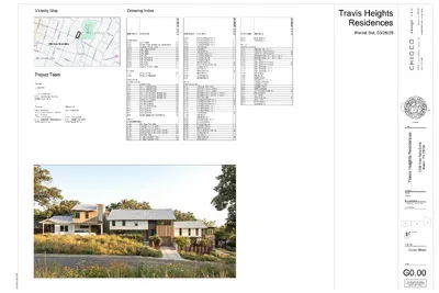
Vicinity Map Drawing Index 1506 East Side Drive Project Team Owner Luxustay LLC - - phone email contact 919.867.9491 Luxustay2@gmail.com Afolabi Anani Architect Structural Chioco Design LLC 1515 E Caeser Chavez St, STE 120 Austin, TX 78703 phone email contact 512.374.0288 contact@chiocodesign.com Jamie Chioco Statix Engineering - - phone email contact 512.222.9849 info@statixeng.com Maxim Shorey Sheet Number Sheet Name 00 GENERAL G0.00 G0.01 G0.10 G0.11 G0.12 G0.13 G0.20 G0.21 G0.22 G0.40 G0.41 G0.42 01 DEMO D1.20 D3.00 Cover Sheet General Notes, Symbols, and Abbreviations Visitability Waiver Exhibit Site Protection Notes ADA Details ADA Details Site Plan Site Plan Exhibits Site Plan Exhibits Wall Types Wall Types Typ Head & Base Details Demolition Plan Demolition Elevations STRUCTURAL 05 STRUCTURAL S0.0 S1.1 S1.2 S1.3 S2.1 S2.2 S2.3 S3.0 S4.0 S4.1 S4.2 S5.0 S5.1 S5.2 S5.3 General Notes Unit 1 Foundation Plan Unit 2 Foundation Plan Unit 3 Foundation Plan Unit 1 Floor and Roof Framing Plans Unit 2 Floor and Roof Framing Plans Unit 3 Floor and Roof Framing Plans Lateral Bracing Plans Foundation Details Foundation Details Pier and Beam Details Framing Details Framing Details Framing Details Lateral bracing and Typical Details UNIT 1 04 ARCHITECTURE A1.10 A1.20 A1.21 A1.30 A1.31 A1.40 A2.00 A2.01 Slab Edge Plan - Unit 1 Floor Plan - Unit 1 - Level 1 Floor Plan - Unit 1 - Level 2 Reflected Ceiling Plan - Unit 1 - Level 1 Reflected Ceiling Plan - Unit 1 - Level 2 Roof Plan - Unit 1 Building Elevations - Unit 1 Building Elevations - Unit 1 I T E s T M R E p - 6 2 / 6 2 3 0 / ● ● ● ● ● ● ● ● ● ● ● ● ● ● ● ● ● ● ● ● ● ● ● ● ● ● ● ● ● ● ● Sheet Number Sheet Name A2.10 A2.11 A2.12 A2.13 A3.00 A4.00 A4.10 A5.01 A5.10 A5.20 A5.30 A6.00 A7.00 A7.02 A7.03 A8.00 A8.01 A9.00 A9.01 Building Sections - Unit 1 Building Sections - Unit 1 Building Sections - Unit 1 Building Sections - Unit 1 Wall Sections Plan Details Section Details Enlarged Stairs - Unit 1 Enlarged Bathrooms Enlarged Kitchens Enlarged Millwork Interior Elevations Door & Window Schedules Window Details Door Details Finish Schedule Finish Plan 01 General Details Millwork Details UNIT 2 04 ARCHITECTURE A1.11 A1.20 A1.21 A1.30 A1.31 A1.40 A2.00 A2.01 A2.02 A2.10 A2.11 A2.12 A3.00 A4.00 A4.10 A5.00 A5.10 A5.20 A5.30 A6.00 A7.00 A7.02 A7.03 A8.00 A8.01 Slab Edge Plan - Unit 2 Floor Plan - Unit 2 - Level 1 Floor Plan - Unit 2 - Level 2 Reflected Ceiling Plan - Unit 2 - Level 1 Reflected Ceiling Plan - Unit 2 - Level 2 Roof Plan - Unit 2 Building Elevations - Unit 2 Building Elevations - Unit 2 Building Elevations - Unit 2 Building Sections - Unit 2 Building Sections - Unit 2 Building Sections - Unit 2 Wall Sections Plan Details Section Details Enlarged Stairs - Unit 2 Enlarged Bathrooms Enlarged Kitchens Enlarged Millwork Interior Elevations Door & Window Schedules Window Details Door Details Finish Schedule Finish Plan 01 I T E s T M R E p - 6 2 / 6 2 3 0 / ● ● ● ● ● ● ● ● ● ● ● I T E s T M R E p - 6 2 / 6 2 3 0 / ● ● ● ● ● ● Sheet Number Sheet Name A9.00 A9.01 General Details Millwork Details UNIT 3 04 ARCHITECTURE A1.12 A1.20 A1.21 A1.30 A1.35 A1.42 A2.05 A2.06 A2.10 A2.11 A2.12 A3.00 A4.00 A4.10 A5.00 A5.10 A5.20 A5.30 A6.00 A7.00 A7.02 A7.03 A8.00 A8.01 A9.00 A9.01 Slab Edge Plan - Unit 3 Floor Plan - Unit 3 - Level 1 Floor Plan - Unit 3 - Level 2 Reflected Ceiling Plan - Unit 3 - Level 1 Reflected Ceiling Plan - Unit 3 - Level 2 Roof Plan - Unit 3 Building Elevations - Unit 3 Building Elevations - Unit 3 Building Sections - Unit 3 Building Sections - Unit 3 Building Sections - Unit 3 Wall Sections Plan Details Section Details Enlarged Stairs - Unit 3 Enlarged Bathrooms Enlarged Kitchens Enlarged Millwork Interior Elevations Door & Window Schedules Window Details Door Details Finish Schedule Finish Plan 01 General Details Millwork Details Travis Heights Residences Permit Set, 03/26/26 03/26/26 project i s e c n e d s e R s t h g e H s v a r T i i e v i r D e d S i t s a E 6 0 5 1 4 0 7 8 7 X T , n i t s u A M P 0 0 : 9 3 : 8 6 2 0 2 / 4 2 / 3 drawn by Author Checker current issue 03/26/26 Permit Set revisions 3 2 1 TRUE NORTH sheet title Cover Sheet sheet G0.00 Caution: do not scale drawings. These drawings are the property of Chioco Design and may only be used in conjunction with this project. c o t t o n s p i n d l e f o u n d I P F 0 . 9 1 ' I P F I P F B Y : H o l t C a r s o n H O L T C A R S O N , I N C . 1 9 0 4 F o r t v i e w R o a d A u s t i n , T e x a s 7 8 7 0 4 ( 5 1 2 ) - 4 4 2 - 0 9 9 0 F i r m R e g i s t r a t i o n N u m b e r 1 0 0 5 0 7 0 0 R e g i s t e r e d P r o f e s s i o n a l L a n d S u r v e y o r N o . 5 1 6 6 G F N o . 2 3 0 5 0 9 5 2 - H A Y T O : L u x u s t a y L L C I n d e p e n d e n c e T i t l e T H I S t h e 1 9 t h d a y o f J U N E , A . D . , 2 0 2 5 . R a t e M a p P a n e l N o . 4 8 4 5 3 C 0 6 0 5 K , d a t e d J a n u a r y 2 2 , 2 0 2 0 . T H E S T A T E O F T E X A S T H E C O U N T Y O F T R A V I S T i t l e R e s o u r c e s G u a r a n t y C o m p a n y P l a i n ) a c c o r d i n g t o t h e F e d e r a l E m e r g e n c y M a n a g e m e n t A g e n c y F l o o d I n s u r a n c e T h i s p r o p e r t y i s w i t h i n Z o n e X ( a r e a s d e t e r m i n e d t o b e o u t s i d e o f t h e 1 0 0 Y e a r F l o o d a n d a C a t e g o r y 6 , C o n d i t i o n 1 , T o p o g r a p h i c S u r v e y . T h e u n d e r s i g n e d d o e s h e r e b y c e r t i f y t h a t a s u r v e y w a s t h i s d a y m a d e o n t h e M a n u a l o f P r a c t i c e r e q u i r e m e n t s f o r a C a t e g o r y 1 A , C o n d i t i o n 3 , L a n d T i t l e S u r v e y , g r o u n d o f t h e p r o p e r t y l e g a l l y d e s c r i b e d h e r e o n a n d i s a c c u r a t e t o t h e b e s t o f m y a b i l i t i e s . T h i s s u r v e y s u b s t a n t i a l l y c o m p l i e s w i t h t h e c u r r e n t T e x a s S o c i e t y o f P r o f e s s i o n a l S u r v e y o r s ( 4 2 0 3 - - T e x a s C e n t r a l Z o n e ) S t a t e P l a n e C o o r d i n a t e S y s t e m . O R I E N T A T I O N N O T E : T h e o r i e n t a t i o n f o r t h i s s u r v e y w a s b a s e d u p o n t h e W N E Demolition Plan General Notes: 1. 2. 3. 4. 5. 6. 7. 8. 9. 10. 11. 12. Keynotes located on this sheet are for this sheet only. The dimensions on this sheet are to face of stud and/or masonry, or centerline of column/beam, unless otherwise noted. If a specific dimension is not provided, contact Chioco Design for clarification. Perform a thorough investigation of conditions where demolition is required and become familiar with the scope of the demolition work required. Field-verify all dimensions prior to demolition to verify extent of demolition will accommodate work. If a discrepancy is identified, notify Chioco Design immediately. All demolition work to be performed in an orderly manner with barricades and cover provided as necessary to protect pedestrians, workmen and adjacent property. Safety standards to be in strict accordance with latest OSHA standards applicable to the work. Procure and pay for all required demolition permits from local authorities. All materials resulting from demolition activities to become the property of the general contractor and shall be disposed of in a legal manner. Exercise all possible caution during demolition activities to prevent damage to existing areas to remain, existing utilities, underground utilities and storm drainage lines, existing drives, sidewalks and adjacent property. Repair or make good any loss or damage as may occur due to demolition activities. Verify with local utilities companies the location of all existing utility lines and services in areas where demolition or new construction work is to be performed. Disconnect any electrical, water, sewer, telephone or other such services as required to facilitate demolition work prior to the commencement of the work. When, during the course of demolition activities, conditions are encountered (i.e. underground utilities, structural components) which could not have been foreseen or not specifically indicated on the drawings, shore or brace to a safe condition or support as required, cease activity and immediately notify the Chioco Design for direction. Refer to standard specifications for additional information and requirements with regard to demolition. Render the area for new construction free and clear of all items that would hinder progress to new work. Remove only enough existing adjacent construction to provide for adequate room for access to new work. Coordinate demolition with all other trades that might be affected. Perform a thorough inspection of all walls to be removed to determine if load bearing prior to demolition work. Procure the services of a structural engineer, if necessary. S 03/26/26 project c o t t o n s p i n d l e f o u n d w m e t e r w a t e r EXISTING HOME TO BE DEMOLISHED STAIRS TO BE DEMOLISHED SITE WORK TO BE DEMOLISHED WALKWAY TO BE DEMOLISHED STONE WALL TO BE DEMOLISHED WALKWAY AND COVERED CONCRETE TO BE DEMOLISHED PLANTER TO BE DEMOLISHED WALL TO BE DEMOLISHED SITE WORK TO BE DEMOLISHED BUILDING AND ASSOCIATED ELEMENTS TO BE DEMOLISHED 8 8 8 8 8 8 8 8 1 G0.30 DRIVEWAY TO BE DEMOLISHED ww m e t e r s w a t e r DRIVEWAY TO BE DEMOLISHED m e t e r l e e c t r i c I P F 8 8 8 8 8 8 8 8 m e t a l b o l t f o u n d S 3 7 ° W 0 . 8 4 ' n o t u s e d b e a r s m a r k e d " E x a c t a " c a p p e d i r o n r o d f o u n d S 4 1 ° W 1 . 4 1 ' n o t u s e d b e a r s m a r k e d " E x a c t a " c a p p e d i r o n r o d f o u n d S t o p s i g n I P F S t o p s i g n I B E G N N N G I electric meter P L A C E O F PLANTERS TO BE DEMOLISHED DRIVEWAY TO BE DEMOLISHED w i r e g u y M P 9 1 : 6 2 : 6 6 2 0 2 / 4 2 / 3 pole Demolition Plan 3/32" = 1'-0" 1 L e g e n d 8 C a l c u l a t e d P o i n t C h a i n L i n k F e n c e W o o d B o a r d F e n c e ( R e c o r d B e a r i n g a n d D i s t a n c e ) O v e r h e a d U t i l i t y L i n e I P F 1 I / 2 r o " n 1 / I 2 r " o n P i p e F o u n d R o d F o u n d i m p r i n t e d w i t h " H o l t I r 1 o / 2 n " R o d S e t w i t h C a r s o n , p l a s t i c c a p I n c . " i s e c n e d s e R s t h g e H s v a r T i i e v i r D e d S i t s a E 6 0 5 1 4 0 7 8 7 X T , n i t s u A drawn by Author Checker current issue 03/26/26 Permit Set revisions sheet title Demolition Plan sheet D1.20 Caution: do not scale drawings. These drawings are the property of Chioco Design and may only be used in conjunction with this project. I P F EXTERIOR VISITABLE ROUTE WAIVER Highest Point: ≥ 518.0' Lowest Point: ≤ 498.0' Distance Between: 165.25' ((518-498) / 165.25')(100) = 12.1% EXTERIOR VISITABLE ROUTE WAIVER Highest Point: ≥ 518.0' Lowest Point: ≤ 498.0' Distance Between: 165.25' ((518-498) / 165.25')(100) = 12.1% PROJECT DESCRIPTION Three-unit residential development located in the Travis Heights Neighborhood. PROJECT DATA Address: Zoning: Legal Description: 1506 East Side Drive SF-3-NCCD-NP 15,075 square feet of land, being all of Lot 2, Block 12R, Subdivision of Block 12M, Block 12Q and Block 12R, of Fairview Park Addition, according to the map or plat thereof recorded in Volume 3 Page 120 of the Plat Records of Travis Country, Texas, together with a portion of that certain (4,180 square feet) as described in deed recrorded in Volume 926 Page 276 of the deed records of Travis Country, Texas, and together with all of that certain (0.002 acre) tract of land as described in deed recorded in Volume 3631 Page 723 of the deed records of Travis County, Texas. FLOOR-TO-AREA (FAR) RATIO CALCULATIONS Site Area: Gross Square Footage 15,075 SF Allowed Proposed Site Total: Unit 1 Total: Unit 2 Total: Unit 3 Total: 0.65 (9,799 SF) 0.56 (8,531 SF) 0.40 (6,030 SF) 0.15 (2,188 SF) 0.40 (6,030 SF) 0.21 (3,183 SF) 0.40 (6,030 SF) 0.20 (3,160 SF) BUILDING COVERAGE CALCULATIONS Site Area: Building Coverage Site Total: Unit 1 Total: Unit 2 Total: Unit 3 Total: 15,075 SF Allowed Proposed 0.40 (6,030 SF) 0.32 (4,801 SF) - - - 1,301 SF 1,756 SF 1,744 SF IMPERVIOUS COVERAGE CALCULATIONS Site Area: 15,075 SF Allowed Impervious Coverage: Proposed Impervious Coverage: 45% (6,783.75 SF) 45% (6,783.75 SF) Building Coverage: Driveways: Site Walls: AC/Equipment Pads: Uncovered Wood Deck: Pool Coping: Total Impervious Cover: 03/26/26 project i s e c n e d s e R s t h g e H s v a r T i i e v i r D e d S i t s a E 6 0 5 1 4 0 7 8 7 X T , n i t s u A M P 6 0 : 6 2 : 6 6 2 0 2 / 4 2 / 3 drawn by Author Checker current issue 03/26/26 Permit Set revisions sheet title Visitability Waiver Exhibit sheet G0.10 Caution: do not scale drawings. These drawings are the property of Chioco Design and may only be used in conjunction with this project. West-Facing View from East Side Drive design LLCCHIOCOARC Meeting Materials | 514 E Monroe St B Y : H o l t C a r s o n H O L T C A R S O N , I N C . 1 9 0 4 F o r t v i e w R o a d A u s t i n , T e x a s 7 8 7 0 4 ( 5 1 2 ) - 4 4 2 - 0 9 9 0 F i r m R e g i s t r a t i o n N u m b e r 1 0 0 5 0 7 0 0 R e g i s t e r e d P r o f e s s i o n a l L a n d S u r v e y o r N o . 5 1 6 6 T H I S t h e 1 9 t h d a y o f J U N E , A . D . , 2 0 2 5 . R a t e M a p P a n e l N o . 4 8 4 5 3 C 0 6 0 5 K , d a t e d J a n u a r y 2 2 , 2 0 2 0 . T H E S T A T E O F T E X A S T H E C O U N T Y O F T R A V I S T i t l e R e s o u r c e s G u a r a n t y C o m p a n y P l a i n ) a c c o r d i n g t o t h e F e d e r a l E m e r g e n c y M a n a g e m e n t A g e n c y F l o o d I n s u r a n c e T h i s p r o p e r t y i s w i t h i n Z o n e X ( a r e a s d e t e r m i n e d t o b e o u t s i d e o f t h e 1 0 0 Y e a r F l o o d a n d a C a t e g o r y 6 , C o n d i t i o n 1 , T o p o g r a p h i c S u r v e y . T h e u n d e r s i g n e d d o e s h e r e b y c e r t i f y t h a t a s u r v e y w a s t h i s d a y m a d e o n t h e M a n u a l o f P r a c t i c e r e q u i r e m e n t s f o r a C a t e g o r y 1 A , C o n d i t i o n 3 , L a n d T i t l e S u r v e y , g r o u n d o f t h e p r o p e r t y l e g a l l y d e s c r i b e d h e r e o n a n d i s a c c u r a t e t o t h e b e s t o f m y a b i l i t i e s . T h i s s u r v e y s u b s t a n t i a l l y c o m p l i e s w i t h t h e c u r r e n t T e x a s S o c i e t y o f P r o f e s s i o n a l S u r v e y o r s G F N o . 2 3 0 5 0 9 5 2 - H A Y T O : L u x u s t a y L L C I n d e p e n d e n c e T i t l e Level 1 Floor Plan Scale: 1’ = 1/16” ( 4 2 0 3 - - T e x a s C e n t r a l Z o n e ) S t a t e P l a n e C o o r d i n a t e S y s t e m . O R I E N T A T I O N N O T E : T h e o r i e n t a t i o n f o r t h i s s u r v e y w a s b a s e d u p o n t h e W N S E T E E R T E S O R N O T M S A E EAST SIDE DRIVE Level 1 Level 2 Total House I 1,250 SF 700 SF 1,950 SF House II 1,800 SF 1,450 SF 3,250 SF House III 1,800 SF 1,450 SF 3,250 SF 1 1st Floor F.F.E. - P4 1/16" = 1'-0" design LLCCHIOCOARC Meeting Materials | 514 E Monroe St B Y : H o l t C a r s o n H O L T C A R S O N , I N C . 1 9 0 4 F o r t v i e w R o a d A u s t i n , T e x a s 7 8 7 0 4 ( 5 1 2 ) - 4 4 2 - 0 9 9 0 F i r m R e g i s t r a t i o n N u m b e r 1 0 0 5 0 7 0 0 R e g i s t e r e d P r o f e s s i o n a l L a n d S u r v e y o r N o . 5 1 6 6 T H I S t h e 1 9 t h d a y o f J U N E , A . D . , 2 0 2 5 . R a t e M a p P a n e l N o . 4 8 4 5 3 C 0 6 0 5 K , d a t e d J a n u a r y 2 2 , 2 0 2 0 . T H E S T A T E O F T E X A S T H E C O U N T Y O F T R A V I S T i t l e R e s o u r c e s G u a r a n t y C o m p a n y P l a i n ) a c c o r d i n g t o t h e F e d e r a l E m e r g e n c y M a n a g e m e n t A g e n c y F l o o d I n s u r a n c e T h i s p r o p e r t y i s w i t h i n Z o n e X ( a r e a s d e t e r m i n e d t o b e o u t s i d e o f t h e 1 0 0 Y e a r F l o o d a n d a C a t e g o r y 6 , C o n d i t i o n 1 , T o p o g r a p h i c S u r v e y . T h e u n d e r s i g n e d d o e s h e r e b y c e r t i f y t h a t a s u r v e y w a s t h i s d a y m a d e o n t h e M a n u a l o f P r a c t i c e r e q u i r e m e n t s f o r a C a t e g o r y 1 A , C o n d i t i o n 3 , L a n d T i t l e S u r v e y , g r o u n d o f t h e p r o p e r t y l e g a l l y d e s c r i b e d h e r e o n a n d i s a c c u r a t e t o t h e b e s t o f m y a b i l i t i e s . T h i s s u r v e y s u b s t a n t i a l l y c o m p l i e s w i t h t h e c u r r e n t T e x a s S o c i e t y o f P r o f e s s i o n a l S u r v e y o r s G F N o . 2 3 0 5 0 9 5 2 - H A Y T O : L u x u s t a y L L C I n d e p e n d e n c e T i t l e Level 2 Floor Plan Scale: 1’ = 1/16” Scale: 1’ = 1/16” ( 4 2 0 3 - - T e x a s C e n t r a l Z o n e ) S t a t e P l a n e C o o r d i n a t e S y s t e m . O R I E N T A T I O N N O T E : T h e o r i e n t a t i o n f o r t h i s s u r v e y w a s b a s e d u p o n t h e W N S E T T E E E E R R T T E S E S O O R R N N O O T M T M S S A A E E EAST SIDE DRIVE EAST SIDE DRIVE Level 1 Level 2 Total House I 1,250 SF 700 SF 1,950 SF House II 1,800 SF 1,450 SF 3,250 SF House III 1,800 SF 1,450 SF 3,250 SF 1 1st Floor F.F.E. - P4 Copy 1 1/16" = 1'-0" design LLCCHIOCOARC Meeting Materials | 514 E Monroe St 18' - 11 1/2" 4' - 8 1/2" 19' - 3 1/8" " 1 1 - ' 6 " 4 / 3 8 - ' 2 1 ? " 4 / 1 9 - ' 2 1 2x6 Blocking, Centered at 34" Above FFE Bedroom 1 2'-10" x 7'-0" Door 30"x30" Closet 1 Entry Vestibule Powder Room 518' - 3" 3'-6" x 8'-0" Opening 32" Clear Vistable Path Bathroom 1 Stairs - 3'-0" x 7'-0" Door - No Step Threshold - 1/2" Drop at Entry 36"x36" UP Exterior Vistable Route Waived; REF G0.10 518' - 2 1/2" Kitchen W/D CL UP Living Dining A2.00 1 6' - 4 1/2" 27' - 2 1/2" 8' - 5 1/8" 7 5/8" 5' - 9" UP " 8 / 1 6 " 8 5 / 0 1 - ' 2 1 " 2 / 1 2 - ' 8 1 2 A2.13 1 A2.13 1 A2.01 2 A2.12 Sim 1 A2.12 1 A2.10 2 A2.10 4 A2.00 1 A2.11 2 A2.11 M P 0 2 : 6 2 : 6 6 2 0 2 / 4 2 / 3 1 Floor Plan - Unit 1 - Level 1 1/4" = 1'-0" Floor Plan General Notes: 1. 2. 3. 4. 5. 6. 7. 8. 9. 10. Keynotes located on this sheet are for this sheet only. The dimensions on this sheet are to face of stud, concrete wall, and/or masonry, or centerline of column/beam, unless otherwise noted. Walls intersecting at angles other than 90 degrees are dimensioned to the outside corner of stud framing, concrete wall, and/or masonry Interior furr outs on exterior walls are tagged as interior partitions If a specific dimension is not provided, contact Chioco Design for clarification. Provide portable fire extinguishers per local requirements. Coordinate final location with Chioco Design. Install all products per manufacturer's recommendations. Provide fire-rated wood blocking as required. Field-verify all benchmark elevations. TBD Field-verify all dimensions prior to construction and/or installation of any equipment, accessories, etc. If a discrepancy is identified, notify Chioco Design immediately. Walls Existing New <<< Indicates Sheet Keynote on Plan 03/26/26 project i s e c n e d s e R s t h g e H s v a r T i i e v i r D e d S i t s a E 6 0 5 1 4 0 7 8 7 X T , n i t s u A drawn by Author Checker current issue 03/26/26 Permit Set revisions sheet title Floor Plan - Unit 1 - Level 1 sheet A1.20 Caution: do not scale drawings. These drawings are the property of Chioco Design and may only be used in conjunction with this project. 6 1/8" 9' - 11 7/8" 9' - 5 5/8" 9' - 5 5/8" " 8 7 / 0 1 - ' 5 1 " 4 / 1 0 1 - ' 5 1 " 8 / 1 6 Den Bath 2 Bedroom 2 Stairs UP Closet 3 Bathroom 3 Bedroom 3 UP 4' - 8 5/8" 7' - 3 1/2" 7' - 7 3/8" 3' - 5 1/8" 7 5/8" 5' - 9" " 8 / 1 6 " 8 5 / 0 1 - ' 2 1 " 4 / 1 0 1 - ' 6 " 4 / 1 4 - ' 1 1 2 A2.13 1 A2.13 1 A2.01 2 A2.12 1 A2.12 1 A2.10 2 A2.10 1 A2.11 2 A2.11 M P 1 2 : 6 2 : 6 6 2 0 2 / 4 2 / 3 1 Floor Plan - Unit 1 - Level 2 1/4" = 1'-0" Floor Plan General Notes: 1. 2. 3. 4. 5. 6. 7. 8. 9. 10. Keynotes located on this sheet are for this sheet only. The dimensions on this sheet are to face of stud, concrete wall, and/or masonry, or centerline of column/beam, unless otherwise noted. Walls intersecting at angles other than 90 degrees are dimensioned to the outside corner of stud framing, concrete wall, and/or masonry Interior furr outs on exterior walls are tagged as interior partitions If a specific dimension is not provided, contact Chioco Design for clarification. Provide portable fire extinguishers per local requirements. Coordinate final location with Chioco Design. Install all products per manufacturer's recommendations. Provide fire-rated wood blocking as required. Field-verify all benchmark elevations. TBD Field-verify all dimensions prior to construction and/or installation of any equipment, accessories, etc. If a discrepancy is identified, notify Chioco Design immediately. Walls Existing New <<< Indicates Sheet Keynote on Plan 03/26/26 project i s e c n e d s e R s t h g e H s v a r T i i e v i r D e d S i t s a E 6 0 5 1 4 0 7 8 7 X T , n i t s u A drawn by Author Checker current issue 03/26/26 Permit Set revisions sheet title Floor Plan - Unit 1 - Level 2 sheet A1.21 Caution: do not scale drawings. These drawings are the property of Chioco Design and may only be used in conjunction with this project. RF-1 RF-1 Unit 1 - Max Building Height 547' - 1 1/2" RF-1 Unit 1 - Roof 540' - 3" Elevations & Sections General Notes: 1. 2. 3. 4. 5. 6. Keynotes located on this sheet are for this sheet only. The dimensions on this sheet are to the face of finish material or edge of masonry, unless noted otherwise. If a specific dimension is not provided, contact Chioco Design for clarification. Field-verify all existing dimensions prior to construction and/or installation of any equipment, accessories, etc. If a discrepancy is identified, notify Chioco Design immediately. Building Elevations are provided for reference only. For additional information, refer to Floor Plans, Building Sections, Wall Sections, and Door & Window Elevations. All glass to be tempered as required by local code. <<< Indicates Sheet Keynote on Plan t i h g e H g n d i l i u B x a M " 4 1 / 1 - ' 1 3 " 0 - ' 1 1 " 0 - ' 1 1 PT-1 PT-1 PT-1 RF-2 1L WD-2 1K 1M 1N 1C WD-1 1C RF-1 WD-2 WD-2 4 Building Elevation - Unit 1 - East 1/4" = 1'-0" PT-1 CONC. 2 PT-1 STL CONC. 1 i t h g e H g n d i l i u B x a M " 4 / 1 1 - ' 1 3 1J WD-2 WD-2 1K WD-1 RF-2 1B 1B 1B PT-1 PT-1 " 0 - ' 1 1 " 0 - ' 1 1 1H 1A WD-1 EXISTING WINDOW TO BE RESTORED AND REUSED PT-1 CONC. 2 PT-1 CONC. 2 CONC. 1 STL M P 2 2 : 6 2 : 6 6 2 0 2 / 4 2 / 3 1 Building Elevation - Unit 1 - South 1/4" = 1'-0" Unit 1 - Level 2 F.F.E. 529' - 3" Unit 1 - 1st Floor F.F.E. 518' - 3" Unit 1 - AAG 516' - 0" Unit 1 - Max Building Height 547' - 1 1/2" Unit 1 - Roof 540' - 3" Unit 1 - Level 2 F.F.E. 529' - 3" Unit 1 - 1st Floor F.F.E. 518' - 3" Unit 1 - AAG 516' - 0" 03/26/26 project i s e c n e d s e R s t h g e H s v a r T i i e v i r D e d S i t s a E 6 0 5 1 4 0 7 8 7 X T , n i t s u A drawn by Author Checker current issue 03/26/26 Permit Set revisions sheet title Building Elevations - Unit 1 sheet A2.00 Caution: do not scale drawings. These drawings are the property of Chioco Design and may only be used in conjunction with this project. t i h g e H g n d i l i u B x a M " 4 1 / 1 - ' 1 3 RF-1 1G 1R 1G WD-2 1F 1G " 0 - ' 1 1 " 0 - ' 1 1 RF-2 WD-1 2 Building Elevation - Unit 1 - West 1/4" = 1'-0" i t h g e H g n d i l i u B x a M " 4 / 1 1 - ' 1 3 " 0 - ' 1 1 " 0 - ' 1 1 STL PT-1 WD-2 1P CONC. 2 1Q WD-2 1E M P 3 2 : 6 2 : 6 6 2 0 2 / 4 2 / 3 1 Building Elevation - Unit 1 - North 1/4" = 1'-0" Unit 1 - Max Building Height 547' - 1 1/2" Elevations & Sections General Notes: 1. 2. 3. 4. 5. 6. Keynotes located on this sheet are for this sheet only. The dimensions on this sheet are to the face of finish material or edge of masonry, unless noted otherwise. If a specific dimension is not provided, contact Chioco Design for clarification. Field-verify all existing dimensions prior to construction and/or installation of any equipment, accessories, etc. If a discrepancy is identified, notify Chioco Design immediately. Building Elevations are provided for reference only. For additional information, refer to Floor Plans, Building Sections, Wall Sections, and Door & Window Elevations. All glass to be tempered as required by local code. Unit 1 - Roof 540' - 3" <<< Indicates Sheet Keynote on Plan Unit 1 - Level 2 F.F.E. 529' - 3" Unit 1 - 1st Floor F.F.E. 518' - 3" Unit 1 - AAG 516' - 0" Unit 1 - Max Building Height 547' - 1 1/2" Unit 1 - Roof 540' - 3" PT-1 Unit 1 - Level 2 F.F.E. 529' - 3" Unit 1 - 1st Floor F.F.E. 518' - 3" Unit 1 - AAG 516' - 0" 03/26/26 project i s e c n e d s e R s t h g e H s v a r T i i e v i r D e d S i t s a E 6 0 5 1 4 0 7 8 7 X T , n i t s u A drawn by Author Checker current issue 03/26/26 Permit Set revisions sheet title Building Elevations - Unit 1 sheet A2.01 Caution: do not scale drawings. These drawings are the property of Chioco Design and may only be used in conjunction with this project. Type Mark Manufacturer Series Width Height Head Detail Sill Detail Jamb Detail Glazing Type Comments Window Schedule - Unit 1 1K 1K 1L 1M 1N 1J 1H 1E 1Q 1G 1G 1R 1G 1F Western Western Western Western Western Western Western Western Western Western Western Western Western Western TBD TBD TBD TBD TBD TBD TBD TBD TBD TBD TBD TBD TBD TBD 2' - 6" 2' - 6" 4' - 8" 3' - 3" 3' - 6" 3' - 0" 4' - 0" 10' - 10" 3' - 6" 9' - 5" 9' - 5" 5' - 6" 9' - 5" 5' - 5" 7' - 0" 7' - 0" 7' - 0" 15' - 0" 6' - 0" 8' - 6" 6' - 0" 2' - 6" 2' - 6" 2' - 6" 2' - 6" 2' - 6" 2' - 6" 2' - 6" Casement to meet egress requirements Casement to meet egress requirements Casement to meet egress requirements Glazing Specifications: 1. All glass to be GL-1 unless noted otherwise. GL-1 1" Insulated Glass Unit Guardian Manufacturer: Outboard Lite: 1/4" Clear Low-E Coating: SNX 51/23 Airspace: Inboard Lite: SHGC: VLT: U Factor: 1/2", Black Spacer 1/4" Clear 0.23 51% 0.29 GL-2 1" Insulated Glass Unit - Frosted Guardian Manufacturer: Outboard Lite: 1/4" Clear Low-E Coating: SNX 51/23 Airspace: Inboard Lite: SHGC: VLT: U Factor: 1/2", Black Spacer 1/4" Clear 0.23 51% 0.29 Doors & Windows General Notes: 1. 2. 3. 4. 5. 6. 7. 8. 9. Keynotes located on this sheet are for this sheet only. The dimensions on this sheet are to the face of finish material or edge of masonry, unless noted otherwise. If a specific dimension is not provided, contact Chioco Design for clarification. Install all products per manufacturer's recommendations. All glass to be tempered as required by local code. Verify finish of all new hardware with Chioco Design. All entry doors shall have lock cylinders with thumb latch on inside. Refer to Hardware Schedule for further information. Supply Owner/Tenant with a total of 5 keys for all keyed hardware. Door closers shall take at least 3 seconds to move from 70˚ to 3"from latch. (ADD BELOW AS APPLICABLE) 1. 2. 3. 4. 5. 6. On door schedule – move to template Sign located on front entry door(s) stating, "this door is to remain unlocked while the building is occupied per section 1008.1.9.3 Substitutes will be accepted for any door hardware by prior owner approval only All new hollow metal door and metal frames to be by republic, ceco, curries or equal. Doors to be 18 ga., flush panel, factory primed. Frames ot be 16 ga. Factory primed, with welded corners, u.n.o., paint as scheduled, exterior face of ext. Hm doors to match building standards. All interior surfaces of flush panel h.m. Doors and frames (u.n.o.), shall be primed, ready for paint finish All doors shall comply with ANSI a117.1.13.9, latest ed. Door Schedule Remarks: 1. 2. 3. Verify size of all custom doors in field. - - Door Panel Types: " 1 - ' 2 " 7 - ' 3 Coord Panic Bar W/Lite 4" " 0 1 - ' 2 Varies 2'-10" max " 0 - ' 3 i n M " 0 1 Hardware Schedule: FLUSH F NARROW LITE HALF GLASS FULL GLASS N 100 SQ IN MAX G 1286 SQ IN MAX FG 03/26/26 project 1 2 3 4 - Lockset: - Pull: - Hinges: - Closer: - Stop: Sweep: - Weatherstripping: - - Threshold: - Exit Devices: - Lockset: - Pull: - Hinges: - Closer: - Stop: - Sweep: Weatherstripping: - - Threshold: - Exit Devices: Lockset: - Pull: - Hinges: - Closer: - Stop: - - Sweep: Weatherstripping: - - Threshold: - Exit Devices: - Lockset: - Pull: - Hinges: - Closer: - Stop: Sweep: - Weatherstripping: - - Threshold: - Exit Devices: X A M " 4 3 T H F L E H S LOUVERED L DUTCH D Door Frame Types: i s e c n e d s e R s t h g e H s v a r T i i e v i r D e d S i t s a E 6 0 5 1 4 0 7 8 7 X T , n i t s u A RABBETED A DOUBLE EGRESS B CASED C RECESSED PIN GUIDE TRACK SYSTEM @ SLIDING PARTITION SWING PANEL SLIDE/ SWING PANEL "SO" "SX" drawn by Author Checker current issue 03/26/26 Permit Set revisions M P 3 2 : 6 2 : 6 6 2 0 2 / 4 2 / 3 General Abbreviations: AL1 AL2 BR HCWD HM Ll + PH PLAM PNT PW SCWD STF SO SR SST SX ANODIZED ALUMINUM BRONZED ALUMINUM BALLISTICS RESISTANT HOLLOW METAL DOOR HOLLOW CORE WOOD HOLLOW METAL LEAD LINED REFER TO MANUFACTURER PACKAGE HEIGHT PLASTIC LAMINATE FACED DOOR PAINTED FINISH PACKAGE WIDTH SOLID CORE WOOD STAINED FINISH SWING OUT, SIDELIGHT SMOKE RESISTANT STAINLESS STEEL FINISH SWING SLIDE PANEL sheet title Door & Window Schedules sheet A7.00 Caution: do not scale drawings. These drawings are the property of Chioco Design and may only be used in conjunction with this project. FOUR SIDED FRAME @ ROOF D 3'RECESS TRACK @ SIDELITE 3' TRACKLESS SLIDING DOOR OPENING E Category (Hide) Mark Description Manufacturer Product Finish Comments PRODUCT AND FINISH KEY SCHEDULE Finish Plan General Notes: Concrete Concrete Granite Granite Masonry Masonry Metal Metal CONC-1 Board-formed concrete DG-1 Decomposed Granite STN-1 Limestone Pool Coping MTL-1 3/16" Plate Steel Siding Metal MTL-2 Painted Break Metal Paint Paint Paint Paint Paint Paint Roofing Roofing PNT-1 PNT-2 PNT-3 PNT-4 PNT-5 Interior Paint Interior Paint Interior Paint Interior Paint Interior Paint RF-1 Standing Seam Metal Roof Roofing RF-2 Asphault Shingle Roof to Match Existing TBD - TBD High-Performan ce Zinc Primer; Paint-TBD High-Performan ce Zinc Primer; Paint-TBD Sherwin Williams Sherwin Williams Sherwin Williams Sherwin Williams Sherwin Williams SW 7005 Pure White SW 7757 High Reflective White SW 7570 Egret White SW 6991 Black Magic Eggshell Flat Eggshell Eggshell Field Paint Ceilings To Match RR Tile Match Dark Metal Stucco Stucco STU-1 3-Part Stucco La Habra Central Texas Metal Roofing Supply TBD ShurLoc 175 TBD AZ-55 Acrylic Galvalume TBD TBD Weather Barrier Weather Barrier Weather Barrier Weather Barrier Weather Barrier Weather Barrier WB-1 WB-2 WB-3 WB-4 WB-5 Weather Barrier, Exterior Walls Dupont Corporation Tyvek, Fluid Applied WB 25 Mil Wet Thickness, Silyl-Terminated Polyether Weather Barrier, Under Slab Barrier W.R. Meadows Corporation Sealtight Assembly 15 Mil Material Thickness. Polyolifin Resin Weather Barrier, Drainage Mat, Patio Mapei Corporation Mapedrain 30 Weather Barrier, Drainage Mat, Patio Schluter Systems, Inc. DITRA-DRAIN Use with Mapebond 710 Thin Set Drainage Mat. TPO, 60 Mil Wood Wood Wood Wood Wood Wood WD-1 WD-2 2 1/2" Tear Drop Siding to Match Existing 6" Tongue & Groove Siding TBD Delta Millworks WD-3 6" Tongue & Groove Siding Delta Millworks TBD Accoya Accoya WD-4 WD-5 Wood Decking 6" Accoya S4S Fencing Delta Millworks Delta Millworks Accoya Decking Accoya Paint - TBD Barnwood - Ivory Smooth - Delta Black Palomino-S Barnwood - Ivory 1 1/2" x 1 1/2" Battens; Spaced 3'-0" O.C. Fencing to match siding M P 4 2 : 6 2 : 6 6 2 0 2 / 4 2 / 3 1. 2. 3. 4. 5. 6. 7. 8. 9. 10. 11. 12. Keynotes located on this sheet are for this sheet only. The dimensions on this sheet are to the face of finish material or edge of masonry, unless noted otherwise. If a specific dimension is not provided, contact Chioco Design for clarification. Install all products per manufacturer's recommendations. Provide adequate protection of finish surfaces during installation. Install taped and secured Ram Board on finishes that are under/near ongoing trade work. Coordinate all grout color selections with Chioco Design. Provide a Level 4 finish at all painted gypsum board walls. Provide a Level 5 finish at gypsum board ceilings, plaster finishes, wallpaper applications, gloss paint finishes, or at points of wallwash or coved lighting. Provide samples for all finishes as specified, to be reviewed and approved by Chioco Design. Ensure timely approval of long-lead finish materials. Interior Paint: All Walls to be eggshell finish. All ceilings to be flat finish. Paint on millwork and trim to be semi-gloss finish. Unless noted otherwise. All painted mild steel to receive 2-part DTM paint, finish a indicated. All painted CMU or Stucco to recevie Elastomeric paint, finish as scheduled. Al Kitchen/BOH Quarry Tile Flooring to receive Laticrete Spectralock 2000 IG Epoxy Grut, Color Black. Sealed per manufacture's recommendation. Room Finish Tag Legend CEILING FINISH WALL FINISH BASE FINISH FLOOR FINISH COUNTERTOP FINISH CABINET FINISH Millwork Tag Material Transition Tag FLOOR FINISH 1 FLOOR FINISH 2 Substrate Schedule Non-Wet Wall Locations 5/8" Gypsum Board Tile Walls 5/8" Hardi-Board / Durock Wet Walls / Restroom Walls 5/8" Hardi-Board / Durock behind tile finishes 5/8" Moisture-Resistant Gypsum Board at walls and ceiling Sound Batt Insulation at all Restroom Walls FRP Walls 5/8" Fiberock installed up to 48" AFF. 5/8" plywood above (fire rated where required). Install blocking as required for wall shelving (fire rated where required). Refer to blocking schedule on kitchen equipment drawings where provided. Wood Finished Walls 5/8" min Plywood Sheathing, fire-treated as required Plaster Finished Walls 5/8" DensGlass Gold under plaster skim coat as scheduled Stone Veneer Walls 5/8" DensGlass Gold Stucco Finished Walls 5/8" DensGlass Gold at Exterior Stucco 5/8" DensGlass Gold at Interior Stucco 03/26/26 project i s e c n e d s e R s t h g e H s v a r T i i e v i r D e d S i t s a E 6 0 5 1 4 0 7 8 7 X T , n i t s u A drawn by Author Checker current issue 03/26/26 Permit Set revisions Finish Schedule sheet title sheet A8.00 Caution: do not scale drawings. These drawings are the property of Chioco Design and may only be used in conjunction with this project. " 0 - ' 3 / " 8 3 7 - ' 8 " 0 - ' 7 1 " 8 / 1 6 " 8 / 5 2 - ' 4 " 9 - ' 3 " 8 / 7 5 - ' 4 " 8 / 5 0 - ' 0 1 " 8 / 7 9 - ' 2 A2.00 1 UP A2.02 1 8' - 9 1/4" 17' - 10" Kitchen Dining 9' - 9 7/8" 3' - 6 1/8" Living 2 A2.01 3 A2.01 A2.01 4 Pool 510' - 11 1/2" 511' - 0" - 3'-6" x 9'-0" Door - No Step Threshold - 1/2" Drop at Entry 7 1/2" 20' - 7 1/4" 21' - 7 1/4" 36"x36" 32" Clear Vistable Path Exterior Vistable Route Waived; REF G0.10 4' - 9 1/2" Entry 3'-0" x 7'-0" Door 30"x30" 2x6 Blocking, Centered at 34" Above FFE Powder Room Garage -6' - 0" Bedroom 1 Bathroom 1 UP Closet 1 10" 15' - 7 1/4" 4' - 0 7/8" 7 5/8" 24' - 6 1/2" 10' - 7 1/2" 1 A2.10 2 A2.00 2 A2.10 " 8 7 / 7 - ' 3 1 " 2 / 1 7 " 2 / 1 4 - ' 5 1 " 8 / 1 8 - ' 3 " 2 / 1 0 - ' 6 1 " 8 / 5 9 1 A2.12 2 A2.11 1 A2.01 1 A2.11 M P 5 2 : 6 2 : 6 6 2 0 2 / 4 2 / 3 1 Floor Plan - Unit 2 - Level 1 1/4" = 1'-0" Floor Plan General Notes: 1. 2. 3. 4. 5. 6. 7. 8. 9. 10. Keynotes located on this sheet are for this sheet only. The dimensions on this sheet are to face of stud, concrete wall, and/or masonry, or centerline of column/beam, unless otherwise noted. Walls intersecting at angles other than 90 degrees are dimensioned to the outside corner of stud framing, concrete wall, and/or masonry Interior furr outs on exterior walls are tagged as interior partitions If a specific dimension is not provided, contact Chioco Design for clarification. Provide portable fire extinguishers per local requirements. Coordinate final location with Chioco Design. Install all products per manufacturer's recommendations. Provide fire-rated wood blocking as required. Field-verify all benchmark elevations. TBD Field-verify all dimensions prior to construction and/or installation of any equipment, accessories, etc. If a discrepancy is identified, notify Chioco Design immediately. Walls Existing New <<< Indicates Sheet Keynote on Plan 03/26/26 project i s e c n e d s e R s t h g e H s v a r T i i e v i r D e d S i t s a E 6 0 5 1 4 0 7 8 7 X T , n i t s u A drawn by Author Checker current issue 03/26/26 Permit Set revisions sheet title Floor Plan - Unit 2 - Level 1 sheet A1.20 Caution: do not scale drawings. These drawings are the property of Chioco Design and may only be used in conjunction with this project. 1 A2.10 2 A2.10 A2.02 1 15' - 4 1/4" 7 1/2" 7' - 8" 7' - 7 3/4" 6' - 10 3/4" A2.00 1 / " 8 5 6 - ' 4 / " 4 3 4 - ' 8 " 4 / 1 1 1 - ' 9 " 8 / 7 2 - ' 7 " 2 / 1 5 - ' 8 " 8 / 3 4 - ' 2 1 " 8 / 1 6 Closet 2 Bath 2 Bedroom 2 Bathroom 3 1' - 11 1/8" Closet 3 2 A2.01 3 A2.01 A2.01 4 Pool Bedroom 4 Bedroom 3 Den UP Stairs Closet 4 Bath 4 1' - 1" 4' - 11 7/8" 10' - 7 3/8" 4' - 8 1/2" 24' - 6 1/2" 2 A2.00 " 2 / 1 1 1 " 4 1 / 4 - ' 1 1 " 4 / 3 9 - ' 7 1 " 4 / 3 9 - ' 0 1 1 A2.12 2 A2.11 1 A2.01 1 A2.11 M P 6 2 : 6 2 : 6 6 2 0 2 / 4 2 / 3 1 Floor Plan - Unit 2 - Level 2 1/4" = 1'-0" Floor Plan General Notes: 1. 2. 3. 4. 5. 6. 7. 8. 9. 10. Keynotes located on this sheet are for this sheet only. The dimensions on this sheet are to face of stud, concrete wall, and/or masonry, or centerline of column/beam, unless otherwise noted. Walls intersecting at angles other than 90 degrees are dimensioned to the outside corner of stud framing, concrete wall, and/or masonry Interior furr outs on exterior walls are tagged as interior partitions If a specific dimension is not provided, contact Chioco Design for clarification. Provide portable fire extinguishers per local requirements. Coordinate final location with Chioco Design. Install all products per manufacturer's recommendations. Provide fire-rated wood blocking as required. Field-verify all benchmark elevations. TBD Field-verify all dimensions prior to construction and/or installation of any equipment, accessories, etc. If a discrepancy is identified, notify Chioco Design immediately. Walls Existing New <<< Indicates Sheet Keynote on Plan 03/26/26 project i s e c n e d s e R s t h g e H s v a r T i i e v i r D e d S i t s a E 6 0 5 1 4 0 7 8 7 X T , n i t s u A drawn by Author Checker current issue 03/26/26 Permit Set revisions sheet title Floor Plan - Unit 2 - Level 2 sheet A1.21 Caution: do not scale drawings. These drawings are the property of Chioco Design and may only be used in conjunction with this project. t i h g e H g n d i l i u B x a M " 2 1 / 0 - ' 0 3 RF-1 WD-2 WD-2 CONC-1 CONC-1 " 0 - ' 1 1 " 0 - ' 1 1 2M WD-2 MTL-1 2C MTL-1 2C MTL-1 2 Building Elevation - Unit 2 - North 1/4" = 1'-0" RF-1 2K 2K 2K STU-1 WD-3 2B 2B WD-3 WD-2 " 0 - ' 1 1 " 0 - ' 1 1 STU-1 CONC-1 i t h g e H g n d i l i u B x a M " 2 / 1 0 - ' 0 3 M P 7 2 : 6 2 : 6 6 2 0 2 / 4 2 / 3 1 Building Elevations - Unit 2 - East 1/4" = 1'-0" Unit 2 - Max Building Height 539' - 0 1/2" Unit 2 - Roof 533' - 0" Unit 2 - 2nd Floor F.F.E. 522' - 0" Unit 2 - 1st Floor F.F.E. 511' - 0" Unit 2 - AAG 509' - 0" Unit 2 - Max Building Height 539' - 0 1/2" Unit 2 - Roof 533' - 0" Unit 2 - 2nd Floor F.F.E. 522' - 0" Unit 2 - 1st Floor F.F.E. 511' - 0" Unit 2 - AAG 509' - 0" Elevations & Sections General Notes: 1. 2. 3. 4. 5. 6. Keynotes located on this sheet are for this sheet only. The dimensions on this sheet are to the face of finish material or edge of masonry, unless noted otherwise. If a specific dimension is not provided, contact Chioco Design for clarification. Field-verify all existing dimensions prior to construction and/or installation of any equipment, accessories, etc. If a discrepancy is identified, notify Chioco Design immediately. Building Elevations are provided for reference only. For additional information, refer to Floor Plans, Building Sections, Wall Sections, and Door & Window Elevations. All glass to be tempered as required by local code. <<< Indicates Sheet Keynote on Plan 03/26/26 project i s e c n e d s e R s t h g e H s v a r T i i e v i r D e d S i t s a E 6 0 5 1 4 0 7 8 7 X T , n i t s u A drawn by Author Checker current issue 03/26/26 Permit Set revisions sheet title Building Elevations - Unit 2 sheet A2.00 Caution: do not scale drawings. These drawings are the property of Chioco Design and may only be used in conjunction with this project. " 0 - ' 1 1 " 0 - ' 1 1 2P 2Q 2E 2F Unit 2 - Max Building Height 539' - 0 1/2" Unit 2 - Max Building Height 539' - 0 1/2" Unit 2 - Roof 533' - 0" Unit 2 - Roof 533' - 0" Elevations & Sections General Notes: 1. 2. 3. 4. 5. 6. Keynotes located on this sheet are for this sheet only. The dimensions on this sheet are to the face of finish material or edge of masonry, unless noted otherwise. If a specific dimension is not provided, contact Chioco Design for clarification. Field-verify all existing dimensions prior to construction and/or installation of any equipment, accessories, etc. If a discrepancy is identified, notify Chioco Design immediately. Building Elevations are provided for reference only. For additional information, refer to Floor Plans, Building Sections, Wall Sections, and Door & Window Elevations. All glass to be tempered as required by local code. <<< Indicates Sheet Keynote on Plan t i h g e H g n d i Unit 2 - 2nd Floor F.F.E. 522' - 0" l i u B x a M " 2 1 / 0 - ' 0 3 Unit 2 - 1st Floor F.F.E. 511' - 0" Unit 2 - AAG 509' - 0" " 0 - ' 1 1 " 0 - ' 1 1 Unit 2 - 2nd Floor F.F.E. 522' - 0" Unit 2 - 1st Floor F.F.E. 511' - 0" Unit 2 - AAG 509' - 0" 03/26/26 project 4 Building Elevation - Unit 2 West - Courtyard 1/4" = 1'-0" 3 Building Elevation - Unit 2 - North - Courtyard 1/4" = 1'-0" RF-1 Unit 2 - Max Building Height 539' - 0 1/2" Unit 2 - Roof 533' - 0" STU-1 2E 2R i t h g e H g n d i l i 2H 2J STU-1 Unit 2 - 2nd Floor F.F.E. 522' - 0" u B x a M " 2 / 1 0 - ' 0 3 Unit 2 - 1st Floor F.F.E. 511' - 0" Unit 2 - AAG 509' - 0" WD-2 2N " 0 - ' 1 1 " 0 - ' 1 1 2D WD-2 CONC-1 1 Building Elevation - Unit 2 - West 1/4" = 1'-0" Unit 2 - Max Building Height 539' - 0 1/2" Unit 2 - Roof 533' - 0" STU-1 Unit 2 - 2nd Floor F.F.E. 522' - 0" Unit 2 - 1st Floor F.F.E. 511' - 0" Unit 2 - AAG 509' - 0" 2 Building Elevation - Unit 2 - West - Courtyard 1/4" = 1'-0" M P 8 2 : 6 2 : 6 6 2 0 2 / 4 2 / 3 i s e c n e d s e R s t h g e H s v a r T i i e v i r D e d S i t s a E 6 0 5 1 4 0 7 8 7 X T , n i t s u A drawn by Author Checker current issue 03/26/26 Permit Set revisions sheet title Building Elevations - Unit 2 sheet A2.01 Caution: do not scale drawings. These drawings are the property of Chioco Design and may only be used in conjunction with this project. t i h g e H g n d i l i u B x a M " 2 1 / 0 - ' 0 3 " 0 - ' 1 1 " 0 - ' 1 1 i t h g e H g n d i l i u B x a M " 2 / 1 0 - ' 0 3 Elevations & Sections General Notes: 1. 2. 3. 4. 5. 6. Keynotes located on this sheet are for this sheet only. The dimensions on this sheet are to the face of finish material or edge of masonry, unless noted otherwise. If a specific dimension is not provided, contact Chioco Design for clarification. Field-verify all existing dimensions prior to construction and/or installation of any equipment, accessories, etc. If a discrepancy is identified, notify Chioco Design immediately. Building Elevations are provided for reference only. For additional information, refer to Floor Plans, Building Sections, Wall Sections, and Door & Window Elevations. All glass to be tempered as required by local code. <<< Indicates Sheet Keynote on Plan 03/26/26 project i s e c n e d s e R s t h g e H s v a r T i i e v i r D e d S i t s a E 6 0 5 1 4 0 7 8 7 X T , n i t s u A drawn by Author Checker current issue 03/26/26 Permit Set revisions sheet title Building Elevations - Unit 2 sheet A2.02 Caution: do not scale drawings. These drawings are the property of Chioco Design and may only be used in conjunction with this project. i t h g e H g n d i l i u B x a M " 2 / 1 0 - ' 0 3 " 0 - ' 1 1 " 0 - ' 1 1 Unit 2 - Max Building Height 539' - 0 1/2" Unit 2 - Roof 533' - 0" STU-1 STU-1 Unit 2 - 2nd Floor F.F.E. 522' - 0" CONC-1 CONC-1 Unit 2 - 1st Floor F.F.E. 511' - 0" Unit 2 - AAG 509' - 0" M P 9 2 : 6 2 : 6 6 2 0 2 / 4 2 / 3 1 Building Elevation - Unit 2 - South 1/4" = 1'-0" Type Mark Manufacturer Series Width Height Head Detail Sill Detail Jamb Detail Glazing Type Comments Window Schedule - Unit 2 2K 2K 2K 2C 2C 2E 2R 2N 2D 2J 2P 2M Western Western Western Western Western Western Western Western Western Western Western TBD TBD TBD TBD TBD TBD TBD TBD TBD TBD TBD 2' - 6" 2' - 6" 2' - 6" 3' - 11" 3' - 11" 10' - 0" 2' - 6" 3' - 0" 7' - 8" 7' - 0" 6' - 9 1/2" 6' - 6" 6' - 6" 6' - 6" 7' - 0" 7' - 0" 6' - 0" 6' - 0" 6' - 0" 2' - 6" 6' - 9" 6' - 0" Western TBD REF Elevation REF Elevation Casement to meet egress requirements Casement to meet egress requirements Casement to meet egress requirements Glazing Specifications: 1. All glass to be GL-1 unless noted otherwise. GL-1 1" Insulated Glass Unit Guardian Manufacturer: Outboard Lite: 1/4" Clear Low-E Coating: SNX 51/23 Airspace: Inboard Lite: SHGC: VLT: U Factor: 1/2", Black Spacer 1/4" Clear 0.23 51% 0.29 GL-2 1" Insulated Glass Unit - Frosted Guardian Manufacturer: Outboard Lite: 1/4" Clear Low-E Coating: SNX 51/23 Airspace: Inboard Lite: SHGC: VLT: U Factor: 1/2", Black Spacer 1/4" Clear 0.23 51% 0.29 Doors & Windows General Notes: 1. 2. 3. 4. 5. 6. 7. 8. 9. Keynotes located on this sheet are for this sheet only. The dimensions on this sheet are to the face of finish material or edge of masonry, unless noted otherwise. If a specific dimension is not provided, contact Chioco Design for clarification. Install all products per manufacturer's recommendations. All glass to be tempered as required by local code. Verify finish of all new hardware with Chioco Design. All entry doors shall have lock cylinders with thumb latch on inside. Refer to Hardware Schedule for further information. Supply Owner/Tenant with a total of 5 keys for all keyed hardware. Door closers shall take at least 3 seconds to move from 70˚ to 3"from latch. (ADD BELOW AS APPLICABLE) 1. 2. 3. 4. 5. 6. On door schedule – move to template Sign located on front entry door(s) stating, "this door is to remain unlocked while the building is occupied per section 1008.1.9.3 Substitutes will be accepted for any door hardware by prior owner approval only All new hollow metal door and metal frames to be by republic, ceco, curries or equal. Doors to be 18 ga., flush panel, factory primed. Frames ot be 16 ga. Factory primed, with welded corners, u.n.o., paint as scheduled, exterior face of ext. Hm doors to match building standards. All interior surfaces of flush panel h.m. Doors and frames (u.n.o.), shall be primed, ready for paint finish All doors shall comply with ANSI a117.1.13.9, latest ed. Door Schedule Remarks: 1. 2. 3. Verify size of all custom doors in field. - - Door Panel Types: " 1 - ' 2 " 7 - ' 3 Coord Panic Bar W/Lite 4" " 0 1 - ' 2 Varies 2'-10" max " 0 - ' 3 i n M " 0 1 Hardware Schedule: FLUSH F NARROW LITE HALF GLASS FULL GLASS N 100 SQ IN MAX G 1286 SQ IN MAX FG 03/26/26 project 1 2 3 4 - Lockset: - Pull: - Hinges: - Closer: - Stop: Sweep: - Weatherstripping: - - Threshold: - Exit Devices: - Lockset: - Pull: - Hinges: - Closer: - Stop: - Sweep: Weatherstripping: - - Threshold: - Exit Devices: Lockset: - Pull: - Hinges: - Closer: - Stop: - - Sweep: Weatherstripping: - - Threshold: - Exit Devices: - Lockset: - Pull: - Hinges: - Closer: - Stop: Sweep: - Weatherstripping: - - Threshold: - Exit Devices: X A M " 4 3 T H F L E H S LOUVERED L DUTCH D Door Frame Types: i s e c n e d s e R s t h g e H s v a r T i i e v i r D e d S i t s a E 6 0 5 1 4 0 7 8 7 X T , n i t s u A RABBETED A DOUBLE EGRESS B CASED C RECESSED PIN GUIDE TRACK SYSTEM @ SLIDING PARTITION SWING PANEL SLIDE/ SWING PANEL "SO" "SX" drawn by Author Checker current issue 03/26/26 Permit Set revisions M P 2 1 : 7 2 : 6 6 2 0 2 / 4 2 / 3 General Abbreviations: AL1 AL2 BR HCWD HM Ll + PH PLAM PNT PW SCWD STF SO SR SST SX ANODIZED ALUMINUM BRONZED ALUMINUM BALLISTICS RESISTANT HOLLOW METAL DOOR HOLLOW CORE WOOD HOLLOW METAL LEAD LINED REFER TO MANUFACTURER PACKAGE HEIGHT PLASTIC LAMINATE FACED DOOR PAINTED FINISH PACKAGE WIDTH SOLID CORE WOOD STAINED FINISH SWING OUT, SIDELIGHT SMOKE RESISTANT STAINLESS STEEL FINISH SWING SLIDE PANEL sheet title Door & Window Schedules sheet A7.00 Caution: do not scale drawings. These drawings are the property of Chioco Design and may only be used in conjunction with this project. FOUR SIDED FRAME @ ROOF D 3'RECESS TRACK @ SIDELITE 3' TRACKLESS SLIDING DOOR OPENING E Category (Hide) Mark Description Manufacturer Product Finish Comments PRODUCT AND FINISH KEY SCHEDULE Finish Plan General Notes: Concrete Concrete Granite Granite Masonry Masonry Metal Metal CONC-1 Board-formed concrete DG-1 Decomposed Granite STN-1 Limestone Pool Coping MTL-1 3/16" Plate Steel Siding Metal MTL-2 Painted Break Metal Paint Paint Paint Paint Paint Paint Roofing Roofing PNT-1 PNT-2 PNT-3 PNT-4 PNT-5 Interior Paint Interior Paint Interior Paint Interior Paint Interior Paint RF-1 Standing Seam Metal Roof Roofing RF-2 Asphault Shingle Roof to Match Existing TBD - TBD High-Performan ce Zinc Primer; Paint-TBD High-Performan ce Zinc Primer; Paint-TBD Sherwin Williams Sherwin Williams Sherwin Williams Sherwin Williams Sherwin Williams SW 7005 Pure White SW 7757 High Reflective White SW 7570 Egret White SW 6991 Black Magic Eggshell Flat Eggshell Eggshell Field Paint Ceilings To Match RR Tile Match Dark Metal Stucco Stucco STU-1 3-Part Stucco La Habra Central Texas Metal Roofing Supply TBD ShurLoc 175 TBD AZ-55 Acrylic Galvalume TBD TBD Weather Barrier Weather Barrier Weather Barrier Weather Barrier Weather Barrier Weather Barrier WB-1 WB-2 WB-3 WB-4 WB-5 Weather Barrier, Exterior Walls Dupont Corporation Tyvek, Fluid Applied WB 25 Mil Wet Thickness, Silyl-Terminated Polyether Weather Barrier, Under Slab Barrier W.R. Meadows Corporation Sealtight Assembly 15 Mil Material Thickness. Polyolifin Resin Weather Barrier, Drainage Mat, Patio Mapei Corporation Mapedrain 30 Weather Barrier, Drainage Mat, Patio Schluter Systems, Inc. DITRA-DRAIN Use with Mapebond 710 Thin Set Drainage Mat. TPO, 60 Mil Wood Wood Wood Wood Wood Wood WD-1 WD-2 2 1/2" Tear Drop Siding to Match Existing 6" Tongue & Groove Siding TBD Delta Millworks WD-3 6" Tongue & Groove Siding Delta Millworks TBD Accoya Accoya WD-4 WD-5 Wood Decking 6" Accoya S4S Fencing Delta Millworks Delta Millworks Accoya Decking Accoya Paint - TBD Barnwood - Ivory Smooth - Delta Black Palomino-S Barnwood - Ivory 1 1/2" x 1 1/2" Battens; Spaced 3'-0" O.C. Fencing to match siding M P 2 3 : 7 2 : 6 6 2 0 2 / 4 2 / 3 1. 2. 3. 4. 5. 6. 7. 8. 9. 10. 11. 12. Keynotes located on this sheet are for this sheet only. The dimensions on this sheet are to the face of finish material or edge of masonry, unless noted otherwise. If a specific dimension is not provided, contact Chioco Design for clarification. Install all products per manufacturer's recommendations. Provide adequate protection of finish surfaces during installation. Install taped and secured Ram Board on finishes that are under/near ongoing trade work. Coordinate all grout color selections with Chioco Design. Provide a Level 4 finish at all painted gypsum board walls. Provide a Level 5 finish at gypsum board ceilings, plaster finishes, wallpaper applications, gloss paint finishes, or at points of wallwash or coved lighting. Provide samples for all finishes as specified, to be reviewed and approved by Chioco Design. Ensure timely approval of long-lead finish materials. Interior Paint: All Walls to be eggshell finish. All ceilings to be flat finish. Paint on millwork and trim to be semi-gloss finish. Unless noted otherwise. All painted mild steel to receive 2-part DTM paint, finish a indicated. All painted CMU or Stucco to recevie Elastomeric paint, finish as scheduled. Al Kitchen/BOH Quarry Tile Flooring to receive Laticrete Spectralock 2000 IG Epoxy Grut, Color Black. Sealed per manufacture's recommendation. Room Finish Tag Legend CEILING FINISH WALL FINISH BASE FINISH FLOOR FINISH COUNTERTOP FINISH CABINET FINISH Millwork Tag Material Transition Tag FLOOR FINISH 1 FLOOR FINISH 2 Substrate Schedule Non-Wet Wall Locations 5/8" Gypsum Board Tile Walls 5/8" Hardi-Board / Durock Wet Walls / Restroom Walls 5/8" Hardi-Board / Durock behind tile finishes 5/8" Moisture-Resistant Gypsum Board at walls and ceiling Sound Batt Insulation at all Restroom Walls FRP Walls 5/8" Fiberock installed up to 48" AFF. 5/8" plywood above (fire rated where required). Install blocking as required for wall shelving (fire rated where required). Refer to blocking schedule on kitchen equipment drawings where provided. Wood Finished Walls 5/8" min Plywood Sheathing, fire-treated as required Plaster Finished Walls 5/8" DensGlass Gold under plaster skim coat as scheduled Stone Veneer Walls 5/8" DensGlass Gold Stucco Finished Walls 5/8" DensGlass Gold at Exterior Stucco 5/8" DensGlass Gold at Interior Stucco 03/26/26 project i s e c n e d s e R s t h g e H s v a r T i i e v i r D e d S i t s a E 6 0 5 1 4 0 7 8 7 X T , n i t s u A drawn by Author Checker current issue 03/26/26 Permit Set revisions Finish Schedule sheet title sheet A8.00 Caution: do not scale drawings. These drawings are the property of Chioco Design and may only be used in conjunction with this project. A2.06 1 26' - 6 1/4" 10' - 7 1/2" 3' - 4 1/4" 2' - 2 1/8" 17' - 1 3/8" Kitchen Living A2.05 1 Exterior Vistable Route Waived; REF G0.10 36"x36" - 3'-0" x 8'-0" Door - No Step Threshold - 1/2" Drop at Entry Entry 32" Clear Vistable Path Dining UP 2x6 Blocking, Centered at 34" Above FFE Pwdr 30"x30" 3'-0" x 7'-0" Door 5 A5.00 Stairs UP Bedroom 1 Garage -3' - 0" Closet 1 5' - 8 1/4" 4' - 0 1/8" 5' - 2 5/8" 18' - 6 1/4" 2' - 9 3/4" 23' - 6 1/2" 1 A2.10 2 A2.05 2 A2.10 " 4 / 1 1 - ' 9 1 " 4 / 3 0 - ' 0 1 " 6 - ' 2 M P 0 3 : 6 2 : 6 6 2 0 2 / 4 2 / 3 1 Floor Plan - Unit 3 - Level 1 1/4" = 1'-0" Floor Plan General Notes: 1. 2. 3. 4. 5. 6. 7. 8. 9. 10. Keynotes located on this sheet are for this sheet only. The dimensions on this sheet are to face of stud, concrete wall, and/or masonry, or centerline of column/beam, unless otherwise noted. Walls intersecting at angles other than 90 degrees are dimensioned to the outside corner of stud framing, concrete wall, and/or masonry Interior furr outs on exterior walls are tagged as interior partitions If a specific dimension is not provided, contact Chioco Design for clarification. Provide portable fire extinguishers per local requirements. Coordinate final location with Chioco Design. Install all products per manufacturer's recommendations. Provide fire-rated wood blocking as required. Field-verify all benchmark elevations. TBD Field-verify all dimensions prior to construction and/or installation of any equipment, accessories, etc. If a discrepancy is identified, notify Chioco Design immediately. Walls Existing New <<< Indicates Sheet Keynote on Plan 03/26/26 project i s e c n e d s e R s t h g e H s v a r T i i e v i r D e d S i t s a E 6 0 5 1 4 0 7 8 7 X T , n i t s u A drawn by Author Checker current issue 03/26/26 Permit Set revisions sheet title Floor Plan - Unit 3 - Level 1 sheet A1.20 Caution: do not scale drawings. These drawings are the property of Chioco Design and may only be used in conjunction with this project. " 4 3 / 7 - ' 4 1 " 4 / 3 6 - ' 4 " 8 / 1 6 1 A2.12 2 A2.06 2 A2.11 1 A2.11 Bathroom 1 0° 13' - 2" A2.06 1 17' - 9 5/8" 7 1/2" 14' - 6 5/8" 11' - 0 3/8" 6' - 1" " 8 7 / 0 - ' 0 1 " 8 / 1 0 1 - ' 1 1 " 8 / 5 1 1 - ' 6 " 4 / 3 1 - ' 7 1 A2.12 2 A2.06 2 A2.11 1 A2.11 Bedroom 2 Bath 2 Bedroom 3 UP UP Bath 3 Bedroom 4 Den Laundry Closet 4 Bathroom 4 0° 2' - 8" 15' - 11" 5' - 2 5/8" 2' - 6 5/8" 13' - 6 1/4" 5' - 3 1/8" 23' - 6 1/2" 1 A2.10 2 A2.05 2 A2.10 / " 4 3 0 - ' 3 " 8 - ' 6 " 2 - ' 9 " 2 / 1 1 1 - ' 3 1 " 4 / 3 6 - ' 2 1 " 4 / 3 6 A2.05 1 M P 1 3 : 6 2 : 6 6 2 0 2 / 4 2 / 3 1 Floor Plan - Unit 3 - Level 2 1/4" = 1'-0" Floor Plan General Notes: 1. 2. 3. 4. 5. 6. 7. 8. 9. 10. Keynotes located on this sheet are for this sheet only. The dimensions on this sheet are to face of stud, concrete wall, and/or masonry, or centerline of column/beam, unless otherwise noted. Walls intersecting at angles other than 90 degrees are dimensioned to the outside corner of stud framing, concrete wall, and/or masonry Interior furr outs on exterior walls are tagged as interior partitions If a specific dimension is not provided, contact Chioco Design for clarification. Provide portable fire extinguishers per local requirements. Coordinate final location with Chioco Design. Install all products per manufacturer's recommendations. Provide fire-rated wood blocking as required. Field-verify all benchmark elevations. TBD Field-verify all dimensions prior to construction and/or installation of any equipment, accessories, etc. If a discrepancy is identified, notify Chioco Design immediately. Walls Existing New <<< Indicates Sheet Keynote on Plan 03/26/26 project i s e c n e d s e R s t h g e H s v a r T i i e v i r D e d S i t s a E 6 0 5 1 4 0 7 8 7 X T , n i t s u A drawn by Author Checker current issue 03/26/26 Permit Set revisions sheet title Floor Plan - Unit 3 - Level 2 sheet A1.21 Caution: do not scale drawings. These drawings are the property of Chioco Design and may only be used in conjunction with this project. STU-1 MTL-1 t Unit 3 - Max Building Height 532' - 2" Elevations & Sections General Notes: 1. 2. 3. 4. 5. 6. Keynotes located on this sheet are for this sheet only. The dimensions on this sheet are to the face of finish material or edge of masonry, unless noted otherwise. If a specific dimension is not provided, contact Chioco Design for clarification. Field-verify all existing dimensions prior to construction and/or installation of any equipment, accessories, etc. If a discrepancy is identified, notify Chioco Design immediately. Building Elevations are provided for reference only. For additional information, refer to Floor Plans, Building Sections, Wall Sections, and Door & Window Elevations. All glass to be tempered as required by local code. MTL-1 MTL-1 MTL-1 Unit 3 - Roof 524' - 6" <<< Indicates Sheet Keynote on Plan i h g e H g n d i l i u B x a M " 2 1 / 0 - ' 0 3 3G 3J 3G 3G WD-2 3D 3D WD-2 " 0 - ' 1 1 " 0 - ' 1 1 3C MTL-1 WD-2 WD-2 WD-5 2 Building Elevation - Unit 3 - North 1/4" = 1'-0" i t h g e H g n d i l i u B x a M " 2 / 1 0 - ' 0 3 RF-1 3G 3G STU-1 3G 3G 3B 3A 3C MTL-1 " 0 - ' 1 1 " 0 - ' 1 1 WD-5 MTL-1 3H WD-2 M P 2 3 : 6 2 : 6 6 2 0 2 / 4 2 / 3 1 Building Elevation - Unit 3 - East 1/4" = 1'-0" Unit 3 - 2nd Floor F.F.E. 513' - 6" Unit 3 - 1st Floor F.F.E. Unit 3 - AAG 502' - 6" 502' - 1 1/2" Unit 3 - Max Building Height 532' - 2" Unit 3 - Roof 524' - 6" Unit 3 - 2nd Floor F.F.E. 513' - 6" Unit 3 - 1st Floor F.F.E. 502' - 6" Unit 3 - AAG 502' - 1 1/2" 03/26/26 project i s e c n e d s e R s t h g e H s v a r T i i e v i r D e d S i t s a E 6 0 5 1 4 0 7 8 7 X T , n i t s u A drawn by Author Checker current issue 03/26/26 Permit Set revisions sheet title Building Elevations - Unit 3 sheet A2.05 Caution: do not scale drawings. These drawings are the property of Chioco Design and may only be used in conjunction with this project. t Unit 3 - Max Building Height 532' - 2" Elevations & Sections General Notes: 1. 2. 3. 4. 5. 6. Keynotes located on this sheet are for this sheet only. The dimensions on this sheet are to the face of finish material or edge of masonry, unless noted otherwise. If a specific dimension is not provided, contact Chioco Design for clarification. Field-verify all existing dimensions prior to construction and/or installation of any equipment, accessories, etc. If a discrepancy is identified, notify Chioco Design immediately. Building Elevations are provided for reference only. For additional information, refer to Floor Plans, Building Sections, Wall Sections, and Door & Window Elevations. All glass to be tempered as required by local code. Unit 3 - Roof 524' - 6" <<< Indicates Sheet Keynote on Plan i h g e H g n d i l i u B x a M " 2 1 / 0 - ' 0 3 " 0 - ' 1 1 " 0 - ' 1 1 WD-2 3K WD-2 STU-1 3F STU-1 STU-1 1 Building Elevation - Unit 3 - South 1/4" = 1'-0" i t h g e H g n d i l i u B x a M " 2 / 1 0 - ' 0 3 " 0 - ' 1 1 " 0 - ' 1 1 RF-1 WD-2 3L STU-1 STU-1 STU-1 MTL-1 3E WD-2 M P 3 3 : 6 2 : 6 6 2 0 2 / 4 2 / 3 2 Building Elevation - Unit 3 - West 1/4" = 1'-0" Unit 3 - 2nd Floor F.F.E. 513' - 6" Unit 3 - 1st Floor F.F.E. Unit 3 - AAG 502' - 6" 502' - 1 1/2" Unit 3 - Max Building Height 532' - 2" Unit 3 - Roof 524' - 6" Unit 3 - 2nd Floor F.F.E. 513' - 6" Unit 3 - 1st Floor F.F.E. Unit 3 - AAG 502' - 6" 502' - 1 1/2" 03/26/26 project i s e c n e d s e R s t h g e H s v a r T i i e v i r D e d S i t s a E 6 0 5 1 4 0 7 8 7 X T , n i t s u A drawn by Author Checker current issue 03/26/26 Permit Set revisions sheet title Building Elevations - Unit 3 sheet A2.06 Caution: do not scale drawings. These drawings are the property of Chioco Design and may only be used in conjunction with this project. Type Mark Manufacturer Series Width Height Head Detail Sill Detail Jamb Detail Glazing Type Comments Window Schedule - Unit 3 3G 3G 3G 3G 3H 3D 3D 3J 3G 3G 3G 3E 3L 3F 3K 3A 3B 3C 3C Western Western Western Western Western Western Western Western Western Western Western Western Western Western Western Western Western Western Western TBD TBD TBD TBD TBD TBD TBD TBD TBD TBD TBD TBD TBD TBD TBD TBD TBD TBD TBD 2' - 6" 2' - 6" 2' - 6" 2' - 6" 11' - 10 1/2" 2' - 6" 2' - 6" 4' - 8 1/2" 2' - 6" 2' - 6" 2' - 6" 9' - 3 1/2" 6' - 0" 3' - 0" 6' - 9 1/2" 1' - 8" 5' - 2" 3' - 6" 3' - 6" 7' - 1 1/2" 7' - 1 1/2" 7' - 1 1/2" 7' - 1 1/2" 7' - 1 1/2" 6' - 0" 6' - 0" 7' - 1 1/2" 7' - 1 1/2" 7' - 1 1/2" 7' - 1 1/2" 2' - 6" 6' - 0" 6' - 6" 6' - 0" 8' - 0" 1' - 8" 17' - 9 1/2" 17' - 9 1/2" Glazing Specifications: 1. All glass to be GL-1 unless noted otherwise. GL-1 1" Insulated Glass Unit Guardian Manufacturer: Outboard Lite: 1/4" Clear Low-E Coating: SNX 51/23 Airspace: Inboard Lite: SHGC: VLT: U Factor: 1/2", Black Spacer 1/4" Clear 0.23 51% 0.29 Casement to meet egress requirements Casement to meet egress requirements GL-2 1" Insulated Glass Unit - Frosted Guardian Manufacturer: Outboard Lite: 1/4" Clear Low-E Coating: SNX 51/23 Airspace: Inboard Lite: SHGC: VLT: U Factor: 1/2", Black Spacer 1/4" Clear 0.23 51% 0.29 Doors & Windows General Notes: 1. 2. 3. 4. 5. 6. 7. 8. 9. Keynotes located on this sheet are for this sheet only. The dimensions on this sheet are to the face of finish material or edge of masonry, unless noted otherwise. If a specific dimension is not provided, contact Chioco Design for clarification. Install all products per manufacturer's recommendations. All glass to be tempered as required by local code. Verify finish of all new hardware with Chioco Design. All entry doors shall have lock cylinders with thumb latch on inside. Refer to Hardware Schedule for further information. Supply Owner/Tenant with a total of 5 keys for all keyed hardware. Door closers shall take at least 3 seconds to move from 70˚ to 3"from latch. (ADD BELOW AS APPLICABLE) 1. 2. 3. 4. 5. 6. On door schedule – move to template Sign located on front entry door(s) stating, "this door is to remain unlocked while the building is occupied per section 1008.1.9.3 Substitutes will be accepted for any door hardware by prior owner approval only All new hollow metal door and metal frames to be by republic, ceco, curries or equal. Doors to be 18 ga., flush panel, factory primed. Frames ot be 16 ga. Factory primed, with welded corners, u.n.o., paint as scheduled, exterior face of ext. Hm doors to match building standards. All interior surfaces of flush panel h.m. Doors and frames (u.n.o.), shall be primed, ready for paint finish All doors shall comply with ANSI a117.1.13.9, latest ed. Door Schedule Remarks: 1. 2. 3. Verify size of all custom doors in field. - - Door Panel Types: " 1 - ' 2 " 7 - ' 3 Coord Panic Bar W/Lite 4" " 0 1 - ' 2 Varies 2'-10" max " 0 - ' 3 i n M " 0 1 Hardware Schedule: FLUSH F NARROW LITE HALF GLASS FULL GLASS N 100 SQ IN MAX G 1286 SQ IN MAX FG 03/26/26 project 1 2 3 4 - Lockset: - Pull: - Hinges: - Closer: - Stop: Sweep: - Weatherstripping: - - Threshold: - Exit Devices: - Lockset: - Pull: - Hinges: - Closer: - Stop: - Sweep: Weatherstripping: - - Threshold: - Exit Devices: Lockset: - Pull: - Hinges: - Closer: - Stop: - - Sweep: Weatherstripping: - - Threshold: - Exit Devices: - Lockset: - Pull: - Hinges: - Closer: - Stop: Sweep: - Weatherstripping: - - Threshold: - Exit Devices: X A M " 4 3 T H F L E H S LOUVERED L DUTCH D Door Frame Types: i s e c n e d s e R s t h g e H s v a r T i i e v i r D e d S i t s a E 6 0 5 1 4 0 7 8 7 X T , n i t s u A RABBETED A DOUBLE EGRESS B CASED C RECESSED PIN GUIDE TRACK SYSTEM @ SLIDING PARTITION SWING PANEL SLIDE/ SWING PANEL "SO" "SX" drawn by Author Checker current issue 03/26/26 Permit Set revisions FOUR SIDED FRAME @ ROOF D 3'RECESS TRACK @ SIDELITE 3' TRACKLESS SLIDING DOOR OPENING E M P 2 4 : 7 2 : 6 6 2 0 2 / 4 2 / 3 General Abbreviations: AL1 AL2 BR HCWD HM Ll + PH PLAM PNT PW SCWD STF SO SR SST SX ANODIZED ALUMINUM BRONZED ALUMINUM BALLISTICS RESISTANT HOLLOW METAL DOOR HOLLOW CORE WOOD HOLLOW METAL LEAD LINED REFER TO MANUFACTURER PACKAGE HEIGHT PLASTIC LAMINATE FACED DOOR PAINTED FINISH PACKAGE WIDTH SOLID CORE WOOD STAINED FINISH SWING OUT, SIDELIGHT SMOKE RESISTANT STAINLESS STEEL FINISH SWING SLIDE PANEL sheet title Door & Window Schedules sheet A7.00 Caution: do not scale drawings. These drawings are the property of Chioco Design and may only be used in conjunction with this project. Category (Hide) Mark Description Manufacturer Product Finish Comments PRODUCT AND FINISH KEY SCHEDULE Finish Plan General Notes: Concrete Concrete Granite Granite Masonry Masonry Metal Metal CONC-1 Board-formed concrete DG-1 Decomposed Granite STN-1 Limestone Pool Coping MTL-1 3/16" Plate Steel Siding Metal MTL-2 Painted Break Metal Paint Paint Paint Paint Paint Paint Roofing Roofing PNT-1 PNT-2 PNT-3 PNT-4 PNT-5 Interior Paint Interior Paint Interior Paint Interior Paint Interior Paint RF-1 Standing Seam Metal Roof Roofing RF-2 Asphault Shingle Roof to Match Existing TBD - TBD High-Performan ce Zinc Primer; Paint-TBD High-Performan ce Zinc Primer; Paint-TBD Sherwin Williams Sherwin Williams Sherwin Williams Sherwin Williams Sherwin Williams SW 7005 Pure White SW 7757 High Reflective White SW 7570 Egret White SW 6991 Black Magic Eggshell Flat Eggshell Eggshell Field Paint Ceilings To Match RR Tile Match Dark Metal Stucco Stucco STU-1 3-Part Stucco La Habra Central Texas Metal Roofing Supply TBD ShurLoc 175 TBD AZ-55 Acrylic Galvalume TBD TBD Weather Barrier Weather Barrier Weather Barrier Weather Barrier Weather Barrier Weather Barrier WB-1 WB-2 WB-3 WB-4 WB-5 Weather Barrier, Exterior Walls Dupont Corporation Tyvek, Fluid Applied WB 25 Mil Wet Thickness, Silyl-Terminated Polyether Weather Barrier, Under Slab Barrier W.R. Meadows Corporation Sealtight Assembly 15 Mil Material Thickness. Polyolifin Resin Weather Barrier, Drainage Mat, Patio Mapei Corporation Mapedrain 30 Weather Barrier, Drainage Mat, Patio Schluter Systems, Inc. DITRA-DRAIN Use with Mapebond 710 Thin Set Drainage Mat. TPO, 60 Mil Wood Wood Wood Wood Wood Wood WD-1 WD-2 2 1/2" Tear Drop Siding to Match Existing 6" Tongue & Groove Siding TBD Delta Millworks WD-3 6" Tongue & Groove Siding Delta Millworks TBD Accoya Accoya WD-4 WD-5 Wood Decking 6" Accoya S4S Fencing Delta Millworks Delta Millworks Accoya Decking Accoya Paint - TBD Barnwood - Ivory Smooth - Delta Black Palomino-S Barnwood - Ivory 1 1/2" x 1 1/2" Battens; Spaced 3'-0" O.C. Fencing to match siding Mark Item Qty. Manufacturer / Supplier Location(s) Description Lead Time Comments FURNITURE SCHEDULE M P 3 1 : 8 2 : 6 6 2 0 2 / 4 2 / 3 1. 2. 3. 4. 5. 6. 7. 8. 9. 10. 11. 12. Keynotes located on this sheet are for this sheet only. The dimensions on this sheet are to the face of finish material or edge of masonry, unless noted otherwise. If a specific dimension is not provided, contact Chioco Design for clarification. Install all products per manufacturer's recommendations. Provide adequate protection of finish surfaces during installation. Install taped and secured Ram Board on finishes that are under/near ongoing trade work. Coordinate all grout color selections with Chioco Design. Provide a Level 4 finish at all painted gypsum board walls. Provide a Level 5 finish at gypsum board ceilings, plaster finishes, wallpaper applications, gloss paint finishes, or at points of wallwash or coved lighting. Provide samples for all finishes as specified, to be reviewed and approved by Chioco Design. Ensure timely approval of long-lead finish materials. Interior Paint: All Walls to be eggshell finish. All ceilings to be flat finish. Paint on millwork and trim to be semi-gloss finish. Unless noted otherwise. All painted mild steel to receive 2-part DTM paint, finish a indicated. All painted CMU or Stucco to recevie Elastomeric paint, finish as scheduled. Al Kitchen/BOH Quarry Tile Flooring to receive Laticrete Spectralock 2000 IG Epoxy Grut, Color Black. Sealed per manufacture's recommendation. Room Finish Tag Legend CEILING FINISH WALL FINISH BASE FINISH FLOOR FINISH COUNTERTOP FINISH CABINET FINISH Millwork Tag Material Transition Tag FLOOR FINISH 1 FLOOR FINISH 2 Substrate Schedule Non-Wet Wall Locations 5/8" Gypsum Board Tile Walls 5/8" Hardi-Board / Durock Wet Walls / Restroom Walls 5/8" Hardi-Board / Durock behind tile finishes 5/8" Moisture-Resistant Gypsum Board at walls and ceiling Sound Batt Insulation at all Restroom Walls FRP Walls 5/8" Fiberock installed up to 48" AFF. 5/8" plywood above (fire rated where required). Install blocking as required for wall shelving (fire rated where required). Refer to blocking schedule on kitchen equipment drawings where provided. Wood Finished Walls 5/8" min Plywood Sheathing, fire-treated as required Plaster Finished Walls 5/8" DensGlass Gold under plaster skim coat as scheduled Stone Veneer Walls 5/8" DensGlass Gold Stucco Finished Walls 5/8" DensGlass Gold at Exterior Stucco 5/8" DensGlass Gold at Interior Stucco 03/26/26 project i s e c n e d s e R s t h g e H s v a r T i i e v i r D e d S i t s a E 6 0 5 1 4 0 7 8 7 X T , n i t s u A drawn by Author Checker current issue 03/26/26 Permit Set revisions Finish Schedule sheet title sheet A8.00 Caution: do not scale drawings. These drawings are the property of Chioco Design and may only be used in conjunction with this project.