07.1 - 1901 Cliff St - Drawings & Photos — original pdf
Backup
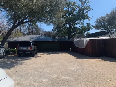
S 10° 00' 00" W 150.00' " 12 7 - ' 5 2 " 6 - ' 2 12'-0" 5'-0" 2 ' - 3 " X 2 5 ' - 3 " 5'-3" 14'-3" 2 ' - 0 " X 3 ' - 0 " 3 ' - 6 " 1 0 ' - 2 " 1 ' - 9 " X 2 6 ' - 0 " 5') 7 1 = T A L P ( @ 1 ' - 9 " 5 ' - 3 " 10'-11 2" 3'-0" 6'-41 " 2 X ' 0 . 3 3.0' 9 ' . 9 3.0' 6.0' X 16.8' " 12 4 - ' 5 2 18'-7" E N I L T O L I L A N G R O I 13.0' ' 0 ' 0 . 5 1 2 ' - 3 " 1 3 ' - 6 " 17'-91 2" 12'-9" 30.0' 19.6' ' 0 . 3 9.0' 24.6' ' 7 . 4 2 X ' 0 . 12.5' 3 ' 5.9' 6 . 0 27.0' X 9.0'' 0 . 0 1 18.0' X 110 102 ' 5 . 6 3.0' X ' 7 . 7 5 X X X 3.0' 6.0' I E N L 9.0' T O L X I L A N G R O I 13.0' ' 0 . 2 2 ' . 0 0 0 7 1 E " 0 0 ' 0 0 ° 0 8 S N 10° 00' 00" E 110.00' (ASSUMED REF. BEARING) 1 SITE PLAN SCALE: 3/32" = 1'-0" e c n e d i s e R s l o h c E T E E R T S I F F L C 1 0 9 1 5 0 7 8 7 X T , N I T S U A NOT PUBLISHED. ALL RIGHTS RESERVED BY MICHAEL T. LANDRUM, INC. DRAWINGS AND SPECIFICATIONS ARE INSTRUMENTS OF SERVICE AND SHALL REMAIN THE PROPERTY OF MIICHAEL T. LANDRUM, INC, ISSUED TO DESCRIBED DESIGN INTENT. THEY ARE NOT TO BE USED ON OTHER PROJECTS OR EXTENTIONS TO THIS PROJECT EXCEPT BY AGREEMENT IN WRITING AND WITH APPROPRIATE COMPENSATION TO TO MICHAEL T. LANDRUM, INC. CONTRACTOR, SUB-CONTRACTORS & SUPPLIERS ARE RESPONSIBLE FOR CONFIRMING AND CORRELATING DIMENSIONS AND CONDITIONS AT JOB SITE, AND SHALL BE RESPONSIBLE FOR ALL LABOR & MATERIALS REQUIRED IN ACCORDANCE WITH DESIGN INTENT. MICHAEL T. LANDRUM, INC. WILL NOT BE RESPONSIBLE FOR CONSTRUCTION MEANS, METHODS, TECHNIQUES, SEQUENCES OR PROCEDURES, OR FOR SAFETY PRECAUTIONS AND PROGRAMS ALL WORK SHALL BE PERFORMED IN ACCORDANCE WITH ALL APPLICABLE CODES AND ORDINANCES. IN CONNECTION WITH THIS PROJECT. TREE LIST 102 - LIVE OAK (22") 110 - MAGNOLIA (23") TREE PROTECTION NOTES: TREE PROTECTION FENCING (5-FOOT CHAIN-LINK FENCE) SHOULD BE EXTENDED TO THE FULL AVAILABLE CRITICAL ROOF ZONE (CRZ) OF ALL PROTECTED TREES (19 INCHES OR GREATER IN DIAMETER). ANY CRITICAL ROOF ZONE AND IS NOT PROTECTED BY FENCING. INSTALL TRUNK WRAP (2x4 LUMBER) WHENEVER PROTECTIVE FENCING IS 5 FEET OR LESS FROM THE TRUNK OF THE TREE. TREE PROTECTION FENCING MUST BE CONTINUOUS AND CREATE A CLOSED, INACCESSIBLE AREA OF ROOT ZONE PROTECTION. TRUNK WRAP WILL BE USE TO PROTECT THE TREE IF FENCING IS 5' OR LESS FROM THE TRUNK OF THE TREE. LOT SIZE: 23,054.87 S.F. IMPERVIOUS COVERAGE CALCULATIONS: EXISTING S.F. NEW/ADDED S.F. 1ST FLOOR CONDITIONED AREA 2,242 S.F. ATTACHED COVERED PARKING 521 S.F. COVERED WOOD DECK (COUNTED AT 100%) COVERED PATIO OTHER - FIREPLACE 328 S.F. 10.3 S.F. 1,808 S.F. TOTAL S.F. 4,050 S.F. 284.5 S.F. 284.5 S.F. 12.5 S.F. 22.8 S.F. TOTAL BUILDING AREA (TBA) 3101.3 S.F. 2,105 S.F. 5,206.3 S.F. TOTAL BUILDING COVERAGE (TBC) 3101.3 S.F. 2,105 S.F. 5,206.3 S.F. DRIVEWAY SIDEWALKS UNCOVERED PATIO UNCOVERED WOOD DECKS (COUNTED AT 50%) AC PADS AND OTHER CONCRETE FLATWORK OTHER (POOL COPING, RETAINING WALLS) 1,548 S.F. 91 S.F. 1,907 S.F. 841.5 S.F. 9 S.F. 165 S.F. 9 S.F. 841.5 S.F. 18 S.F. 165 S.F. TOTAL SITE IMPERVIOUS COVERAGE 6,821.3 S.F. 2,955.5 S.F. 9,776.8 S.F. TOTAL COVERAGE (42.4%) 9,776.8 S.F. ALLOWABLE COVERAGE (45%) 10,374.7 S.F. LEGAL DESCRIPTION: BEING LOTS 10, 11, AND THE SOUTH 40' OF LOT 12, BLOCK 3, CARRINGTON SUBDIVISION OF OUT-LOTS NO. 26, 27, 28, DIVISION D, A SUBDIVISION IN TRAVIS COUNTY, TEXAS, ACCORDING TO THE MAP OR PLAT THEREOF RECORDED IN VOLUME 1, PAGE 94, PLAT RECORDS, TRAVIS COUNTY, TEXAS. Owners ANDREW ECHOLS 1901 Cliff Street Austin Texas 78705 Contractor Monte Goertz Company 3401 Barranca Circle Austin, TX 78731 (512) 423-9312 Monte @Monte Goertzco.com . C N I , M U R D N A L . T L E A H C I M T E E R T S S S O R L U S 2 0 5 1 6 0 0 7 7 S A X E T , N O T S U O H - 5 0 6 4 3 2 6 3 1 7 - i m o c . c n m u r d n a l t l e a h c m @ l e a h c m i i REVISIONS 03.24.25 04.02.25 04.08.25 04.10.25 04.15.25 06.09.25 08.01.25 08.04.25 09.17.25 11.24.25 01.06.26 02.16.26 02.23.26 ISSUED FOR REVIEW ISSUED FOR REVIEW ISSUED FOR REVIEW ISSUED FOR REVIEW ISSUED FOR REVIEW ISSUED FOR REVIEW ISSUED FOR REVIEW ISSUED FOR REVIEW ISSUED FOR REVIEW ISSUED FOR REVIEW ISSUED FOR REVIEW ISSUED FOR REVIEW ISSUED FOR PERMIT DATE: 02.23.26 SHEET DESCRIPTION: ARCHITECTURAL DRAWING ARCHITECTURAL DRAWING SITE PLAN SITE PLAN SCALE: 3/32"=1'-0" SCALE: 3/32"=1'-0" SHEET NUMBER: A A 0.01 0.01 Copyright Michael T. Landrum, Inc. 2013 WM S 10° 00' 00" W 150.00' " 12 7 - ' 5 2 " 6 - ' 2 12'-0" 5'-0" 2 ' - 3 " X 2 5 ' - 3 " 5'-3" 14'-3" 2 ' - 0 " X 3 ' - 0 " 3 ' - 6 " 1 0 ' - 2 " 1 ' - 9 " X 2 6 ' - 0 " 5') 7 1 = T A L P ( @ 1 ' - 9 " 5 ' - 3 " 10'-11 2" 3'-0" 6'-41 " 2 X ' 0 . 3 3.0' 9 ' . 9 3.0' 6.0' X 16.8' " 12 4 - ' 5 2 18'-7" E N I L T O L I L A N G R O I 13.0' ' 0 ' 0 . 5 1 2 ' - 3 " 1 3 ' - 6 " 17'-91 2" 12'-9" 30.0' 19.6' ' 0 . 3 9.0' 24.6' ' 7 . 4 2 X ' 0 . 12.5' 3 ' 5.9' 6 . 0 27.0' X 9.0'' 0 . 0 1 18.0' X 110 102 ' 5 . 6 3.0' X ' 7 . 7 5 X X X 3.0' 6.0' I E N L 9.0' T O L X I L A N G R O I 13.0' ' 0 . 2 2 ' . 0 0 0 7 1 E " 0 0 ' 0 0 ° 0 8 S N 10° 00' 00" E 110.00' (ASSUMED REF. BEARING) 1 SITE PLAN SCALE: 3/32" = 1'-0" e c n e d i s e R s l o h c E T E E R T S I F F L C 1 0 9 1 5 0 7 8 7 X T , N I T S U A NOT PUBLISHED. ALL RIGHTS RESERVED BY MICHAEL T. LANDRUM, INC. DRAWINGS AND SPECIFICATIONS ARE INSTRUMENTS OF SERVICE AND SHALL REMAIN THE PROPERTY OF MIICHAEL T. LANDRUM, INC, ISSUED TO DESCRIBED DESIGN INTENT. THEY ARE NOT TO BE USED ON OTHER PROJECTS OR EXTENTIONS TO THIS PROJECT EXCEPT BY AGREEMENT IN WRITING AND WITH APPROPRIATE COMPENSATION TO TO MICHAEL T. LANDRUM, INC. CONTRACTOR, SUB-CONTRACTORS & SUPPLIERS ARE RESPONSIBLE FOR CONFIRMING AND CORRELATING DIMENSIONS AND CONDITIONS AT JOB SITE, AND SHALL BE RESPONSIBLE FOR ALL LABOR & MATERIALS REQUIRED IN ACCORDANCE WITH DESIGN INTENT. MICHAEL T. LANDRUM, INC. WILL NOT BE RESPONSIBLE FOR CONSTRUCTION MEANS, METHODS, TECHNIQUES, SEQUENCES OR PROCEDURES, OR FOR SAFETY PRECAUTIONS AND PROGRAMS ALL WORK SHALL BE PERFORMED IN ACCORDANCE WITH ALL APPLICABLE CODES AND ORDINANCES. IN CONNECTION WITH THIS PROJECT. TREE LIST 102 - LIVE OAK (22") 110 - MAGNOLIA (23") TREE PROTECTION NOTES: TREE PROTECTION FENCING (5-FOOT CHAIN-LINK FENCE) SHOULD BE EXTENDED TO THE FULL AVAILABLE CRITICAL ROOF ZONE (CRZ) OF ALL PROTECTED TREES (19 INCHES OR GREATER IN DIAMETER). ANY CRITICAL ROOF ZONE AND IS NOT PROTECTED BY FENCING. INSTALL TRUNK WRAP (2x4 LUMBER) WHENEVER PROTECTIVE FENCING IS 5 FEET OR LESS FROM THE TRUNK OF THE TREE. TREE PROTECTION FENCING MUST BE CONTINUOUS AND CREATE A CLOSED, INACCESSIBLE AREA OF ROOT ZONE PROTECTION. TRUNK WRAP WILL BE USE TO PROTECT THE TREE IF FENCING IS 5' OR LESS FROM THE TRUNK OF THE TREE. LOT SIZE: 23,054.87 S.F. IMPERVIOUS COVERAGE CALCULATIONS: EXISTING S.F. NEW/ADDED S.F. 1ST FLOOR CONDITIONED AREA 2,242 S.F. ATTACHED COVERED PARKING 521 S.F. COVERED WOOD DECK (COUNTED AT 100%) COVERED PATIO OTHER - FIREPLACE 328 S.F. 10.3 S.F. 1,808 S.F. TOTAL S.F. 4,050 S.F. 284.5 S.F. 284.5 S.F. 12.5 S.F. 22.8 S.F. TOTAL BUILDING AREA (TBA) 3101.3 S.F. 2,105 S.F. 5,206.3 S.F. TOTAL BUILDING COVERAGE (TBC) 3101.3 S.F. 2,105 S.F. 5,206.3 S.F. DRIVEWAY SIDEWALKS UNCOVERED PATIO UNCOVERED WOOD DECKS (COUNTED AT 50%) AC PADS AND OTHER CONCRETE FLATWORK OTHER (POOL COPING, RETAINING WALLS) 1,548 S.F. 91 S.F. 1,907 S.F. 841.5 S.F. 9 S.F. 165 S.F. 9 S.F. 841.5 S.F. 18 S.F. 165 S.F. TOTAL SITE IMPERVIOUS COVERAGE 6,821.3 S.F. 2,955.5 S.F. 9,776.8 S.F. TOTAL COVERAGE (42.4%) 9,776.8 S.F. ALLOWABLE COVERAGE (45%) 10,374.7 S.F. LEGAL DESCRIPTION: BEING LOTS 10, 11, AND THE SOUTH 40' OF LOT 12, BLOCK 3, CARRINGTON SUBDIVISION OF OUT-LOTS NO. 26, 27, 28, DIVISION D, A SUBDIVISION IN TRAVIS COUNTY, TEXAS, ACCORDING TO THE MAP OR PLAT THEREOF RECORDED IN VOLUME 1, PAGE 94, PLAT RECORDS, TRAVIS COUNTY, TEXAS. Owners ANDREW ECHOLS 1901 Cliff Street Austin Texas 78705 Contractor Monte Goertz Company 3401 Barranca Circle Austin, TX 78731 (512) 423-9312 Monte @Monte Goertzco.com . C N I , M U R D N A L . T L E A H C I M T E E R T S S S O R L U S 2 0 5 1 6 0 0 7 7 S A X E T , N O T S U O H - 5 0 6 4 3 2 6 3 1 7 - i m o c . c n m u r d n a l t l e a h c m @ l e a h c m i i REVISIONS 03.24.25 04.02.25 04.08.25 04.10.25 04.15.25 06.09.25 08.01.25 08.04.25 09.17.25 11.24.25 01.06.26 02.16.26 02.23.26 ISSUED FOR REVIEW ISSUED FOR REVIEW ISSUED FOR REVIEW ISSUED FOR REVIEW ISSUED FOR REVIEW ISSUED FOR REVIEW ISSUED FOR REVIEW ISSUED FOR REVIEW ISSUED FOR REVIEW ISSUED FOR REVIEW ISSUED FOR REVIEW ISSUED FOR REVIEW ISSUED FOR PERMIT DATE: 02.23.26 SHEET DESCRIPTION: ARCHITECTURAL DRAWING ARCHITECTURAL DRAWING SITE PLAN SITE PLAN SCALE: 3/32"=1'-0" SCALE: 3/32"=1'-0" SHEET NUMBER: A A 0.01 0.01 Copyright Michael T. Landrum, Inc. 2013 e c n e d i s e R s l o h c E T E E R T S I F F L C 1 0 9 1 5 0 7 8 7 X T , N I T S U A NOT PUBLISHED. ALL RIGHTS RESERVED BY MICHAEL T. LANDRUM, INC. DRAWINGS AND SPECIFICATIONS ARE INSTRUMENTS OF SERVICE AND SHALL REMAIN THE PROPERTY OF MIICHAEL T. LANDRUM, INC, ISSUED TO DESCRIBED DESIGN INTENT. THEY ARE NOT TO BE USED ON OTHER PROJECTS OR EXTENTIONS TO THIS PROJECT EXCEPT BY AGREEMENT IN WRITING AND WITH APPROPRIATE COMPENSATION TO TO MICHAEL T. LANDRUM, INC. CONTRACTOR, SUB-CONTRACTORS & SUPPLIERS ARE RESPONSIBLE FOR CONFIRMING AND CORRELATING DIMENSIONS AND CONDITIONS AT JOB SITE, AND SHALL BE RESPONSIBLE FOR ALL LABOR & MATERIALS REQUIRED IN ACCORDANCE WITH DESIGN INTENT. MICHAEL T. LANDRUM, INC. WILL NOT BE RESPONSIBLE FOR CONSTRUCTION MEANS, METHODS, TECHNIQUES, SEQUENCES OR PROCEDURES, OR FOR SAFETY PRECAUTIONS AND PROGRAMS ALL WORK SHALL BE PERFORMED IN ACCORDANCE WITH ALL APPLICABLE CODES AND ORDINANCES. IN CONNECTION WITH THIS PROJECT. S 10° 00' 00" W 150.00' " 12 7 - ' 5 2 " 12 4 - ' 5 2 18'-7" E N I L T O L I L A N G R O I " 6 - ' 2 12'-0" 5'-0" 2 ' - 3 " X 2 5 ' - 3 " 5'-3" 14'-3" 2 ' - 0 " X 3 ' - 0 " 3 ' - 6 " 1 0 ' - 2 " 1 ' - 9 " X 2 6 ' - 0 " @ 1 ' - 9 " 5 ' - 3 " 10'-11 2" 3'-0" 6'-41 " 2 X ' 0 . 3 3.0' 9 ' . 9 3.0' 6.0' X 16.8' 13.0' ' 0 ' 0 . 5 1 2 ' - 3 " 1 3 ' - 6 " 17'-91 2" 12'-9" 30.0' X 6.0' 9.0'' 0 . 0 1 18.0' X 110 3.0' ' 5 . 6 3.0' X 19.6' ' 0 . 3 9.0' 24.6' ' 7 . 4 2 X ' 0 . 12.5' 3 ' 5.9' 6 . 0 27.0' X 1/4 CRZ 1/2 CRZ 5') 7 1 = T A L P ( ' . 0 0 0 7 1 E " 0 0 ' 0 0 ° 0 8 S 8" NATURAL WOOD MULCH 1/4 CRZ 102 1/2 CRZ TREE LIST 102 - LIVE OAK (22") 110 - MAGNOLIA (23") TREE PROTECTION NOTES: TREE PROTECTION FENCING (5-FOOT CHAIN-LINK FENCE) SHOULD BE EXTENDED TO THE FULL AVAILABLE CRITICAL ROOF ZONE (CRZ) OF ALL PROTECTED TREES (19 INCHES OR GREATER IN DIAMETER). ANY CRITICAL ROOF ZONE AND IS NOT PROTECTED BY FENCING. INSTALL TRUNK WRAP (2x4 LUMBER) WHENEVER PROTECTIVE FENCING IS 5 FEET OR LESS FROM THE TRUNK OF THE TREE. TREE PROTECTION FENCING MUST BE CONTINUOUS AND CREATE A CLOSED, INACCESSIBLE AREA OF ROOT ZONE PROTECTION. 9.0' I E N L T O L X TRUNK WRAP WILL BE USE TO PROTECT THE TREE IF FENCING IS 5' OR LESS FROM THE TRUNK OF THE TREE. . C N I , M U R D N A L . T L E A H C I M T E E R T S S S O R L U S 2 0 5 1 6 0 0 7 7 S A X E T , N O T S U O H - 5 0 6 4 3 2 6 3 1 7 - i m o c . c n m u r d n a l t l e a h c m @ l e a h c m i i ' 7 . 7 5 X 5' TALL CHAIN-LINK TREE PROTECTION FENCING @ FULL CRZ X I L A N G R O I 13.0' ' 0 . 2 2 N 10° 00' 00" E 110.00' (ASSUMED REF. BEARING) 1 TREE PRESERVATION SCALE: 3/32" = 1'-0" LEGAL DESCRIPTION: BEING LOTS 10, 11, AND THE SOUTH 40' OF LOT 12, BLOCK 3, CARRINGTON SUBDIVISION OF OUT-LOTS NO. 26, 27, 28, DIVISION D, A SUBDIVISION IN TRAVIS COUNTY, TEXAS, ACCORDING TO THE MAP OR PLAT THEREOF RECORDED IN VOLUME 1, PAGE 94, PLAT RECORDS, TRAVIS COUNTY, TEXAS. Owners ANDREW ECHOLS 1901 Cliff Street Austin Texas 78705 Contractor Monte Goertz Company 3401 Barranca Circle Austin, TX 78731 (512) 423-9312 Monte @Monte Goertzco.com REVISIONS 03.24.25 04.02.25 04.08.25 04.10.25 04.15.25 06.09.25 08.01.25 08.04.25 09.17.25 11.24.25 01.06.26 02.16.26 02.23.26 ISSUED FOR REVIEW ISSUED FOR REVIEW ISSUED FOR REVIEW ISSUED FOR REVIEW ISSUED FOR REVIEW ISSUED FOR REVIEW ISSUED FOR REVIEW ISSUED FOR REVIEW ISSUED FOR REVIEW ISSUED FOR REVIEW ISSUED FOR REVIEW ISSUED FOR REVIEW ISSUED FOR PERMIT DATE: 02.23.26 SHEET DESCRIPTION: ARCHITECTURAL DRAWING ARCHITECTURAL DRAWING TREE PRESERVATION SCALE: 3/32"=1'-0" SCALE: 3/32"=1'-0" SHEET NUMBER: A 0.02 A Copyright Michael T. Landrum, Inc. 2013 29'-91 2" 28'-91 " 2 LIVING DECK FIRE PIT LIVING LIVING 1'-0" " 0 - ' 3 BEDROOM 2 BATH 2 ATTIC ACCESS 18x18 2'-71 2" 2'-61 2" 4'-6" 4'-6" O P Q 2'-61 2" PRIVATE GALLERY (NEW CONSTRUCTION) NOTE: DEMO EXIST EXTERIOR WALL SECTION- NEW CONSTRUCTION BEYOND DASHED LINE GALLERY 2'-4" 1'-3" " 8 - ' 1 2'-61 " 2 2'-61 " 2 BAR " 3 - ' 0 1 BEDROOM 1 15'-01 2" 5'-0" 15'-111 2" " 12 2 - ' 5 1 " 0 - ' 4 1 " 0 - ' 3 " 0 - ' 3 COVERED PAVILION BUILT-IN BANQUETTE " 0 - ' 9 5'-0" 3'-6" DINING DINING KITCHEN DECK 42" ISOKERN FIREPLACE 9'-11 " 2 GARDEN INFILL PANTRY ATTIC ACCESS 18x18 KITCHEN KITCHEN ANNEX WINE REFRIG A/C UNIT 3'-4" POWDER FRZR DRWRS REF. " 8 - ' 6 " 1 - ' 7 " 0 - ' 3 " 9 - ' 2 " 12 1 1 - ' 3 " 12 3 " 8 - ' 3 " 12 3 31 " 2 " 12 1 1 - ' 3 " 9 - ' 2 10'-71 2" 31 2" " 12 3 DRESSING ROOM BATH 1 ENTRANCE COURT SERVICE COURT TOOLS " 9 - ' 3 3 " 8 - ' 4 1 GARAGE BEDROOM 3 ATTIC ACCESS 18x18 CLOSET 3 BATH 3 " 1 - ' 1 " 6 - ' 2 " 6 - ' 2 " 4 - ' 6 " 6 - ' 2 " 7 - ' 3 " 0 1 - ' 1 1 " 6 - ' 8 1 " 8 - ' 3 3 " 8 - ' 8 7 4" DIAM. PIPE COLUMNS W/ STEEL PIPE PERGOLA ABOVE W/ POLYGAL ROOFING 2'-5" 5'-8" 29'-9" 29'-2" 13'-0" 5'-8" 2'-6" N R E K O S I " 6 3 E C A L P E R F I 31 2" 2'-4" " 0 - ' 5 " 12 3 FAMILY TERRACE NOTE: TERRACE FF ELEVATION TO MATCH ADJACENT WOOD DECK @ POOL SURROUND 12'-3" 12'-3" " 1 - WALL MOUNT TV ' 1 101 M 1'-4" 2'-0" " 0 - ' 5 HIPPED CEILING @ FAMILY ROOM 24'-6" 1 0 . 3 A / 1 0 " 4 - ' 6 FAMILY ROOM NOTE; RECESS SLAB AT FIREBOX TO SET FLUSH WITH ADJACENT F.F. (TYP) " 1 - ' 1 8'-10" " 0 - ' 5 " 0 - ' 2 " 0 - ' 0 1 1 0 . 3 A / 2 0 L 2'-4" " 0 - ' 5 6'-3" " 1 - ' 1 5'-4" 3'-4" 4'-4" 4'-0" " 0 - ' 4 2'-4" 5'-11" 106 MECH 1 105 POWDER 103 104 " 3 - ' 6 03/A3.01 31 " 2 REF DRWRS 3'-7" 3'-7" ICE C 114 " 4 - ' 4 " 2 - ' 4 " 2 - ' 4 " 9 - ' 1 " 6 - ' 3 1 31 2" 9'-0" " 9 - ' 1 SAUNA " 4 - ' 2 D W DW 5'-4" 7'-8" " 1 - ' 4 1 " 0 1 - ' 7 109 108 J 04/A3.01 LAUNDRY ROOM LAUNDRY ROOM 06/A3.01 1 0 . 3 A / 5 0 " 0 1 - ' 2 13'-7" WINE REFRIG " 0 - ' 3 3'-6" 7" 116 " 12 2 - ' 5 D E PRIMARY BEDROOM (HIP CEILING) 16'-0" 7'-4" 3'-0" 1 0 . 3 A / 7 1 " 2 - ' 2 " 3 - ' 2 " 2 - ' 2 " 12 2 - ' 5 7'-4" 2'-6" 1'-8" 115 " 4 - ' 2 " 12 3 G " 4 - ' 4 LINEN LINEN " 4 - ' 6 11/A3.01 " 4 - ' 6 111 110 " 4 - ' 6 3'-0" 07/A3.01 6'-41 2" 15/A3.01 5'-1" 3'-8" 8'-0" 4'-2" 4'-4" 1'-4" 1'-4" " 8 - ' 4 1 " 12 4 - ' 0 1 PRIMARY BATH 13/A3.01 112 12/A3.01 " 4 - ' 8 14/A3.01 " 4 - ' 8 5'-0" SHOWER 1'-4" PRIMARY CLOSET 1 0 . 3 A / 6 1 1 0 . 3 A / 0 1 15/A3.01 08/A3.01 1 0 . 3 A / 6 1 1 0 . 3 A / 9 0 " 0 - ' 6 " 4 - ' 2 " 4 - ' 8 MECH 2 113 " 12 3 31 2" F " 12 3 31 " 2 3'-8" 4'-0" 9'-0" 1'-8" 4'-6" 37'-31 " 2 14'-51 " 2 1 ADDITION FLOOR PLAN SCALE: 3/16" = 1'-0" 1814 SF e c n e d i s e R s l o h c E T E E R T S I F F L C 1 0 9 1 5 0 7 8 7 X T , N I T S U A NOT PUBLISHED. ALL RIGHTS RESERVED BY MICHAEL T. LANDRUM, INC. DRAWINGS AND SPECIFICATIONS ARE INSTRUMENTS OF SERVICE AND SHALL REMAIN THE PROPERTY OF MIICHAEL T. LANDRUM, INC, ISSUED TO DESCRIBED DESIGN INTENT. THEY ARE NOT TO BE USED ON OTHER PROJECTS OR EXTENTIONS TO THIS PROJECT EXCEPT BY AGREEMENT IN WRITING AND WITH APPROPRIATE COMPENSATION TO TO MICHAEL T. LANDRUM, INC. CONTRACTOR, SUB-CONTRACTORS & SUPPLIERS ARE RESPONSIBLE FOR CONFIRMING AND CORRELATING DIMENSIONS AND CONDITIONS AT JOB SITE, AND SHALL BE RESPONSIBLE FOR ALL LABOR & MATERIALS REQUIRED IN ACCORDANCE WITH DESIGN INTENT. MICHAEL T. LANDRUM, INC. WILL NOT BE RESPONSIBLE FOR CONSTRUCTION MEANS, METHODS, TECHNIQUES, SEQUENCES OR PROCEDURES, OR FOR SAFETY PRECAUTIONS AND PROGRAMS ALL WORK SHALL BE PERFORMED IN ACCORDANCE WITH ALL APPLICABLE CODES AND ORDINANCES. IN CONNECTION WITH THIS PROJECT. . C N I , M U R D N A L . T L E A H C I M T E E R T S S S O R L U S 2 0 5 1 6 0 0 7 7 S A X E T , N O T S U O H - 5 0 6 4 3 2 6 3 1 7 - i m o c . c n m u r d n a l t l e a h c m @ l e a h c m i i REVISIONS 03.24.25 04.02.25 04.08.25 04.10.25 04.15.25 06.09.25 08.01.25 08.04.25 09.17.25 11.24.25 01.06.26 02.16.26 02.23.26 ISSUED FOR REVIEW ISSUED FOR REVIEW ISSUED FOR REVIEW ISSUED FOR REVIEW ISSUED FOR REVIEW ISSUED FOR REVIEW ISSUED FOR REVIEW ISSUED FOR REVIEW ISSUED FOR REVIEW ISSUED FOR REVIEW ISSUED FOR REVIEW ISSUED FOR REVIEW ISSUED FOR PERMIT DATE: 02.23.26 SHEET DESCRIPTION: ARCHITECTURAL DRAWING ARCHITECTURAL DRAWING FLOOR PLAN FLOOR PLAN SCALE: 3/16"=1'-0" SCALE: 3/16"=1'-0" SHEET NUMBER: A A 1.01 1.01 Copyright Michael T. Landrum, Inc. 2013 12 3 WESTERN STATES METAL BOARD AND BATTEN SIDING TO MATCH WIDTH OF EXISTING WOOD BOARD & BATTEN Q P O 3'-11 2" STANDING SEAM ROOFING (TYP) STANDING SEAM COPPER CLADDING @ CHIMNEYS (TYP) PROFILE OF HIPPED CEILING @ FAMILY ROOM NOTE: WRAP FASCIA IN BREAK METAL AND CLAD OVERHANG SOFFIT IN STANDING SEAM TO MATCH STANDING SEAM METAL ROOF 1" DIAM STEEL PURLINS @ 6" O.C. DOUBLE 3" DIAM. STEEL PIPE BEAM " 5 - ' 4 1 " 0 - ' 2 1 101 22'-21 2" " 12 2 - ' 7 1 " 1 1 - ' 8 3'-10" 4" DIAM. STEEL PIPE COLUMN NOTE: BEVELED FINISH CONCRETE BASE/ GRADE BEAM DETAIL TO MATCH EXIST (TYP) I Y F R E V 1 ADDITION ELEVATION - SOUTH SCALE: 1/4" = 1'-0" e c n e d i s e R s l o h c E T E E R T S I F F L C 1 0 9 1 5 0 7 8 7 X T , N I T S U A NOT PUBLISHED. ALL RIGHTS RESERVED BY MICHAEL T. LANDRUM, INC. DRAWINGS AND SPECIFICATIONS ARE INSTRUMENTS OF SERVICE AND SHALL REMAIN THE PROPERTY OF MIICHAEL T. LANDRUM, INC, ISSUED TO DESCRIBED DESIGN INTENT. THEY ARE NOT TO BE USED ON OTHER PROJECTS OR EXTENTIONS TO THIS PROJECT EXCEPT BY AGREEMENT IN WRITING AND WITH APPROPRIATE COMPENSATION TO TO MICHAEL T. LANDRUM, INC. CONTRACTOR, SUB-CONTRACTORS & SUPPLIERS ARE RESPONSIBLE FOR CONFIRMING AND CORRELATING DIMENSIONS AND CONDITIONS AT JOB SITE, AND SHALL BE RESPONSIBLE FOR ALL LABOR & MATERIALS REQUIRED IN ACCORDANCE WITH DESIGN INTENT. MICHAEL T. LANDRUM, INC. WILL NOT BE RESPONSIBLE FOR CONSTRUCTION MEANS, METHODS, TECHNIQUES, SEQUENCES OR PROCEDURES, OR FOR SAFETY PRECAUTIONS AND PROGRAMS ALL WORK SHALL BE PERFORMED IN ACCORDANCE WITH ALL APPLICABLE CODES AND ORDINANCES. IN CONNECTION WITH THIS PROJECT. 1" DIAM STEEL PURLINS @ 6" O.C. PROFILE OF HIPPED CEILING @ FAMILY ROOM 12 3 DOUBLE 3" DIAM. STEEL PIPE BEAM 4" DIAM. STEEL PIPE COLUMN " 3 - ' 4 1 " 0 - ' 2 1 " 1 1 - ' 8 10" M L 106 J D E G NOTE: WRAP FASCIA IN BREAK METAL AND CLAD OVERHANG SOFFIT IN STANDING SEAM TO MATCH STANDING SEAM METAL ROOF WESTERN STATES METAL BOARD AND BATTEN SIDING TO MATCH WIDTH OF EXISTING WOOD BOARD & BATTEN " 0 - ' 0 1 2 ADDITION ELEVATION - EAST SCALE: 1/4" = 1'-0" 12 3 PROFILE OF HIPPED CEILING @ FAMILY ROOM NOTE: WRAP FASCIA IN BREAK METAL AND CLAD OVERHANG SOFFIT IN STANDING SEAM TO MATCH STANDING SEAM METAL ROOF . C N I , M U R D N A L . T L E A H C I M T E E R T S S S O R L U S 2 0 5 1 6 0 0 7 7 S A X E T , N O T S U O H - 5 0 6 4 3 2 6 3 1 7 - i m o c . c n m u r d n a l t l e a h c m @ l e a h c m i i F 3 113 " 0 - ' 0 1 " 0 - ' 0 1 115 116 114 OPEN TO FAMILY ROOM " 0 - ' 2 1 ADDITION ELEVATION - NORTH SCALE: 1/4" = 1'-0" WESTERN STATES METAL BOARD AND BATTEN SIDING TO MATCH WIDTH OF EXISTING WOOD BOARD & BATTEN 4 ADDITION ELEVATION - WEST SCALE: 1/4" = 1'-0" GENERAL NOTE: VERIFY FINISH OF METAL SIDING, SOFFIT & ROOF WITH OWNER AND ARCHITECT. " 1 1 - ' 8 REVISIONS 03.24.25 04.02.25 04.08.25 04.10.25 04.15.25 06.09.25 08.01.25 08.04.25 09.17.25 11.24.25 01.06.26 02.16.26 02.23.26 ISSUED FOR REVIEW ISSUED FOR REVIEW ISSUED FOR REVIEW ISSUED FOR REVIEW ISSUED FOR REVIEW ISSUED FOR REVIEW ISSUED FOR REVIEW ISSUED FOR REVIEW ISSUED FOR REVIEW ISSUED FOR REVIEW ISSUED FOR REVIEW ISSUED FOR REVIEW ISSUED FOR PERMIT DATE: 02.23.26 SHEET DESCRIPTION: ARCHITECTURAL DRAWING ARCHITECTURAL DRAWING EXTERIOR ELEVATION EXTERIOR ELEVATION SCALE: 1/4"=1'-0" SCALE: 1/4"=1'-0" SHEET NUMBER: A A 2.01 2.01 Copyright Michael T. Landrum, Inc. 2013 " 0 - ' 0 1 STANDING SEAM COPPER CLADDING @ CHIMNEYS (TYP) STANDING SEAM ROOFING (TYP) NOTE: WRAP FASCIA IN BREAK METAL AND CLAD OVERHANG SOFFIT IN STANDING SEAM TO MATCH STANDING SEAM METAL ROOF WESTERN STATES METAL BOARD AND BATTEN SIDING TO MATCH WIDTH OF EXISTING WOOD BOARD & BATTEN 12 3 NOTE: WRAP FASCIA IN BREAK METAL AND CLAD OVERHANG SOFFIT IN STANDING SEAM TO MATCH STANDING SEAM METAL ROOF OPEN TO FAMILY ROOM 5 ADDITION COURTYARD ELEVATION - NORTH SCALE: 1/4" = 1'-0" 6 ADDITION COURTYARD ELEVATION - SOUTH SCALE: 1/4" = 1'-0" GENERAL NOTE: VERIFY FINISH OF METAL SIDING, SOFFIT & ROOF WITH OWNER AND ARCHITECT. HIP CEILING DETAIL PERIMETER LIGHT COVE DETAIL " 3 3" " 7 - ' 4 1 " 0 - ' 2 1 " 0 - ' 8 OPEN TO HALL K I I T H G N L E C G N I T S X E O I GALLERY OPEN TO EXISTING HOUSE T H C T A M 23'-6" 3'-0" 7 SECTION @ FAMILY ROOM SCALE: 1/4" = 1'-0" e c n e d i s e R s l o h c E T E E R T S I F F L C 1 0 9 1 5 0 7 8 7 X T , N I T S U A NOT PUBLISHED. ALL RIGHTS RESERVED BY MICHAEL T. LANDRUM, INC. DRAWINGS AND SPECIFICATIONS ARE INSTRUMENTS OF SERVICE AND SHALL REMAIN THE PROPERTY OF MIICHAEL T. LANDRUM, INC, ISSUED TO DESCRIBED DESIGN INTENT. THEY ARE NOT TO BE USED ON OTHER PROJECTS OR EXTENTIONS TO THIS PROJECT EXCEPT BY AGREEMENT IN WRITING AND WITH APPROPRIATE COMPENSATION TO TO MICHAEL T. LANDRUM, INC. CONTRACTOR, SUB-CONTRACTORS & SUPPLIERS ARE RESPONSIBLE FOR CONFIRMING AND CORRELATING DIMENSIONS AND CONDITIONS AT JOB SITE, AND SHALL BE RESPONSIBLE FOR ALL LABOR & MATERIALS REQUIRED IN ACCORDANCE WITH DESIGN INTENT. MICHAEL T. LANDRUM, INC. WILL NOT BE RESPONSIBLE FOR CONSTRUCTION MEANS, METHODS, TECHNIQUES, SEQUENCES OR PROCEDURES, OR FOR SAFETY PRECAUTIONS AND PROGRAMS ALL WORK SHALL BE PERFORMED IN ACCORDANCE WITH ALL APPLICABLE CODES AND ORDINANCES. IN CONNECTION WITH THIS PROJECT. . C N I , M U R D N A L . T L E A H C I M T E E R T S S S O R L U S 2 0 5 1 6 0 0 7 7 S A X E T , N O T S U O H - 5 0 6 4 3 2 6 3 1 7 - i m o c . c n m u r d n a l t l e a h c m @ l e a h c m i i REVISIONS 03.24.25 04.02.25 04.08.25 04.10.25 04.15.25 06.09.25 08.01.25 08.04.25 09.17.25 11.24.25 01.06.26 02.16.26 02.23.26 ISSUED FOR REVIEW ISSUED FOR REVIEW ISSUED FOR REVIEW ISSUED FOR REVIEW ISSUED FOR REVIEW ISSUED FOR REVIEW ISSUED FOR REVIEW ISSUED FOR REVIEW ISSUED FOR REVIEW ISSUED FOR REVIEW ISSUED FOR REVIEW ISSUED FOR REVIEW ISSUED FOR PERMIT DATE: 02.23.26 SHEET DESCRIPTION: ARCHITECTURAL DRAWING ARCHITECTURAL DRAWING EXTERIOR ELEVATION EXTERIOR ELEVATION SCALE: 1/4"=1'-0" SCALE: 1/4"=1'-0" SHEET NUMBER: A A 2.02 2.02 Copyright Michael T. Landrum, Inc. 2013 3" " 3 3" " 7 - ' 4 1 " 0 - ' 2 1 LIGHT TROUGH/COVE @ PERIMETER OF FAMILY ROOM LIGHT TROUGH/COVE @ PERIMETER OF FAMILY ROOM L M " 7 - ' 4 1 WING WALL & HEADER @ 34" DP. COUNTER FULL HT MIRRORED SPLASH FLOATING WOOD SHELVING VERIFY SURROUND W/ OWNER MASONRY FIREBOX " 0 - ' 8 OPEN TO ENTRY GALLERY " 0 - ' 8 REF DRWRS ICE " 0 - ' 2 " 0 - ' 8 " 4 LIGHTING @ FURR DN FULL HT MIRROR " 6 - ' 4 " 0 - ' 3 MIRRORED WALL BELOW " 0 - ' 5 " 0 - ' 2 " 0 - ' 3 TO SAUNA FULL HT TILE SPLASH WASHER/DRYER UNDERCOUNTER " 0 - ' 5 " 0 - ' 2 " 0 - ' 3 J DW 8" 5'-0" 6'-4" 5'-0" 8" 8" 5'-0" 2'-0" 10'-0" 4'-0" 3'-4" 2'-0" 2'-0" 5'-7" 2'-10" 01 FAMILY ROOM - EAST SCALE: 3/8" = 1'-0" 02 FAMILY ROOM - WEST SCALE: 3/8" = 1'-0" 03 POWDER ROOM - NORTH SCALE: 3/8" = 1'-0" 04 LAUNDRY ROOM - SOUTH SCALE: 3/8" = 1'-0" 05 LAUNDRY ROOM - EAST SCALE: 3/8" = 1'-0" e c n e d i s e R s l o h c E T E E R T S I F F L C 1 0 9 1 5 0 7 8 7 X T , N I T S U A NOT PUBLISHED. ALL RIGHTS RESERVED BY MICHAEL T. LANDRUM, INC. DRAWINGS AND SPECIFICATIONS ARE INSTRUMENTS OF SERVICE AND SHALL REMAIN THE PROPERTY OF MIICHAEL T. LANDRUM, INC, ISSUED TO DESCRIBED DESIGN INTENT. THEY ARE NOT TO BE USED ON OTHER PROJECTS OR EXTENTIONS TO THIS PROJECT EXCEPT BY AGREEMENT IN WRITING AND WITH APPROPRIATE COMPENSATION TO TO MICHAEL T. LANDRUM, INC. CONTRACTOR, SUB-CONTRACTORS & SUPPLIERS ARE RESPONSIBLE FOR CONFIRMING AND CORRELATING DIMENSIONS AND CONDITIONS AT JOB SITE, AND SHALL BE RESPONSIBLE FOR ALL LABOR & MATERIALS REQUIRED IN ACCORDANCE WITH DESIGN INTENT. MICHAEL T. LANDRUM, INC. WILL NOT BE RESPONSIBLE FOR CONSTRUCTION MEANS, METHODS, TECHNIQUES, SEQUENCES OR PROCEDURES, OR FOR SAFETY PRECAUTIONS AND PROGRAMS ALL WORK SHALL BE PERFORMED IN ACCORDANCE WITH ALL APPLICABLE CODES AND ORDINANCES. IN CONNECTION WITH THIS PROJECT. OPEN ADJUS SHELVING OPEN ADJUS SHELVING OPEN ADJUS SHELVING OPEN ADJUS SHELVING OPEN ADJUS SHELVING OPEN ADJUS SHELVING OPEN ADJUS SHELVING OPEN ADJUS SHELVING OPEN ADJUS SHELVING 2R2S 2R2S 2R2S 2R2S 1R1S 1R1S OPEN ADJUS SHELVING " 0 - ' 0 1 2R2S 2R2S 2R2S " 0 - ' 5 " 0 - ' 2 " 0 - ' 3 " 6 - ' 5 OPEN ADJUS SHELVING OPEN ADJUS SHELVING " 6 - ' 4 4'-10" 4" 2" 9'-71 2'-0" 2'-0" 2" 12'-11 6'-0" 2'-0" 10'-0" 2'-0" 07 PRIMARY CLOSET - SOUTH SCALE: 3/8" = 1'-0" 08 PRIMARY CLOSET - NORTH SCALE: 3/8" = 1'-0" 09 PRIMARY CLOSET - EAST SCALE: 3/8" = 1'-0" 10 PRIMARY CLOSET - WEST SCALE: 3/8" = 1'-0" WINE REFRIG FULL HT TILE SPLASH 2'-10" 2" 7'-91 2'-0" 06 LAUNDRY ROOM - NORTH SCALE: 3/8" = 1'-0" LIGHTING @ FURR DN FULL HT MIRROR MIRRORED WALL BELOW " 0 - ' 0 1 " 6 - ' 5 " 6 - ' 4 " 6 - ' 5 " 6 - ' 1 " 0 - ' 3 MIRRORED SPLASH 3'-4" 8'-0" 3'-10" 3'-0" 3'-0" FRAMELESS FULL HT GLASS SHOWER ENCLOSURE FULL HT TILE @ TUB/SHOWER WALLS F 1'-4" " 4 " 6 " 6 - ' 1 4'-10" " 0 - ' 3 8'-2" 6'-4" 4'-0" " 14 2 - ' 2 " 3 " 0 - ' 0 1 " 0 - ' 3 116 115 VERIFY SURROUND W/ OWNER MASONRY FIREBOX 17'-0" 11 PRIMARY BATH - SOUTH SCALE: 3/8" = 1'-0" 12 PRIMARY TOILET - N SCALE: 3/8" = 1'-0" 13 PRIMARY TOILET - S SCALE: 3/8" = 1'-0" 14 PRIMARY BATH - NORTH SCALE: 3/8" = 1'-0" 15 CLOSET ISLAND - N/S SCALE: 3/8" = 1'-0" 16 CLOSET ISLAND - E/W SCALE: 3/8" = 1'-0" 17 PRIMARY BEDROOM - WEST SCALE: 3/8" = 1'-0" " 3 - ' 6 " 0 - ' 2 " 0 - ' 5 " 0 - ' 3 . C N I , M U R D N A L . T L E A H C I M T E E R T S S S O R L U S 2 0 5 1 6 0 0 7 7 S A X E T , N O T S U O H - 5 0 6 4 3 2 6 3 1 7 - i m o c . c n m u r d n a l t l e a h c m @ l e a h c m i i REVISIONS 03.24.25 04.02.25 04.08.25 04.10.25 04.15.25 06.09.25 08.01.25 08.04.25 09.17.25 11.24.25 01.06.26 02.16.26 02.23.26 ISSUED FOR REVIEW ISSUED FOR REVIEW ISSUED FOR REVIEW ISSUED FOR REVIEW ISSUED FOR REVIEW ISSUED FOR REVIEW ISSUED FOR REVIEW ISSUED FOR REVIEW ISSUED FOR REVIEW ISSUED FOR REVIEW ISSUED FOR REVIEW ISSUED FOR REVIEW ISSUED FOR PERMIT DATE: 02.23.26 SHEET DESCRIPTION: ARCHITECTURAL DRAWING ARCHITECTURAL DRAWING INTERIOR ELEVATION SCALE: 3/8"=1'-0" SHEET NUMBER: A 3.01 A Copyright Michael T. Landrum, Inc. 2013 WINDOW SCHEDULE - ECHOLS RESIDENCE (NEW ADDITION) NOTES: SILL HT. FRAME GLAZING REMARKS 1. VERIFY SCHEDULE WITH DOOR SWINGS ON PLAN WINDOW FRAME SIZE RE: DETAILS FOR R.O. NO. TYPE 2. ALL INTERIOR DOOR ARE 8'-0" TALL, SOLID CORE, SLAB FLAT PANEL, WOOD PAINTED, 1-3/4" THICK W/ RABBITED WOOD JAMBS/FRAMES. ALL INTERIOR DOOR JAMBS TO BE KURFED TO ALLOW FOR SQUARE SHEETROCK RETURNS ON BOTH SIDES; EXTERIOR DOOR & WINDOW JAMBS TO RECEIVE SHEETROCK RETURNS @ INTERIOR WALLS, STEEL PLATE RETURNS @ EXTERIOR WALLS. 3. UNLESS OTHERWISE NOTED, ALL EXTERIOR DOOR & WINDOW UNITS TO BE WOOD FRAME (STAINED) CYPRESS TO MATCH EXISTING, INSULATED GLASS, (VERIFY W/ ARCHITECT & OWNER) W H MAT'L FINISH THK. TYPE D E F G J L M O P Q 1 1 3 1 4 5 5 1 1 1 2'-6" 2'-6" 8'-0" 4'-0" 8'-0" 8'-0" 5'-4" 8'-0" 0'-0" 0'-0" 2'-8" 0'-0" WOOD STAINED WOOD STAINED WOOD STAINED WOOD STAINED 7'-8" 2'-0" 3'-0" WOOD STAINED 5'-0" 5'-0" 3'-6" 3'-6" 3'-6" 12'-0" 12'-0" 6'-11" 6'-11" 6'-11" 0'-0" 0'-0" 0'-0" 0'-0" 0'-0" WOOD STAINED WOOD STAINED WOOD STAINED WOOD STAINED WOOD STAINED 1/4" 1/4" 1/4" 1/4" 1/4" 1/4" 1/4" 1/4" 1/4" 1/4" INSULATED TEMPERED INSULATED TEMPERED INSULATED TEMPERED INSULATED TEMPERED FIXED FIXED FIXED FIXED INSULATED TEMPERED FIXED INSULATED TEMPERED INSULATED TEMPERED FIXED FIXED INSULATED TEMPERED INSULATED TEMPERED INSULATED TEMPERED FIXED FIXED FIXED RE: SCHEDULE RE: SCHEDULE O P Q D E G FINISH FLOOR E L U D E H C S : E R F F E L U D E H C S : E R E H C S : E R TYPE 1 TYPE 2 TYPE 3 RE: SCHEDULE " 8 - ' 3 " 4 " 0 - ' 8 E L U D E H C S : E R RE: SCHEDULE J FINISH FLOOR L M E H C S : E R E H C S : E R TYPE 4 TYPE 5 TYPE 6 DOOR SCHEDULE - ECHOLS RESIDENCE (NEW ADDITION) DOOR FRAME NO. DOOR SIZE W H THK. TYPE MAT'L FINISH MAT'L FINISH WOOD STAINED WOOD STAINED H S E R H T S S A L G E P Y T INSULATED TEMPERED . . E W D H O N T E S REMARKS EXTERIOR DOOR; (3) E.Q. PANELS; FIX/SL/FIX; WITH TRANSOM ABOVE 101 12'-0" 8'-0" 1-3/4" 103 104 105 106 108 109 110 111 112 113 114 115 116 4'-0" 2'-8" 2'-8" 2'-8" 2'-8" 3'-0" 3'-0" 3'-0" 2'-8" 2'-8" 12'-6" 4'-6" 4'-6" 8'-0" 8'-0" 8'-0" 8'-0" 8'-0" 8'-0" 8'-0" 8'-0" 8'-0" 8'-0" 8'-0" 8'-0" 8'-0" 1-3/4" 1-3/4" 1-3/4" 1-3/4" 1-3/4" 1-3/4" 1-3/4" 1-3/4" 1-3/4" 1-3/4" 1-3/4" 1-3/4" 1-3/4" D B A A C A A A A A C E F F WOOD STAINED WOOD STAINED SOLID CORE; POCKET DOOR WOOD STAINED WOOD STAINED WOOD STAINED WOOD STAINED WOOD STAINED WOOD STAINED WOOD STAINED WOOD STAINED WOOD STAINED WOOD STAINED WOOD STAINED WOOD STAINED WOOD STAINED WOOD STAINED WOOD STAINED WOOD STAINED WOOD STAINED WOOD STAINED WOOD STAINED WOOD STAINED WOOD STAINED WOOD STAINED WOOD STAINED WOOD STAINED SOLID CORE SOLID CORE EXTERIOR DOOR; CLAD TO MATCH EXTERIOR FINISH SOLID CORE SOLID CORE SOLID CORE SOLID CORE SOLID CORE INSULATED TEMPERED INSULATED TEMPERED INSULATED TEMPERED EXTERIOR DOOR; CLAD TO MATCH EXTERIOR FINISH EXTERIOR DOOR; (4) E.Q. PANELS; FIX/SL/SL/FIX EXTERIOR DOOR EXTERIOR DOOR RE: SCHEDULE RE: SCHEDULE RE: SCHEDULE RE: SCHEDULE 103 E L U D E H C S : E R 106 113 E L U D E H C S : E R 101 E L U D E H C S : E R 104 110 105 111 112 108 109 FINISH FLOOR TYPE A TYPE B TYPE C TYPE D " 8 - ' 3 " 4 " 0 - ' 8 E L U D E H C S : E R RE: SCHEDULE RE: SCHEDULE 114 115 116 E L U D E H C S : E R E L U D E H C S : E R FINISH FLOOR TYPE E TYPE F e c n e d i s e R s l o h c E T E E R T S I F F L C 1 0 9 1 5 0 7 8 7 X T , N I T S U A NOT PUBLISHED. ALL RIGHTS RESERVED BY MICHAEL T. LANDRUM, INC. DRAWINGS AND SPECIFICATIONS ARE INSTRUMENTS OF SERVICE AND SHALL REMAIN THE PROPERTY OF MIICHAEL T. LANDRUM, INC, ISSUED TO DESCRIBED DESIGN INTENT. THEY ARE NOT TO BE USED ON OTHER PROJECTS OR EXTENTIONS TO THIS PROJECT EXCEPT BY AGREEMENT IN WRITING AND WITH APPROPRIATE COMPENSATION TO TO MICHAEL T. LANDRUM, INC. CONTRACTOR, SUB-CONTRACTORS & SUPPLIERS ARE RESPONSIBLE FOR CONFIRMING AND CORRELATING DIMENSIONS AND CONDITIONS AT JOB SITE, AND SHALL BE RESPONSIBLE FOR ALL LABOR & MATERIALS REQUIRED IN ACCORDANCE WITH DESIGN INTENT. MICHAEL T. LANDRUM, INC. WILL NOT BE RESPONSIBLE FOR CONSTRUCTION MEANS, METHODS, TECHNIQUES, SEQUENCES OR PROCEDURES, OR FOR SAFETY PRECAUTIONS AND PROGRAMS ALL WORK SHALL BE PERFORMED IN ACCORDANCE WITH ALL APPLICABLE CODES AND ORDINANCES. IN CONNECTION WITH THIS PROJECT. . C N I , M U R D N A L . T L E A H C I M T E E R T S S S O R L U S 2 0 5 1 6 0 0 7 7 S A X E T , N O T S U O H - 5 0 6 4 3 2 6 3 1 7 - i m o c . c n m u r d n a l t l e a h c m @ l e a h c m i i 1 WINDOW SCHEDULE SCALE: 1/4" = 1'-0" 2 DOOR SCHEDULE SCALE: 1/4" = 1'-0" REVISIONS 03.24.25 04.02.25 04.08.25 04.10.25 04.15.25 06.09.25 08.01.25 08.04.25 09.17.25 11.24.25 01.06.26 02.16.26 02.23.26 ISSUED FOR REVIEW ISSUED FOR REVIEW ISSUED FOR REVIEW ISSUED FOR REVIEW ISSUED FOR REVIEW ISSUED FOR REVIEW ISSUED FOR REVIEW ISSUED FOR REVIEW ISSUED FOR REVIEW ISSUED FOR REVIEW ISSUED FOR REVIEW ISSUED FOR REVIEW ISSUED FOR PERMIT DATE: 02.23.26 SHEET DESCRIPTION: ARCHITECTURAL DRAWING ARCHITECTURAL DRAWING ARCHITECTURAL DRAWING ARCHITECTURAL DRAWING WINDOW & DOOR SCHEDULE WINDOW & DOOR SCHEDULE SCALE: 1/4"=1'-0" SCALE: 1/4"=1'-0" SCALE: 1/4"=1'-0" SCALE: 1/4"=1'-0" SHEET NUMBER: A4.01 A4.01 Copyright Michael T. Landrum, Inc. 2013 RAFTERS FINISH AS SCHEDULED UNLESS INDICATED OTHERWISE LINTEL OVER ALL WINDOWS & DOORS TO BE (2)2x4S ABOVE (2) 2x91 4" MEMBERS FASCIA VARIES 2x4 HEAD STANDING SEAM METAL ROOF 15# ROOFING FELT OVER SHARKSKIN ULTRA SA C.D.X. PLYWOOD KOOLPLY DECKING RE: STRUCT. DWGS. 3" DIA LEADER & DOWNSPOUT 2x4 @ 16" O.C. COPPER SCREEN GUTTER 4"x55 3 8" 2x4 METAL SOFFIT ZIPSYSTEM 7 16" WALL SHEATHING SHARKSKIN ULTRA SA WATER RESISTANT BARRIER WESTERN STATES BOARD & BATTEN METAL SIDING (12" BOARD COVERAGE) 2x4 STUD (VERIFY W/ARCH.) TYPICAL WINDOW/ DOOR HEADER DETAIL SCALE: 1" = 1'-0" 1 TYPICAL WINDOW SILL ZIPSYSTEM 7 16" WALL SHEATHING SHARKSKIN ULTRA SA WATER RESISTANT BARRIER WESTERN STATES BOARD & BATTEN METAL SIDING (12" BOARD COVERAGE) 2x4 STUD (VERIFY W/ARCH.) 8" TALL EXPOSED & FINISHED CONCRETE BASE " 8 CONCRETE F.F. " 4 " 34 6" 2" 31 COR-A-VENT SV-5 4.5 WEEP FROM TEKTRIM INSECT SCREENING EXPOSED LEDGE DETAIL (SLOPE TO DRAIN) NOTE: PARGED SAND TEXTURE @ EXPOSED FACE OF GRADE BEAM TYPICAL WINDOW SECTION DETAIL SCALE: 1" = 1'-0" 2 e c n e d i s e R s l o h c E T E E R T S I F F L C 1 0 9 1 5 0 7 8 7 X T , N I T S U A NOT PUBLISHED. ALL RIGHTS RESERVED BY MICHAEL T. LANDRUM, INC. DRAWINGS AND SPECIFICATIONS ARE INSTRUMENTS OF SERVICE AND SHALL REMAIN THE PROPERTY OF MIICHAEL T. LANDRUM, INC, ISSUED TO DESCRIBED DESIGN INTENT. THEY ARE NOT TO BE USED ON OTHER PROJECTS OR EXTENTIONS TO THIS PROJECT EXCEPT BY AGREEMENT IN WRITING AND WITH APPROPRIATE COMPENSATION TO TO MICHAEL T. LANDRUM, INC. CONTRACTOR, SUB-CONTRACTORS & SUPPLIERS ARE RESPONSIBLE FOR CONFIRMING AND CORRELATING DIMENSIONS AND CONDITIONS AT JOB SITE, AND SHALL BE RESPONSIBLE FOR ALL LABOR & MATERIALS REQUIRED IN ACCORDANCE WITH DESIGN INTENT. MICHAEL T. LANDRUM, INC. WILL NOT BE RESPONSIBLE FOR CONSTRUCTION MEANS, METHODS, TECHNIQUES, SEQUENCES OR PROCEDURES, OR FOR SAFETY PRECAUTIONS AND PROGRAMS ALL WORK SHALL BE PERFORMED IN ACCORDANCE WITH ALL APPLICABLE CODES AND ORDINANCES. IN CONNECTION WITH THIS PROJECT. . C N I , M U R D N A L . T L E A H C I M T E E R T S S S O R L U S 2 0 5 1 6 0 0 7 7 S A X E T , N O T S U O H - 5 0 6 4 3 2 6 3 1 7 - i m o c . c n m u r d n a l t l e a h c m @ l e a h c m i i REVISIONS 03.24.25 04.02.25 04.08.25 04.10.25 04.15.25 06.09.25 08.01.25 08.04.25 09.17.25 11.24.25 01.06.26 02.16.26 02.23.26 ISSUED FOR REVIEW ISSUED FOR REVIEW ISSUED FOR REVIEW ISSUED FOR REVIEW ISSUED FOR REVIEW ISSUED FOR REVIEW ISSUED FOR REVIEW ISSUED FOR REVIEW ISSUED FOR REVIEW ISSUED FOR REVIEW ISSUED FOR REVIEW ISSUED FOR REVIEW ISSUED FOR PERMIT DATE: 02.23.26 SHEET DESCRIPTION: ARCHITECTURAL DRAWING ARCHITECTURAL DRAWING ARCHITECTURAL DRAWING ARCHITECTURAL DRAWING TYPICAL WALL DETAIL SCALE: 1"=1'-0" SHEET NUMBER: A5.01 A Copyright Michael T. Landrum, Inc. 2013 SYMBOL DESCRIPTION WATT/VOLT/LAMP LOCATION REMARKS 4" LOW VOLTAGE RECESSED 50W/12V/MR16 SP THRU-OUT REMARKS A1 A2 A3 A4 B CM1 CM3 DOWNLIGHT/ PINHOLE TRIM/ INTEGRAL TRANSFORMER/ 4" LOW VOLTAGE RECESSED DOWNLIGHT/ READING TRIM/ INTEGRAL TRANSFORMER/ 3" LOW VOLTAGE RECESSED DOWNLIGHT/ BAFFLE TRIM/ INTEGRAL TRANSFORMER/ 4" LOW VOLTAGE RECESSED DOWNLIGHT/ ADJUST. TRIM/ INTEGRAL TRANSFORMER/ 3" TRIMLESS WALL WASHERS (SQUARE OPENING) THRU-OUT REMARKS 50W/12V/MR16 FL/ THRU-OUT REMARKS 50W/12V/MR16 FL/ THRU-OUT REMARKS THRU-OUT REMARKS 52" INTERIOR CEILING FAN/ 250W/120V/NA THRU-OUT REMARKS 10" DIA FROSTED GLASS DOMED 60W/120V/A-19 HAL THRU-OUT REMARKS FIXTURE/ SINGLE LAMP/ 14" DIA FROSTED GLASS DOMED 60W/120V/A-19 HAL THRU-OUT REMARKS FIXTURE/ DOUBLE LAMP/ NUTONE BATH EXHAUST FAN VENT, HEAT, LIGHT AND NIGHT LIGHT 250W/ NO LAMP THRU-OUT REMARKS PENDANT FIXTURE/ OWNER SELECTED DECORATIVE WALL SCONCE/ OWNER SELECTED LOW VOLTAGE CYLINDER TRACK HEAD/ INTEGRAL TRANSFORMER/ SINGLE CIRCUIT TRACK/ TYPICAL FOR ALL LENGTHS 300W/120V/VARIES THRU-OUT REMARKS 250W/120V/VARIES THRU-OUT REMARKS 50W/12V/MR16 NSP THRU-OUT REMARKS NOT APPLICABLE THRU-OUT REMARKS 1' X 4' FLUORESCENT THRU-OUT REMARKS WALL WASH RECESSED STEP LIGHTS NOT APPLICABLE THRU-OUT REMARKS CEILING MOUTED FIXTURE/ OWNER SELECTED THRU-OUT REMARKS SYMBOL DESCRIPTION WATT/VOLT/LAMP LOCATION REMARKS UC 2 UC3 MP GFI TV SD CO S XENON/ UNDER CABINET 20W/12V/2XG4 BI-PIN THRU-OUT REMARKS LIGHT/ TWO LAMP XENON/ UNDER CABINET 20W/12V/G4 BI-PIN THRU-OUT REMARKS LIGHT/ THREE LAMP FLOOD LIGHTS NOT APPLICABLE THRU-OUT REMARKS MONOPOINT LIGHT NOT APPLICABLE THRU-OUT REMARKS LIGHT SWITCH NOT APPLICABLE THRU-OUT REMARKS 3-WAY LIGHT SWITCH NOT APPLICABLE THRU-OUT REMARKS RHEOSTAT NOT APPLICABLE THRU-OUT REMARKS DUPLEX OUTLET NOT APPLICABLE THRU-OUT REMARKS DUPLEX OUTLET NOT APPLICABLE THRU-OUT REMARKS DUPLEX OUTLET RECESSED IN FLOOR W/ ANODIZED ALUM. COVER CABLE TELEVISION NOT APPLICABLE THRU-OUT REMARKS NOT APPLICABLE THRU-OUT REMARKS TELEPHONE JACK NOT APPLICABLE THRU-OUT REMARKS SMOKE DETECTOR NOT APPLICABLE THRU-OUT REMARKS CARBON MONOXIDE DETECTOR NOT APPLICABLE THRU-OUT REMARKS CEILING MOUNT SPEAKER NOT APPLICABLE THRU-OUT REMARKS VOLUME CONTROL NOT APPLICABLE THRU-OUT REMARKS CAMERA NOT APPLICABLE THRU-OUT REMARKS 4" DIAM. PIPE COLUMNS W/ STEEL PIPE PERGOLA ABOVE W/ POLYGAL ROOFING FAMILY TERRACE GFI WALL MOUNT TV CONCEALED LED STRIP LIGHTING @ COVE MOULD @ CEILING GFI A3 N R E K O S I " 6 3 E C A L P E R F I A3 A3 GFI LIVING DECK FIRE PIT LIVING LIVING BEDROOM 2 BATH 2 ATTIC ACCESS 18x18 COVERED PAVILION BUILT-IN BANQUETTE DINING DINING KITCHEN DECK 42" ISOKERN FIREPLACE GARDEN INFILL PANTRY ATTIC ACCESS 18x18 MP FAMILY ROOM FP MP MP GFI BAR GFI REF DRWRS ICE POWDER MECH 1 A3 A3 GFI GFI UCL D W SAUNA DW A3 A3 GFI LAUNDRY ROOM LAUNDRY ROOM A3 A3 A3 A3 SD CO GFI UCL GFI WINE REFRIG A3 SD CO CONCEALED LED STRIP LIGHTING @ COVE MOULD @ CEILING GFI PRIMARY BEDROOM (HIP CEILING) A3 PRIVATE GALLERY PRIVATE GALLERY A3 (NEW CONSTRUCTION) TO LTS BEYOND GALLERY KITCHEN KITCHEN ANNEX WINE REFRIG GFI BEDROOM 1 A/C UNIT DRESSING ROOM BATH 1 ENTRANCE COURT SERVICE COURT TOOLS GARAGE GFI A3 GFI A3 A3 A3 A3 A3 A3 A3 A3 GFI A3 A3 A3 GFI PRIMARY BATH A3 A3 A3 A3 MECH 2 PRIMARY CLOSET A3 A3 A3 A3 GFI A3 A3 A3 GFI GFI GFI BEDROOM 3 ATTIC ACCESS 18x18 CLOSET 3 BATH 3 1 ADDITION ELECTRICAL PLAN SCALE: 3/16" = 1'-0" 1814 SF e c n e d i s e R s l o h c E T E E R T S I F F L C 1 0 9 1 5 0 7 8 7 X T , N I T S U A POWDER FRZR DRWRS REF. NOT PUBLISHED. ALL RIGHTS RESERVED BY MICHAEL T. LANDRUM, INC. DRAWINGS AND SPECIFICATIONS ARE INSTRUMENTS OF SERVICE AND SHALL REMAIN THE PROPERTY OF MIICHAEL T. LANDRUM, INC, ISSUED TO DESCRIBED DESIGN INTENT. THEY ARE NOT TO BE USED ON OTHER PROJECTS OR EXTENTIONS TO THIS PROJECT EXCEPT BY AGREEMENT IN WRITING AND WITH APPROPRIATE COMPENSATION TO TO MICHAEL T. LANDRUM, INC. CONTRACTOR, SUB-CONTRACTORS & SUPPLIERS ARE RESPONSIBLE FOR CONFIRMING AND CORRELATING DIMENSIONS AND CONDITIONS AT JOB SITE, AND SHALL BE RESPONSIBLE FOR ALL LABOR & MATERIALS REQUIRED IN ACCORDANCE WITH DESIGN INTENT. MICHAEL T. LANDRUM, INC. WILL NOT BE RESPONSIBLE FOR CONSTRUCTION MEANS, METHODS, TECHNIQUES, SEQUENCES OR PROCEDURES, OR FOR SAFETY PRECAUTIONS AND PROGRAMS ALL WORK SHALL BE PERFORMED IN ACCORDANCE WITH ALL APPLICABLE CODES AND ORDINANCES. IN CONNECTION WITH THIS PROJECT. . C N I , M U R D N A L . T L E A H C I M T E E R T S S S O R L U S 2 0 5 1 6 0 0 7 7 S A X E T , N O T S U O H - 5 0 6 4 3 2 6 3 1 7 - i m o c . c n m u r d n a l t l e a h c m @ l e a h c m i i REVISIONS 03.24.25 04.02.25 04.08.25 04.10.25 04.15.25 06.09.25 08.01.25 08.04.25 09.17.25 11.24.25 01.06.26 02.16.26 02.23.26 ISSUED FOR REVIEW ISSUED FOR REVIEW ISSUED FOR REVIEW ISSUED FOR REVIEW ISSUED FOR REVIEW ISSUED FOR REVIEW ISSUED FOR REVIEW ISSUED FOR REVIEW ISSUED FOR REVIEW ISSUED FOR REVIEW ISSUED FOR REVIEW ISSUED FOR REVIEW ISSUED FOR PERMIT DATE: 02.23.26 SHEET DESCRIPTION: ARCHITECTURAL DRAWING ARCHITECTURAL DRAWING ELECTRICAL PLAN SCALE: 3/16"=1'-0" SCALE: 3/16"=1'-0" SHEET NUMBER: E 1.01 1.01 Copyright Michael T. Landrum, Inc. 2013 WOOD FRAMING: (continued) FLOOR TRUSSES: DRAINAGE, WATERPROOFING AND VENTILATION: REINFORCED CONCRETE: DESIGN DATA Trusses to be designed by truss engineer employed by truss 1. manufacturer and in accordance with - National Design Specification for Wood Construction, AF&PA, National Design Standard for Metal Plate Connected Wood - Truss Construction, ANSI/TPI 1-1995 - Local code jurisdictions Design trusses for the minimum line and point loads shown on 2. plan (line loads from upper walls are minimum 100 lb/ft u.n.o.) and, unless noted otherwise on the plan, the following minimum area loads: The following items are beyond the scope of the structural engineer and are therefore the responsibility of others. The client is responsible for arranging for the design of these systems. Any mention of these items on these drawings is for information purposes only and does not relieve the client of these responsibilities. STANDARD SPECIFICATIONS AND CODES: Structural Concrete Building Code Requirements for Reinforced Concrete, ACI 318-02. Drainage systems including surface drainage, any area inlets, grate drains, french drains and subgrade drain pipes. 1. Waterproofing systems including vapor barriers, roofing, flashing, waterproofing and drip edges. Concrete shall meet the following requirements: 3000 psi C33 1 1/2" 28 day strength: aggregate type: max. aggregate size: MATERIALS: Ventilation systems including crawlspace and attic. 2. Reinforcing steel shall meet the following requirements: - - - NAILING SCHEDULE: joist to sill or girder, toe nail 1"x6" subfloor or less to each joist, face nail 2" subfloor to joist or girder, blind and face nail sole plate to joist or blocking, face nail top or sole plate to stud, end nail stud to sole plate, toe nail 3-8d 2-8d 2-16d 16d @16"o.c. 2-16d 3-8d or 2-16d double studs, face nail 10d @24"o.c. double top plates, face nail sole plate to joist or blocking at braced wall panels double top plates, minimum 48" offset of end joints, face nail in lapped area blocking between joists or rafters to top plate, toe nail rim joist to top plate, toe nail top plates, laps at corners and intersections, face nail built-up header, two pieces with 1/2" spacer continued header, two pieces ceiling joists to plate, toe nail continuous header to stud, toe nail ceiling joist, laps over partitions, face nail ceiling joist to parallel rafters, face nail rafter to plate, toe nail 1" brace to each stud and plate, face nail 1"x6" sheathing to each bearing, face nail 1"x8" sheathing to each bearing, face nail wider than 1"x8" sheathing to each bearing, face nail 10d @24"o.c.. 3-16d @16" o.c. 8-16d 3-8d 8d @ 6"o.c. 2-10d 16d @ 16"o.c. each edge 16d @ 16"o.c. each edge 3-8d 4-8d 3-10d 3-10d 2-16d 2-8d or 2 stpls 1 3/4 2-8d or 2 stpls 1 3/4 3-8d or 3 stpls 1 3/4 3-8d or 4 stpls 1 3/4 built-up corner studs 10d @ 24"o.c. built-up girders and beams, 2" lumber layers, at top and bottom and staggered. Two nails at ends and at each splice. 10d @ 32"o.c. 2" planks roof rafters to ridge, valley or hip rafters: toe nail face nail collar ties to rafters, face nail 2-16d @ ea. bearing 4-16d 3-16d 3-8d 5/16" to 1/2" wood structural panel 6d (wall) 8d (roof) 6" edge 12" field 19/32" to 1" wood structural panel 8d 6" edge 12" field 1-1/8" to 1-1/4" wood structural panel 10d 6" edge 12" field 1/2" gypsum sheathing 4" edge8" field 1-1/2" galv. roofing nail or 1-1/2" screw, type w or s 5/8" gypsum sheathing 4" edge8" field 1-3/4" galv. roofing nail or 1-5/8" screw, type w or s GENERAL: 1. Dimensions refer to rough surfaces. The contractor must verify all dimensions prior to start of construction the engineer shall be notified of any discrepancies or inconsistencies. 2. All drawings are considered part of the contract documents. The contractor shall be responsible for review and coordination of all drawings and specifications prior to the start of construction. Any discrepancies that occur shall be brought to the attention of the engineer prior to the start of construction so that clarification can be issued. Any work in conflict with the contract documents or any code requirements shall be corrected by the contractor at his own expense and at no expense to the owner or structural engineer. 3. These drawings are based on architectural drawings by: Michael T. Landrum, Inc. dated February 16, 2026 All work shall conform to the minimum standards of the building 4. code as well as any other regulating authority over any portion of the work including those additional codes and standards listed in the structural notes and specifications. 5. The engineer shall not control and shall not be responsible for construction means, methods, techniques, sequences or procedures; for safety precautions and programs in connection with the work; for acts or omissions of the contractor, subcontractor or for any persons performing the work; or for the failure of any of them to carry out the work in accordance with the contract documents. Site observations by field representatives of the engineer are 6. solely for the purpose of determining if the work of the contractor is proceeding in accordance with the structural contract drawings. This limited site observation should not be construed as exhaustive or continuous to check the quality or quantity of the work, but rather an effort to guard the owner against defects or deficiencies in the work of the contractor. 7. All structures require periodic maintenance to extend life span and to insure structural integrity from exposure to the environment. A planned program of maintenance shall be established by the building owner. This program shall include items such as painting of structural steel, protective coating for concrete, sealants, caulked joints, expansion joints, control joints, spalls and cracks in concrete. - STRUCTURAL FASTENERS: NAILS: All nails sinker nails per ASTM F1667-95, steel wire, t-head diamond point, round smooth shank, bright. FINISHES: Where a preservative other than borate is used and connectors and fasteners (including nails and bolts) contact treated lumber, use stainless steel connectors and fasteners, unless builder and supplier can demonstrate that pressure treatment is not corrosive to galvanized metal. GLUE: Glue shall meet the requirements of the American Plywood Association adhesive specification AFG-01 and shall be applied as directed by the glue manufacturer. Glue may be applied manually or with pneumatic or electric equipment. EXPANSION ANCHORS: Simpson Strong-Bolt, 1/2" dia., installed as directed by manufacturer. 6. a. WOOD SCREWS, LAG SCREWS AND BOLTS: Wood screws shall comply with ASME B18.6.1. Unless noted otherwise, screws are #8. Lag screws shall comply with ASME B18.2.1. Unless noted otherwise, lag screws are 1/2" dia. by length as required to penetrate secondary member entirely minus 1/2". Applicable ASTM specifications for bolts: For common bolts: For nuts: For washers: For threaded rod: ASTM A307, Gr.A (Fu= 60 ksi) ASTM A563 ASTM F436 ASTM A36 (Fy=36 ksi, Fu = 58-80 ksi) WOOD FRAMING: GENERAL: ROOF AND CEILING STRUCTURE NOTES: Lumber: All materials and workmanship shall conform with the 1. requirements of the latest "National Design Specifications for Stress-Grade Lumber and its Fastenings" by National Forest Products Association. All lumber shall be Southern Pine (S4S) conforming to the 2. standard grading and dressing rules of the Southern Pine Inspection Bureau. Unless indicated otherwise, the minimum grade of structural 3. members shall be as follows: studs : other lumber : no. 3 no. 2 Microlam (LVL) laminated veneer lumber: LVL shall be 4. manufactured by Trus Joist, and design shall be in accordance with ICBO ES ER-4979. Where shown on plan, provide purlin same size as rafters and 1. braced with (2)2x4 braces at 48" o.c.. Slope braces between 45 degrees and vertical and lap onto rafters and nail Ridge board braced as shown on plan with (2) 2x4 braces 2. sloped between 60 degrees and vertical. Brace roof only as shown on plan. Contractor must compare 3. resulting rafter spans to allowable span chart and contact engineer for approval of any necessary additional braces. Unless noted otherwise, for ridges, hips and valleys, use one 4. mill size larger than the common rafters it supports. Center any splices on an approved brace point. At point-of-support for braces, adequately block walls and 5. beams to prevent rotation and horizontal movement. Maximum Ceiling Joist Span Tables: Compare with ceiling joist sizes shown on plan and contact engineer if discrepancies are found. #2 Southern Pine Ceiling Joists: spacing: : 2x6 : 2x8 : 2x10 : 2x12 24" o.c.16" o.c. 12" o.c. 9'-10" 12'-0" 13'-11" 12'-6" 15'-3" 17'-7" 14'-9" 18'-1" 20'-11" 17'-5" 21'-8" 24'-0" #2 Douglas Fir-South Ceiling Joists: spacing: : 2x6 : 2x8 : 2x10 : 2x12 24" o.c.16" o.c. 12" o.c. 10'-4" 12'-8" 14'-1" 13'-1" 16'-0" 18'-6" 16'-0" 19'-7" 22'-7" 18'-6" 22'-8" 24'-0" from International Residential Code Table R802.4(2) with 20 psf live load, 10 psf dead load, L/240 allowable deflection Maximum Rafter Span Tables for rafters with Light Roof Covering and Not Supporting Ceiling: Compare with rafter sizes shown on plan and contact engineer if discrepancies are found. #2 Southern Pine Rafters: spacing: : 2x6 : 2x8 : 2x10 : 2x12 24" o.c.16" o.c. 12" o.c. 11'-0" 13'-6" 15'-7" 13'-11" 17'-1" 19'-8" 16'-6" 20'-3" 23'-5" 19'-6" 23'-10" 24'-0" #2 Douglas Fir-South Rafters: spacing: : 2x6 : 2x8 : 2x10 : 2x12 24" o.c.16" o.c. 12" o.c. 11'-7" 14'-1" 15'-6" 14'-8" 17'-11" 20'-5" 17'-10" 21'-11" 24'-0" 20'-9" 24'-0" 24'-0" from International Residential Code Table R802.5.1(1) with 20 psf live load, 10 psf dead load, L/180 allowable Unless noted otherwise, install Simpson H2.5 hurricane ties at Block beams, joists, rafters and trusses at bearing as required 8. every rafter. 9. to prevent rotation. Plywood or OSB: Sheathing/single floor shall be exterior grade 5. bear the following APA span rating: 6. 15/32" roof sheathing : 1 1/8" single floor t&g : 15/32" wall sheathing : 32/16 48 oc 32/16 All floor sheathing shall be glued to the joists. The field-glued 6. system shall comply with the recommendations of the American Plywood Association. At roofs, unsupported plywood panel end and side edges shall 7. be backed with 2x4 flat blocking or Simpson panel sheathing clips. 8. All framing connectors shall be Simpson Strong-Tie. Where connectors and fasteners contact treated lumber, use stainless steel connectors and fasteners, unless builder and supplier can demonstrate that pressure treatment is not corrosive to galvanized metal. STUD WALL NOTES: 1. See architectural drawings for exact plate height. Compare architect's plate heights and wall sizes to the table 2. below for acceptable maximum. Contact engineer if discrepancies are found. 7. supporting roof only 2x4 @ 24" o.c. 2x4 @ 16" o.c. 2x6 @ 24" o.c. 2x6 @ 16" o.c. 10'-0" 12'-0" 16'-0" 18'-0" supporting one floor and a roof 2x4 @ 24" o.c. not permitted 10'-0" 2x4 @ 16" o.c. 14'-0" 2x6 @ 24" o.c. 18'-0" 2x6 @ 16" o.c. 3. Bottom plate: Treated 2x same width as wall studs. Anchor with 1/2" dia. anchor bolt embedded 7" and spaced maximum 6'-0" o.c.. Locate anchors within 12" of each end of each plate section. Attach interior walls to slab with pafs spaced at 12" o.c. with 4. two pins 6" and 10" from each end of each plate. 5. Where joists, trusses or rafters are spaced more than 16" o.c. and bearing studs below are spaced at 24" members must bear within 5" of studs beneath. Drilling and notching - Studs: In exterior walls or bearing partitions, notch a maximum of 25%. In nonbearing partitions, notch a maximum of 40%. b. c. Any stud, bore/drill no closer than 5/8" to edge of stud and not in the same section as a cut or notch and a maximum diameter of 40%. d. Studs may be bored to 60% of stud width provided the stud is doubled and no more than two successive studs are bored. With engineer's prior approval simpson HSS/SS stud shoes may be used in specific cases of notches or bores exceeding these maximums. 7. Drilling and notching - Top plate: When piping in a wall necessitates the cutting of a top plate by more than 50% its width, use a Simpson RPS strap tie at each plate with six 16d nails each side of notch. POWDER-ACTUATED FASTENERS (PAFS): WALL BRACING NOTES: PAFs shall comply with CABO NER-272. where permitted by details, wood sill plates may be fastened to the concrete slab using powder driven pins following manufacturer's recommendations. The fastening system shall have ICBO approval. Pins shall have a minimum shank diameter of 0.177", a minimum length of 3 1/4", and be spaced per the details. FINISHING MATERIALS: 1. Masonry Veneer: Maximum wall height: Install over a backing of wood wall and a. limited in height to a maximum of 30 feet above the foundation (38 feet permitted at the top of gable ends). b. Masonry on wood: Where indicated on plans, masonry weighing less than 40 psf may be supported on wood framing (deflection limited to L/600). Install a movement joint between the veneer supported by wood and the veneer supported by foundation. Anchorage: Anchor to wood wall framing with c. corrosion-resistant 22 gage x 7/8" corrugated sheet metal ties spaced a maximum of 24" horizontally and 19.5" vertically. Lintels over openings: Support masonry on loose lintels per d. code supported on masonry to foundation at each end. Isolation joints: Install vertical isolation/expansion joints at e. approximately 25 feet on center. 1. Braced wall lines: Using braced wall panel construction in accordance with the prescriptive methods of IRC, brace walls as follows: b. a. Exterior walls: Continuous structural panel sheathing (thickness as noted above), including above and below openings, shall be used on the outside face of all exterior walls (blocking of edges not required), and any braced wall lines that include an exterior wall are considered adequately braced. Interior walls: 1x4 let-in braces sloped between 45 and 60 degrees from horizontal and notched into top and bottom plates and intervening studs and attached with two 8d nails at each plate/stud or simpson WB wall bracing installed in accordance with manuf. specs. or 1/2" thickness gypsum board minimum 48" wide attached to studs w/ 6d nails @ 7" o.c.. Bracing locations: As described below. where 2. architectural layout will not permit the application of these presciptive methods, use engineered shear walls as indicated and detailed on these drawings. Contractor must review drawings prior to construction and contact engineer if discrepancies are found. a. For one story or top story of two or three: Locate at each end and at least every 25 feet on center but not less than 16% of braced wall line. b. First story of two story second story of three story: Locate at each end and at least every 25 feet on center but not less than 25% of braced wall line. HANGER SCHEDULE Member Size Simpson Designation Floor Load Roof Load 2x4 2x6 2x8 2x10 2x12 (2)2x4 (2)2x6 (2)2x8 (2)2x10 (2)2x12 (3)2x6 (3)2x8 (3)2x10 (3)2x12 LU24 LU26 LU28 LU28 LU210 LUS24-2 LUS26-2 LUS28-2 LUS210-2 LUS210-2 LUS26-3 LUS28-3 LUS210-3 LUS210-3 445 665 890 890 555 830 1,110 1,110 1,110 1,390 765 960 1,000 1,250 1,265 1,765 1,585 2,210 1,765 2,210 1,000 1,250 1,265 1,585 1,765 2,210 1,765 2,210 Locate braced wall panels within 12'-6" of the end of each 3. braced wall line. (2)1.75x11.875 HGUS48 6,805 7,925 (2)1.75x14 HGUS410 8,780 8,940 Gypsum: Comply with GA-216-2000 "Application and Finishing 2. of Gypsum Board." Flexibility details in GA-216-2000 such as control joints and corner details shall be used. 4. lines. Out-of-plane offsets up to 4'-0" are permitted in braced wall (2)1.75x16 HGUS410 8,780 8,940 Tile: Comply with American National Standard Specifications 3. for the Installation of Ceramic Tile. Flexibility details in specification such as control and expansion joints shall be used. Alternate braced wall panel: In one and two story houses, a 5. panel constructed in accordance with IRC R602.10.6 can be considered a braced panel. (2)1.75x18 HGUS414 10,015 10,015 (3)1.75x11.875 HGUS5.50/12 9,155 9,155 (3)1.75x14 HGUS5.50/14 10,015 10,015 (3)1.75x16 HGUS5.50/14 10,015 10,015 (3)1.75x18 HGUS5.50/14 10,015 10,015 Top chord live load: Top chord dead load: Bottom chord dead load: Maximum deflections: under live load only: under live + dead load: 40 psf 10 psf 5 psf L/360 L/240 3. Prior to fabrication, truss design drawings bearing the seal and registration number of Texas registered engineer shall be submitted to: Builder/Architect for approval of all truss dimensions, pitches - and elevations; - Engineer for appoval of truss layout and design inputs. 4. Strongbacks: Install continuous 2x6 (min.) strongbacks through floor trusses at mid-span and spaced a maximum of 10'-0" o.c. - Fasten with three 16d nails at each vertical. SELECT FILL : Scarify and re-compact all areas to receive fill. Surfaces 1. steeper than 1 vertical to 4 horizontal which are to receive fill must be benched. 2. Select underslab fill material shall be composed of hard durable particles of gravel or crushed stone and shall meet the following criteria: Gradation: sieve size 1-3/4" 1-1/2" 3/4" No. 4 No. 40 % finer by weight 100 85 - 100 45 - 75 25 - 70 10 - 40 Material passing the no. 40 sieve: % minus no. 40 25-40 10-25 max. PI 15 20 min. PI 3 4 Where vertical web members are not suitably located for - strongback attachment, install vertical 2x4 block fastened with two 16d nails at top and bottom chords. Maximum liquid limit of the minus no. 40 material shall be 45. No organic matter is permitted. - - Restrain strongback at each end. Locate strongback as close to bottom chord as possible. Compaction shall be to 95 percent of maximum laboratory 3. density determined in accordance with ASTM D 698. Material shall be within three percent of optimum moisture at time of compaction. 5. Alterations to trusses: Cutting and altering trusses is not permitted. 6. Bracing: Restrain top chord with floor sheathing and bottom chord with ceiling gypsum. Restrain trusses at points of bearing to prevent toppling. 7. Load transfer through inter-floor space: Use same-size blocking to transfer load from upper walls/columns to lower supporting walls/columns/beams. do not place point loads on unsupported floor sheathing. 8. Transitory floor vibration and sound transmission: The floor system includes no measures to specifically control floor vibration or sound transmission. Expect similar performance to similar systems in similar projects. Contact engineer prior to construction if specific performance criteria are desired. ROOF TRUSSES: Trusses to be designed by truss engineer employed by truss 1. manufacturer and in accordance with National Design Specification for Wood Construction, AF&PA, Placements should be in lifts not exceeding six inches after 4. compaction. 5. Backslopes: Select fill shall extend a minimum of three feet horizontally beyond slab edges before sloping downward at 1V:2H backslope to natural soil. Backslope fill shall be well compacted. If perimeter grade beams are carried into natural soil, backslope fill is not required. REQUIRED TESTING AND APPROVALS · Fill material composition, placement and compaction shall be tested and approved by the Geotechnical Engineer. A 100 pound sample of proposed fill material shall be submitted to the Geotechnical Engineer a minimum 7 days in advance of filling and compaction operations to determine Moisture-Density Relationship. Testing Frequency:Not less than one field density test per 2,000 square feet and minimum 3 tests per lift. · · If foundation bearing elements (including exterior grade beams and interior piers or hard points) penetrate fill, THE ABOVE TESTING AND APPROVALS ARE NOT REQUIRED, and the underslab fill will be considered forming fill. National Design Standard for Metal Plate Connected Wood Truss Construction, ANSI/TPI 1-1995 FILL PLACEMENT: Local code jurisdictions Design roof trusses for the minimum line and point loads 2. shown on plan and, the following minimum area loads, unless noted otherwise on the plan, : Top chord live load: Top chord dead load: Bot. chord live load: Bot. chord dead load: Maximum deflections: under live load only: under live+dead load: 20 psf 10 psf Light roof 20 psf Heavy roof 10 psf 5 psf L/360 L/240 1. Use select fill as specified below (not on site fill) in areas under building footprints. All compaction to minimum of 95% of the maximum dry density obtained from standard proctor (ASTM D 698). No remove and replace required beyond organics and top soil. Scarify and re-compact all areas to receive fill. surfaces 2. steeper than IV:4H which are to receive fill must be benched. 3. Select underslab fill material shall be composed of hard durable particles of gravel or crushed stone and shall meet the following criteria: A. Gradation 3. Prior to fabrication, truss design drawings bearing the seal and registration number of Texas registered engineer shall be submitted to: - - Builder/architect for approval of all truss dimensions, pitches and elevations; B. Engineer for approval of truss layout and design inputs. 4. Strongbacks: install continuous 2x6 (min.) strongbacks through trusses at mid-span and spaced a maximum of 10'-0" o.c. Fasten with three 16d nails at each vertical. sieve size 1-3/4" 1-1/2" 3/4" NO. 4 NO. 40 % finer by wt. 100 85-100 45-75 25-70 10-40 Material passing the no. 40 sieve shall meet the following: % passing no. 40 25-40 10-25 Maximum liquid limit of the -no. 40 material shall be 45. No organic matter is permitted. max. PI 15 20 Where vertical web members are not suitably located for strongback attachment, install vertical 2x4 block fastened with two 16d nails at bottom chords. Placements should be in lifts not exceeding six inches after 4. compaction. A one inch sand level-up course may be placed immediately below concrete slab and waterproof membrane. - - - - - - - Proposed fill material should be submitted to testing agency for 5. approval, in advance of placement. Backslopes: Select fill shall extend a minimum of three feet 6. horizontally before sloping downward at 1V:2H backslope to natural soil. Backslope fill shall be well compacted. If perimeter grade beams are carried into natural soil, backslope fill is not required. Restrain strongback at each end. Locate strongback as close to bottom chord as possible. 5. Alterations to trusses: cutting and altering trusses is not permitted. 6. Truss bracing: - - - - - Restrain top chord with roof sheathing. Brace bottom chord with 1x4 spaced per truss designers requirements (8'-0" maximum). Restrain trusses at points of bearing with blocking and hurricane ties per details. Brace web compression members with continuous 2x4 per truss designers requirements. Install 2x4 X-braces at third points of common truss span. Extend X-braces from girder truss to girder truss. GENERAL BUILDING CODE: The contract documents are based on the requirements of THE 2024 INTERNATIONAL RESIDENTIAL CODE. Ground snow load: Wind speed (3 second gust): Exposure category: Seismic design category: Live Loads: exterior balconies : deck : fire escapes : passenger vehicle garages : attics without storage : attics with storage : rooms other : sleeping rooms : stairs : guardrails and handrails : 5 psf 115 mph C A 60 psf 40 40 50 10 20 40 30 40 200 lbs roof slope 4:12 4:12 to <12:12 12:12 and up tributary area 201- 600 16 14 12 0- 200 20 psf 16 12 601- up 12 12 12 Dead Loads: roofing: metal (2 psf) flooring: ceramic tile 3/4" thick (10 psf) hardwood 7/8" thick (4 psf) carpet and pad (2 psf) Note: Materials indicated above were assumed in design. Prior to construction, builder must compare to actual materials and weights and contact engineer if differences are found. Actual dead loads must not exceed the loads indicated. #3 to #18 bars: 3" Roof Live Load: #3 to #18: ASTM A615 grade 60 REINFORCING STEEL COVERAGE: For layer nearest surface unless specified otherwise on drawings: Concrete surfaces cast against and permanently in contact 1. with earth: 2. Concrete surfaces exposed to earth or weather: #3 to #5 bars: #6 to #18 bars: 1.5" 2" Concrete surfaces not exposed to weather or in contact with 3. earth: #3 to #11 bars in slabs & walls: #3 to #18 bars in beams & columns: 1" 1.5" DETAILS: Contractor shall submit proposed locations for construction 1. joints not shown on drawings for review by the Architect and Structural Engineer. Embedded conduits, pipes, and sleeves shall meet the 2. requirements of ACI 318-02, Section 6.3. CONCRETE CRACK CONTROL: Deflections: 1. Install crack control joints @ 15'-0" o.c.e.w. If crack control is not a consideration as determined by both the builder and the owner, then the joints may be eliminated. Create crack control joints by tooling or sawcutting to a depth 2. of one third the slab thickness. Tool the base of all drops-in-slab to function as control joints. STRUCTURAL STEEL STANDARD SPECIFICATIONS AND CODES: Structural steel design, fabrication and construction governed by ASD Specification for Structural Steel Buildings; Specification for Structural Joints using ASTM A325 or A490 bolts; and Code of Standard Practice for Steel Buildings and Bridges. MATERIAL: The building movement specified below is anticipated and should be considered by the contractor in the performance of the work. rafters : floors/ceilings : others : L/180 L/360 L/240 STRUCTURAL OBSERVATION: 1. The structural engineer of record, or his designate, shall provide structural observation of the structural system for general conformance to the approved plans and specifications at significant construction stages and at completion of the structural system as noted elsewhere in the contract documents. The contractor shall notify the engineer a minimum of 72 hours 2. prior to the date the observation is required. All hot rolled structural steel plates, shapes and bars shall be 1. new steel conforming to ASTM A6-98A. 3. The following items require structural observation: - - Foundation reinforcing and pre-pour setup Framing prior to insulation FOUNDATION: The foundation design is based on the geotechnical investigation performed by HOLT ENGINEERING dated May 17, 2023 (file no.04-10323). Unless noted otherwise on these drawings, structural steel 2. shall be as follows: W-shapes: C-shapes: L-shapes: HSS-shapes: ASTM A992 ASTM A36 ASTM A36 ASTM A500, Fy = 46 KSI All connection material including bearing plates, gusset plates, 3. stiffener plates, angles, etc.: ASTM A36 (unless higher grade is required by strength) CONNECTIONS: 1. See typical details on drawings. STRUCTURAL BOLTS AND THREADED FASTENERS: Unless noted otherwise, all bolts in structural connections shall 1. conform to ASTM A325 type 1. 2. 3. Threaded rod: F 1554 grade 36 Pins: ASTM A36 WELDING min. PI 3 4 Welding shall conform to the American Welding Society 1. Standard D1.1. Unless noted otherwise, electrodes for welding shall conform 2. to E70XX (SMAW) ANCHOR RODS 1. Anchor rods: ASTM F1554 grade 36 2. Adhesive anchors shall have been tested and qualified for use in accordance with ICC-ES AC308 for cracked and uncracked concrete recognition. Pre-approved adhesive anchors include: - Hilti HIT-HY 200 A/R V3 (ICC-ES ESR-4868) GROUT Grout: non-metallic, non-shrink grout with a minimum strength 1. of 6000 psi. HEADED CONCRETE ANCHORS: Headed concrete anchors shall be nelson headed concrete 1. anchors (or approved equal), and shall conform to ASTM A108, grades C-1010 through C-1020. Anchors shall be automatically end welded with suitable stud 2. welding equipment in the shop or in the field. welding shall be in accordance with the recommendations of the nelson stud welding company. i . g n i r e e n g n E y f f u D f o i n o s s m r e p i n e t t i r w s s e r p x e e h t i i g n n a t b o t s r i f t u o h t i w , y t r a p d r i h t a o t d e n g s s a i r o , r e n n a m y n a n i i d e p o c r o d e g n a h c , d e c u d o r p e r e b t o n y a m d n a g n i r e e n g n E y f f i u D f o y t r e p o r p e r a i s g n w a r d e s e h T Austin, Texas (512) 402-0074 Firm Registration No. F-8637 26 feb 2026 PROJECT NUMBER: 23020.03 CLIENT: Andrew Echols n o i t i d d A e c n e d s e R s o h c E l i t e e r t S f f i l C 1 0 9 1 s a x e T , n i t s u A ISSUE: package 0 - for permit 1 - for construction date 29 oct 2025 26 feb 2026 SHEET TITLE: Notes SHEET NUMBER: S1.0 9" 2'-6" 25'-3" 2'-3" 13'-9 1/2" 44'-6 1/2" 0 . 3 S p 1 1p S3.0 2a S3.0 2a S3.0 1p S3.0 " 4 / 3 5 - ' 3 " 2 / 1 0 - ' 5 " 4 / 3 5 - ' 3 " 1 - ' 6 " 1 1 - ' 6 " 1 - ' 6 " 2 / 1 6 - ' 9 " 2 / 1 6 - ' 9 " 0 - ' 1 1 " 5 - ' 9 7 " 1 - ' 3 3 " 2 / 1 0 - ' 1 1 " 4 / 1 0 - ' 1 1 1p S3.0 1p S3.0 2'-6" 1p S3.0 2'-3" 1a S3.0 1'-0" 1a S3.0 2t S3.0 x . 3 S a 2 0 . 3 S a 2 1a S3.0 0 . 3 S a 1 1'-0" 8'-2 1/2" 9'-2 1/2" 1a S3.0 0 . 3 S a 2 0 . 3 S a 2 0 . 3 S a 2 Remove a minimum 12" of existing soil and replace with a minimum of 12" of select underslab fill 9'-0" 0 . 3 S a 1 1a S3.0 . 0 3 S a 2 0 . 3 S a 1 1e S3.0 0 . 3 S a 1 0 . 3 S e 1 1a S3.0 0 . 3 S a 1 3'-3" 4'-9 1/2" 9'-0" 17'-0 1/2" 2t S3.0 1a S3.0 2'-6" 0 . 3 S a 1 0 . 3 S a 1 2'-6" 1a S3.0 10'-7 1/2" 0 . 3 S a 1 " 0 - ' 2 1 " 9 " 2 / 1 7 - ' 5 " 0 - ' 2 1 " 2 / 1 7 " 5 - ' 9 7 " 0 1 - ' 2 2 " 3 - ' 4 " 1 - ' 6 " 3 - ' 5 1 " 3 - ' 5 1 2a S3.0 2a S3.0 0 . 3 S a 1 9'-6" 8'-7 1/2" 8'-7 1/2" 11'-1 1/2" 37'-10 1/2" 44'-3 1/2" 1a S3.0 6'-5" Foundation Plan 1/4" = 1'-0" Full Size; 1/8" = 1'-0" Half Size PLAN NOTES: plan north 1. 2. 3. See S1.0 for notes. Unless noted otherwise, slabs are 5" thick concrete slab-on-ground reinforced w/ #4 @ 16" o.c.e.w. Hard Point: where the depth of underslab fill exceeds 48" inches (measured from bottom of slab at interior beam intersections) install 12" dia. concrete piers (formed or drilled) through the underslab fill and reinforced with (4) #4 vertical (extend 12" into beam) and #3 ties @ 18" o.c. S2.0 i . g n i r e e n g n E y f f u D f o i n o s s m r e p i n e t t i r w s s e r p x e e h t i i g n n a t b o t s r i f t u o h t i w , y t r a p d r i h t a o t d e n g s s a i r o , r e n n a m y n a n i i d e p o c r o d e g n a h c , d e c u d o r p e r e b t o n y a m d n a g n i r e e n g n E y f f i u D f o y t r e p o r p e r a i s g n w a r d e s e h T Austin, Texas (512) 402-0074 Firm Registration No. F-8637 26 feb 2026 PROJECT NUMBER: 23020.03 CLIENT: Andrew Echols n o i t i d d A e c n e d s e R s o h c E l i t e e r t S f f i l C 1 0 9 1 s a x e T , n i t s u A ISSUE: package 0 - for permit 1 - for construction date 29 oct 2025 26 feb 2026 SHEET TITLE: Foundation Plan SHEET NUMBER: S2.0 HSS 4.25 column per 4a S3.0 HSS 4.25 column per 4a S3.0 2 - 3" dia. standard pipe beams HSS 4.25 column per 4a S3.0 HSS 4.25 column per 4a S3.0 s m a e b e p p i d r a d n a t s . a d i " 3 - 2 s m a e b e p p i d r a d n a t s . a d i " 3 - 2 s n i l r u p . a d i " 1 . c . o " 6 . x a m @ s m a e b e p p i d r a d n a t s . a d i " 3 - 2 s m a e b e p p i d r a d n a t s . a d i " 3 - 2 2 1 x 2 ) 3 ( r d h 2 1 x 2 ) 3 ( r d h 2 1 x 2 ) 3 ( r d h trusses form ceiling 2 1 x 2 ) 3 ( r d h 2 1 x 2 ) 3 ( r d h 8 x 2 ) 2 ( r d h s t s o i j g n i l i e c 6 x 2 . c . o " 4 2 . x a m @ s t s o i j g n i l i e c 6 x 2 . c . o " 4 2 . x a m @ s t s o i j g n i l i e c 0 1 x 2 . c . o " 4 2 . x a m @ s t s o i j g n i l i e c 6 x 2 . c . o " 4 2 . x a m @ 8 x 2 ) 2 ( r d h (2) 2x10 flush rafters form ceiling (2) 1.75x14 LVL hdr L V L 5 7 8 . 1 1 x 5 7 . 1 ) 2 ( r d h 0 1 x 2 ) 2 ( r d h 0 1 x 2 ) 2 ( r d h 2 1 x 2 ) 2 ( r d h 8 x 2 ) 2 ( r d h 8 x 2 ) 2 ( r d h (2) 1.75x14 LVL flush 2x6 ceiling joists @ max. 24" o.c. 2x6 ceiling joists @ max. 24" o.c. (3) 2x12 hdr (2) 2x8 hdr 2x6 ceiling joists @ max. 24" o.c. L V L 4 1 x 5 7 . 1 ) 2 ( h s u l f S2.1 (2) 2x6 hdr (2) 2x6 hdr (2) 2x6 hdr 2 1 x 2 ) 3 ( r d h 2 1 x 2 ) 3 ( r d h 2x6 ceiling joists @ max. 24" o.c. i . g n i r e e n g n E y f f u D f o i n o s s m r e p i n e t t i r w s s e r p x e e h t i i g n n a t b o t s r i f t u o h t i w , y t r a p d r i h t a o t d e n g s s a i r o , r e n n a m y n a n i i d e p o c r o d e g n a h c , d e c u d o r p e r e b t o n y a m d n a g n i r e e n g n E y f f i u D f o y t r e p o r p e r a i s g n w a r d e s e h T Austin, Texas (512) 402-0074 Firm Registration No. F-8637 26 feb 2026 PROJECT NUMBER: 23020.03 CLIENT: Andrew Echols n o i t i d d A e c n e d s e R s o h c E l i t e e r t S f f i l C 1 0 9 1 s a x e T , n i t s u A Ceiling Framing Plan 1/4" = 1'-0" Full Size; 1/8" = 1'-0" Half Size plan north PLAN NOTES: 1. See S1.0 for notes. ISSUE: package 0 - for permit 1 - for construction date 29 oct 2025 26 feb 2026 SHEET TITLE: Ceiling Framing Plan SHEET NUMBER: S2.1 i . g n i r e e n g n E y f f u D f o i n o s s m r e p i n e t t i r w s s e r p x e e h t i i g n n a t b o t s r i f t u o h t i w , y t r a p d r i h t a o t d e n g s s a i r o , r e n n a m y n a n i i d e p o c r o d e g n a h c , d e c u d o r p e r e b t o n y a m d n a g n i r e e n g n E y f f i u D f o y t r e p o r p e r a i s g n w a r d e s e h T n o i g n h t a e h s f o o r . c . o " 4 2 . x a m @ s e s s u r t f o o r hip girder truss hip girder truss roof sheathing on roof trusses @ max. 24" o.c. hip girder truss n o i g n h t a e h s f o o r . c . o " 4 2 . x a m @ s e s s u r t f o o r continue trusses to wall and form valley on flat 2x8 hip girder truss ridge blocking continue trusses to wall and form valley on flat 2x8 roof sheathing on roof trusses @ max. 24" o.c. 1.75x9.25 LVL ridge continue rafters to wall and form valley on flat 2x8 and form valley on flat 2x8 on existing roof e g d i r L V L 5 2 . 9 x 5 7 . 1 e g d i r L V L 5 4 1 x 5 7 . 1 ) 2 ( Austin, Texas (512) 402-0074 Firm Registration No. F-8637 26 feb 2026 PROJECT NUMBER: 23020.03 CLIENT: Andrew Echols n o i t i d d A e c n e d s e R s o h c E l i t e e r t S f f i l C 1 0 9 1 s a x e T , n i t s u A 1.75x9.25 LVL hip 1.75x9.25 LVL valley 1.75x9.25 LVL valley 1.75x9.25 LVL ridge 1.75x9.25 LVL ridge 1.75x9.25 LVL hip 1.75x9.25 LVL hip 1.75x9.25 LVL hip Roof Framing Plan 1/4" = 1'-0" Full Size; 1/8" = 1'-0" Half Size plan north PLAN NOTES: 1. See S1.0 for notes. ISSUE: package 0 - for permit 1 - for construction date 29 oct 2025 26 feb 2026 SHEET TITLE: Roof Framing Plan SHEET NUMBER: S2.2 S2.2 Fill-side face of wall or beam Add 12" hook to end of each horizontal rebar OR use corner bars same diameter as horizontal rebar w/ 18" legs Fill-side face of wall or beam Add 12" hook to end of each horizontal rebar OR use corner bars same diameter as horizontal rebar w/ 18" legs Locate first stirrup close to intersection Edge of concrete at reentrant corner 1'-8" Locate first stirrup close to intersection Edge of concrete at corner Locate first stirrup close to intersection Edge of concrete at corner T-intersection Exterior Corner Fill-side face of wall or beam Add 12" hook to end of each horizontal rebar OR use corner bars same diameter as horizontal rebar w/ 18" legs Reentrant Corner with no continuous beam Plan Views of Typical Corner Details Stud wall per framing plan and notes 6 mil poly slip sheet (any required vapor barrier to be specified by others) grade beam per other details Final Wall Height 1. Minimum 8" from final grade to top of slab 2. Where wall height exceeds 3'-0", see DEEP beam Swale sloped at min. 2% away from foundation fill to final grade slope final grade at min. 5% to swale Detail notes: 1. Use caution to avoid existing reinforcement particularly post-tension tendons and anchors, if present. top of slab see Architect for elev #5 x 18" dowels @ 12" o.c angled at 30 degrees and embedded min. 6" into existing grade beam and epoxy grouted . x o r p p A " 9 Typical details for perimeter grade beam 1z New grade beam @ existing 1e Perimeter grade beam @ porch otherwise similar to 'a' 1p New grade beam per basic beam Beam Width minimum 1'-0" Existing grade beam (roughen face of concrete) see detail 'z' for miscellaneous details, drainage requirements and corner details d n a s s e n k c h t i b a s l n a p l r e p t n e m e c r o f n e r i : l l i f t c e e s l d e t c a p m o c e t o n n a p l e e s 6"x6" haunch grade after removing existing soil per notes and before placing compacted fill Beam Bearing: min. 12" into brown lean clay or tan severely weathered limestone or 6" into tan limestone rock AND minimum 36" below existing and final grade 1st Pour 2nd Pour form joint w/ keyway extend slab reinforcement 18" through keyway into second pour Detail Notes: use this detail for planned and unplanned interruptions in concrete placement. Typical slab construction joint 2y 1" deep crack control joint tooled during finishing or sawcut per Concrete Crack Control notes reinforcement continuous under joint Detail Notes: locate joints per plan and per Concrete Crack Control notes. Typical slab crack control joint 2z top of slab see Architect for elev existing grade varies m a e b y f s i t a s o t d e r i u q e r : h t p e D m a e B s a Beam Reinforcement: (2) #6 top : horiz. #4 @ 12" o.c. mid: (2) #6 bottom: #3 @ 18" o.c stirrups: t h g e h i l l a w d n a g n i r a e b " 6 - ' 3 m u m n m h t i i i w s t n e m e r i u q e r i . g n i r e e n g n E y f f u D f o Austin, Texas (512) 402-0074 Firm Registration No. F-8637 26 feb 2026 PROJECT NUMBER: 23020.03 CLIENT: Andrew Echols top of slab see Architect for elev : h t p e D m a e B " 0 - ' 2 i n o s s m r e p i n e t t i r w s s e r p x e e h t i i g n n a t b o t s r i f t u o h t i w , y t r a p d r i h t a o t d e n g s s a i r o , r e n n a m y n a n i i d e p o c r o d e g n a h c , d e c u d o r p e r e b t o n y a m d n a g n i r e e n g n E y f f i u D f o y t r e p o r p e r a i s g n w a r d e s e h T Beam Width minimum 1'-0" Beam Reinforcement: (2) #5 top : (2) #5 bottom: #3 @ 36" o.c stirrups: Beam Width: 1'-0" Perimeter grade beam without masonry 1a drop in slab per plan and verify w/ Architect (6" max for this detail- see other details for greater drop) Note: Where fill depth of exceeds 48" inches (measured from bottom of slab at interior beam intersections) install hard point: 12" dia. concrete piers (formed or drilled) through the fill and reinforced with (4) #4 vertical (extend 12" into beam) and #3 ties @ 18" o.c. 1'-0" width of heavily loaded wall per plan " 8 : h t p e D m a e B " 0 - ' 2 thicken slab to 8" and add #4 @ 12" o.c.e.w. bottom top of slab see Architect for elev r e p b a s l n a p l l l i f t c e e s l d e t c a p m o c 0 . 3 S 1 o t r a l i m s i #4 Z-bar at each slab rebar w/ min. 8" legs into upper and lower slabs Beam Reinforcement: (2) #5 top : (2) #5 bottom: #3 @ 36" o.c stirrups: Beam Width minimum 1'-0" Section @ thickened slab 2t otherwise similar to 'a' Interior grade beam @ drop 2d otherwise similar to 'a' Interior grade beam 2a Base Plate elevation view t.o.c. 3/16 1" 3" 3" 1" Base Plate plan view e r a u q s " 8 " 1 " 6 " 1 Roof trusses or rafters per plan on roof sheathing per S1.0 Tie down at every truss or rafter plate height per architecturals Stud wall supporting roof only: 2x4 @ 24" o.c. 2x4 @ 16" o.c. 2x6 @ 24" o.c. 2x6 @ 16" o.c. 10'-0" 12'-0" 16'-0" 18'-0" Anchor bolt per S1.0 top of slab Foundation per plan Steel column base plate 1 1/2" = 1'-0" 4a Typical wall section 3/4" = 1'-0" 3 n o i t i d d A e c n e d s e R s o h c E l i t e e r t S f f i l C 1 0 9 1 s a x e T , n i t s u A ISSUE: package 0 - for permit 1 - for construction date 29 oct 2025 26 feb 2026 SHEET TITLE: Details SHEET NUMBER: S3.0 e n L i l l a W d e c a r B Braced Wall Line e n L i l l a W d e c a r B P S W S C - CS-WSP e n L i l l a W d e c a r B B G P S W S C - Braced Wall Line Braced Wall Line CS-WSP Solid 2x blocking between rafters from to plate to roof sheathing for shear transfer. Nail roof sheathing to blocking w/ 8d @ 6" o.c. and toe nail blocking to top plate w/ 8d @ 6" o.c. Braced Wall Line . x a m " 0 - ' 8 - d e r i u q e r s a t c e t i h c r A r e p " 0 - ' 8 GB GB Unless noted otherwise, install Simpson H2.5 hurricane ties at every rafter. Wall length and openings per plan V-notch as req'd for ventilation 2x4 or 2x6 studs @ max. 16" o.c. 2x blocking (same size as studs) at edges of sheathing CS-WSP or CS-FGB Structural sheathing per Bracing Methods Table, S4.0 1/2" dia. J-bolts embedded 7" into slab and spaced @ max. 6'-0" o.c. and located 4" to 12" from each end of each sill plate with min. (2) bolts per sill plate Braced Wall Line Braced Wall Line Braced Wall Line Braced Wall Line BRACING METHODS Elevation @ exterior braced wall 1/4" = 1'-0" Full Size; 1/8" = 1'-0" Half Size 1a First 2" max. from exterior wall intended as braced wall w/ gypsum sheathing sheathing on wall beyond per Architect and not structural imperative Braced Wall Line 2x4 or 2x6 studs @ max. 16" o.c. 2x blocking (same size as studs) at edges of sheathing GB - Gypsum sheathing BOTH FACES OF STUD WALL per Bracing Methods Table, S4.0 Fasten interior braced wall sill plate to slab w/ PAF's (minimum shank diameter of 0.177", a minimum length of 3 1/4") at average spacing of 8" with two pins 6" and 10" from each end of each plate. (Optionally, use J-bolts per elevation 1a) . x a m " 0 - ' 8 - d e r i u q e r s a t c e t i h c r A r e p " 0 - ' 8 blocking on wall beyond per Architect and not structural imperative continue PAF's for entire length of wall beyond Elevation @ interior braced wall 1/4" = 1'-0" Full Size; 1/8" = 1'-0" Half Size 1b Braced Wall Line P S W S C - l l a W d e c a r B e n L i GB Braced Wall Line P S W S C - CS-WSP Braced Wall Line l l a W d e c a r B e n L i l l a W d e c a r B e n L i l l a W d e c a r B e n L i Designation and Method Material Fasteners Spacing LIB Let-in-bracing Simpson WB, RCW or TWB per manufacturer each stud per manufacturer WSP Wood structural panel 7/16" thick GB Gypsum board 1/2" thick 8d common nails (2.5"x0.131") 1.75" penetration (or 16 gauge 7/16"x1 1/2" staples, 1" penetration) nails or screws per 2024 IRC Table R702.3.5 6" edges, 12" field (3" edge, 6" field) 7" edges, 7" field ABW Alternate braced wall 7/16" thick see 2024 IRC Figure R602.10.6.1 CS-WSP Continuously sheathed 7/16" thick wood structural panel 8d common nails (2.5"x0.131") 1.75" penetration (or 16 gauge 7/16"x1 1/2" staples, 1" penetration) 6" edges, 12" field (3" edge, 6" field) Bracing Plan 1/4" = 1'-0" plan north i . g n i r e e n g n E y f f u D f o i n o s s m r e p i n e t t i r w s s e r p x e e h t i i g n n a t b o t s r i f t u o h t i w , y t r a p d r i h t a o t d e n g s s a i r o , r e n n a m y n a n i i d e p o c r o d e g n a h c , d e c u d o r p e r e b t o n y a m d n a g n i r e e n g n E y f f i u D f o y t r e p o r p e r a i s g n w a r d e s e h T Austin, Texas (512) 402-0074 Firm Registration No. F-8637 26 feb 2026 PROJECT NUMBER: 23020.03 CLIENT: Andrew Echols n o i t i d d A e c n e d s e R s o h c E l i t e e r t S f f i l C 1 0 9 1 s a x e T , n i t s u A ISSUE: package 0 - for permit 1 - for construction date 29 oct 2025 26 feb 2026 SHEET TITLE: Lateral Bracing Plan SHEET NUMBER: S4.0