11.2 - 4010 Avenue B - Updated Drawings — original pdf
Backup
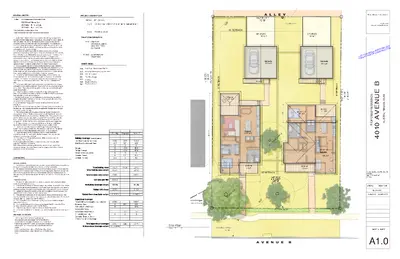
GENERAL NOTES Codes 2021 International Residential Code 2020 National Electric Code 2021 Uniform Plumbing Code 2021 Uniform Mechanical Code Visit link below for more information https://publicinput.com/2021TechnicalCodeChanges 1. It is the intent of these Contract Documents to establish a high quality level of material and workmanship, but not necessarily to note and call for every last item of work to be done. Any item not specifically covered but deemed necessary for satisfactory completion of the work shall be accomplished by the Contractor in a manner consistent with the quality of work without additional cost to the owner. All material and methods of installation shall be in accordance with industry standards and manufacturer's recommendations. 2. The Contractor shall be responsible for a thorough review of all drawings specifications and existing conditions prior to commencement of work. This includes but is not limited to site utilities and the structural scope of work. The failure of the Contractor to report discrepancies and seek modification or change prior to commencement of work shall be construed as full acceptance of the condition in question by the Contractor. The Contractor shall assume responsibility for all work depicted by the Contract Documents regardless of whether the Subcontractors agree as to whose jurisdiction certain areas of the scope of work are under. 3. It shall be assumed that the Contractor and the Subcontractors are sufficiently experienced to be considered qualified in their respective work responsibilities. The Contractor shall insure that the Owner receives acceptable workmanship common to the industry from all Subcontractors and material suppliers and is responsible for hiring qualified staff personnel and/ or Subcontractors as necessary. 4. The Contractor shall verify the location of all existing utilities so that the work may proceed safely and be coordinated among all Subcontractors and personnel involved. The Contractor shall notify the Owner and Designer in advance of any work required by public utility entities that will affect the cost of schedule of the work. 5. The contractor shall meet all safety requirements applicable in the city of Austin and maintain a safe working environment for all personnel and occupants during the entire project. The jobsite is to be kept orderly and as clean as possible during all construction activities. 6. This drawing set is provided to communicate only the basic design of the building. Structural design by others, all plumbing and Electrical shall also be design build and shall be coordinated by contractor. 7. Any errors and omissions or inconsistencies found in these drawings shall be brought to the Architects attention immediately. Do not proceed with work until all issues have been resolved in writing. 8. Do not scale the drawings, written dimensions take precedence over scale dimensions. 9. All new construction dimensions are drawn to the face of new studs as shown on the drawings. Any inconsistencies shall be brought to the Designer's attention prior to the commencement of work. 10. The Contractor shall verify all grades and grading requirements prior to the commencement of work. Grades shown are approximate, therefore all stairs and finish floor elevations shall be coordinated in the field. Note: Two consecutive steps shall constitute a stair, and stairs shall not exceed 7 3/4" rise or a 10" run per code. Mount one handrail per stair to continue the length of the run at 34" above the nosing typical. All stairs shall be built in conformance with all codes as applicable. 11. All 'clear' and 'minimum' dimensions shall be within 1/8" along it's full length. No adjustments shall be made without the Designer's prior written consent. 12. Locations of all partitions and doors shall be approved by the Designer or Owner in the field prior to construction. The Contractor shall notify the Designer or Owner of any conflicts or discrepancies in the location of new construction. 13. Larger scale drawings take precedence over small scale, details take precedence over all. Contractor shall notify the Designer of any discrepancies in writing prior to commencement of work. 14. The Contractor and Owner shall take responsibility to meet all code and manufacturer's requirements. It is the responsibility of the Builder to insure the project conforms to all codes applicable at the time of construction. Note: Manufacturers installation guidelines take precedence over diagrammatic details and drawings. Any inconsistencies shall be brought to the Owner's attention prior to the commencement of work. SITE NOTES EROSION CONTROL 1. The contractor shall install erosion/sedimentation controls and tree/natural area protective fencing prior to any site preparation work (clearing, grubbing or excavation). 2. The contractor is required to inspect the controls and fences at weekly intervals and after significant rainfall events to insure that they are functioning properly. The person(s) responsible for maintenance of controls and fences shall immediately make any necessary repairs to damaged areas. Silt accumulation at controls must be removed when the depth reaches six (6) inches. TREE PROTECTION 1. All trees and natural areas shown on plan to be preserved shall be protected during construction with temporary fencing. 2. Protective fences shall be erected according to City of Austin Standards for Tree Protection. 3. Protective fences shall be installed prior to the start of any site preparation work (clearing, grubbing or grading), and shall be maintained throughout all phases of the construction project. 4. Erosion and sedimentation control barriers shall be installed or maintained in a manner which does not result in soil build-up within tree drip lines. 5. Protective fences shall surround the trees or group of trees, and will be located at the outermost limit of branches (drip line) , for natural areas, protective fences shall follow the Limit of Construction line, in order to prevent the following: A. Soil compaction in the root zone area resulting from vehicular traffic or storage of equipment or materials; B. Root zone disturbances due to grade changes (greater than 6 inches cut or fill), or trenching not reviewed and authorized by the City Aborist; C. Wounds to exposed roots, trunk or limbs by mechanical equipment; D. Other activities detrimental to trees such as chemical storage, cement truck cleaning, and fires. VISITABILITY NOTES 1. At noted ground floor bathroom on plan provide: lateral two-inch by six-inch or larger nominal wood blocking installed flush with stud edges of bathroom walls. Centerline of the blocking must be 34 inches from and parallel to the interior floor level, except for the portion of the wall located directly behind the lavatory. 2. All light switches to be intalled at 48"aff to top of box, all wall outlets and receptacles must be installed minimum 15"aff to bottom of box. PROJECT DESCRIPTION Address: 4010 Avenue B Legal: LOT 28-30 & N 12.5FT LOT 27, BLK 7, HYDE PARK ADDN NO 2 Zoning: SF-3-HD-NCCD-NP PROJECT INFORMATION Owner: John Rosato 222 West Ave., suite 200 Austin, Texas 78701 512.784.4430 Architect: Donald Harris AIA 512.297.4206 SHEET INDEX A1.0 A1.0 A2.0 A2.1 A2.2 A3.0 A3.1 Cover Sheet / General Notes/ Site Plan Rendering of existing and proposed homes Floor Plans House 2 Floor Plans Garage Roof Plan Elevations- House 2 Elevations- House 2 Building & Impervious Coverage Existing Proposed House 2 Building Coverage (roofed areas) 1st Floor Conditioned Area 2nd Floor Conditioned Area Garage Garage Storage Wood Decks (covered) Covered Patios Covered Porches 1053 447 0 0 0 0 0 121 284 37 0 484 484 0 111 0 Total Building Area: Total Building Area on Lot: 1621 3021 1400 Total Covered Area on Lot: 2053 Lot Area per Plat: 11353 % Building Coverage on Lot: 18.1% Yielded Unit Areas: 2305 Yielded Floor Area Ratio on Lot: 0.2030 Impervious Coverage Total Building Coverage on Lot (above) Driveway Area Sidewalks & Walkways Uncovered Patios Uncovered Wood Decks Air Conditioner Pads Concrete Slabs or Decks Other Impervious Coverage 2053 0 91 9 381 50 9 1060 566 0 484 484 0 188 90 2872 2872 1822 16.0% 2110 0.1859 1822 381 100 50 18 A L L E Y S62°35'31"E 12.68' POWER POLE 609' 10' SETBACK DRIVEWAY 381 sq ft DRIVEWAY 381 sq ft ) ' 0 0 . 0 3 1 ( ' 6 0 . 0 3 1 ' W " 1 1 3 2 ° 2 6 N K C A B T E S ' 5 PORCH 188 sq ft GARAGE 484 sq ft GARAGE 484 sq ft 59 sq ft 56 sq ft K C A B T E S ' 5 ' E " 0 3 7 1 ° 2 6 S ' 0 3 . 0 3 1 ) ' 0 0 . 0 3 1 ( " 0 - ' 2 1 ADDITION 284 sq ft PORCH 111 sq ft " 2 1 / 3 - ' 4 5 HOUSE 1,060 sq ft 25.5" CREPE MYRTLE EXISTING HOUSE 1,050 sq ft PORCH 89 sq ft PORCH 121 sq ft Don Harris | Architect 512.297.4206 www.donharrisarchitect.com NOT FOR REGULATORY REVIEW PERMITTING OR CONSTRUCTION I E C N E D S E R D E S O P O R P B E U N E V A 0 1 0 4 1 5 7 8 7 S A X E T , I N T S U A FULL SCALE AS NOTED AT 22x34 HALF SCALE AT 11X17 JOB No. 2026-4010 REVISION 3/18/2026 SCHEMATIC SHEET NUMBER A1.0 5'-9 1/2" 27'-0" 28" POST OAK PROJECT NORTH 25' SETBACK LOT 28-30 & N 12.5FT LOT 27 11,353 sq ft 610' 87.10' S27°34'05"W A V E N U E B Total Impervious Coverage: 2153 440 2371 % Impervious Coverage on Lot: 43.7241% Site Plan SCALE: 1/8" = 1'-0" EXISTING SIDEWALK CURB Page 1 PROPOSED HOUSE RENOVATION HOUSE RENOVATION HOUSE ENLARGE REAR DORMER PROPOSED REAR ADDITION Don Harris | Architect 512.297.4206 www.donharrisarchitect.com NOT FOR REGULATORY REVIEW PERMITTING OR CONSTRUCTION I E C N E D S E R D E S O P O R P B E U N E V A 0 1 0 4 1 5 7 8 7 S A X E T , I N T S U A FULL SCALE AS NOTED AT 22x34 HALF SCALE AT 11X17 JOB No. 2026-4010 REVISION 3/18/2026 SCHEMATIC SHEET NUMBER A1.1 PORCH 3 A4.1 3 A4.1 12'-9" 3 A4.1 14'-3" 2 1 : 5 . .5:12 .5:12 10:12 10:12 DORMER 3:12 E G D R I 4 A4.1 4 A4.1 A4.1 10:12 E G D R I 10:12 2 1 3 : " 2 / 1 2 - ' 2 1 " 9 - ' 4 " 2 / 1 5 - ' 6 " 2 1 / 8 - ' 4 " 2 1 / 0 1 - ' 0 1 2-6x5-0 2-6x5-0 CLOSET 0 - 8 x 0 - 5 BEDROOM 3 2-8x8-0 2-4x8-0 0 - 8 x 4 - 2 HVAC 5'-8" 7'-0" 6 - 2 x 0 - 2 2-4x8-0 BATH 2 5'-3 1/2" 3'-1/2" 566.06 sq ft 2-4x8-0 2-4x8-0 2-8x8-0 DN 0 - 8 x 4 - 2 STAIR CLOSET DN CLOSET 0 - 8 x 0 - 5 BEDROOM 2 2-6x5-0 2-6x5-0 3'-7" 11'-1" 7'-11 1/2" " 2 / 1 3 - ' 8 " 2 / 1 8 - ' 6 " 2 - ' 4 1 " 2 1 / 6 - ' 5 " 1 1 - ' 6 " 2 / 1 8 - ' 2 1 0 - 3 x 6 - 2 0 - 3 x 6 - 2 " 0 - ' 9 3 " 1 1 - ' 1 1 " 2 / 1 1 1 - ' 8 " 3 - ' 7 " 2 1 / 0 1 - ' 0 1 " 2 / 1 3 - ' 4 5 " 2 / 1 3 - ' 9 3 4 A4.1 4 A4.1 Roof Plan SCALE: 1/4" = 1'-0" 3 A4.1 27'-0" 3 A4.1 Second Floor SCALE: 1/4" = 1'-0" 2-6x5-0 2-6x5-0 2-6x5-0 BANQUETTE 2-10x8-0 SCREENED PORCH 10-0x8-0 0 - 5 x 6 - 2 0 - 5 x 6 - 2 PIANO BAR MICRO G R W D KITCHEN REF PANTRY LIVING ROOM CLOSET 2-6x8-0 BATH 0 - 8 x 8 - 2 2-6x8-0 CLOSET 0 - 8 x 0 - 2 STAIR BENCH/ HOOKS/CABS MUDROOM 0 - 8 x 8 - 2 1,060 sq ft 0 - 8 x 8 - 2 ENTRY 2-8x8-0 POWDER W/DW/D 3-0x8-0 2-6x4-0 BEDROOM 0 - 6 x 6 - 2 COVERED PORCH 2-6x6-0 2-6x6-0 STEPS 12'-9" 12'-9" Don Harris | Architect 512.297.4206 www.donharrisarchitect.com NOT FOR REGULATORY REVIEW PERMITTING OR CONSTRUCTION " 2 / 1 3 - ' 8 I E C N E D S E R D E S O P O R P B E U N E V A 0 1 0 4 1 5 7 8 7 S A X E T , I N T S U A " 0 - ' 9 3 4 A4.1 FULL SCALE AS NOTED AT 22x34 HALF SCALE AT 11X17 JOB No. 2026-4010 REVISION " 0 - ' 7 3/18/2026 SCHEMATIC " 2 - ' 7 " 2 / 1 8 - ' 3 1 " 2 / 1 6 - ' 3 " 9 - ' 3 " 2 1 / 0 1 - ' 0 1 0 - 4 x 0 - 2 0 - 4 x 0 - 2 0 - 4 x 6 - 2 0 - 6 x 6 - 2 Proposed Floor Plan SCALE: 1/4" = 1'-0" 3 A4.1 PROJECT NORTH SHEET NUMBER A2.0 6 A4.1 6 A4.1 2-6x5-0 2-6x5-0 10:12 E G D R I 10:12 STORAGE 484.00 sq ft 5 A4.1 5 A4.1 5 A4.1 5 A4.1 2 1 : 1 2-8x6-8 2-6x5-0 STAIR Roof Plan SCALE: 1/4" = 1'-0" Second Floor SCALE: 1/4" = 1'-0" Don Harris | Architect 512.297.4206 www.donharrisarchitect.com NOT FOR REGULATORY REVIEW PERMITTING OR CONSTRUCTION I E C N E D S E R D E S O P O R P B E U N E V A 0 1 0 4 1 5 7 8 7 S A X E T , I N T S U A FULL SCALE AS NOTED AT 22x34 HALF SCALE AT 11X17 JOB No. 2026-4010 REVISION 3/18/2026 SCHEMATIC 5 A4.1 H T R O N T C E J O R P SHEET NUMBER A2.1 6 A4.1 22'-0" 8-0x7-0 8-0x7-0 GARAGE STAIR 3-0x6-8 " 0 - ' 2 2 5 A4.1 Garage Plan SCALE: 1/4" = 1'-0" REMOVE DECK REMOVE BATH REMOVE ALL WINDOWS RG REMOVE ALL KITCHEN FIXTURES AND ACCESSORIES REMOVE WALL 1 A4.0 19'-1/2" 13'-10 1/2" 12'-3" 6'-9 1/2" 2-6x6-0 2-6x6-0 " 8 - ' 0 1 CLOSET 284 sq ft BEDROOM 7'-10" 3'-11 1/2" PANTRY D W COVERED PORCH 10-0x8-0 KITCHEN W D F E R G R " 0 - ' 2 1 0 - 6 x 6 - 2 0 - 6 x 6 - 2 5 - 6 x 6 - 2 STAIR HVAC 2 A4.0 STAIR HVAC HALL DEN 1,053 sq ft COVERED PORCH First Floor Demolition SCALE: 1/4" = 1'-0" " 7 - ' 3 " 0 - ' 7 CLOSET DEN 5 - 6 x 6 - 2 CLOSET CLOSET HALL POWDER 3'-3 1/2" 1,053 sq ft LIVING ROOM LIVING ROOM 2-6x6-5 2-6x6-5 COVERED PORCH 5 - 6 x 6 - 2 2-6x6-5 2-6x6-5 Proposed Floor Plan SCALE: 1/4" = 1'-0" Don Harris | Architect 512.297.4206 www.donharrisarchitect.com NOT FOR REGULATORY REVIEW PERMITTING OR CONSTRUCTION I E C N E D S E R D E S O P O R P B E U N E V A 0 1 0 4 1 5 7 8 7 S A X E T , I N T S U A FULL SCALE AS NOTED AT 22x34 HALF SCALE AT 11X17 JOB No. 2026-4010 REVISION 3/18/2026 SCHEMATIC " 0 - ' 8 " 0 - ' 4 5 - 6 x 6 - 2 5 - 6 x 6 - 2 5 - 6 x 6 - 2 2 A4.0 1 A4.0 PROJECT NORTH SHEET NUMBER A2.2 REMOVE DORMER REMOVE BATH REMOVE ALL WINDOWS 2 East 61st Street at Fi.h Avenue 2 East 61st Street at Fi.h Avenue New York City, NY 10065 New York City, NY 10065 447 sq ft REMOVE ALL WINDOWS 1 A4.0 2-6x5-0 2-6x5-0 BEDROOM 3 36.77 sq ft EXISTING STAIR PROVIDE RAILING AT INSIDE CLOSET 0 - 5 x 6 - 2 2 A4.0 2-8x6-8 8 - 6 x 6 - 2 BATH 2 N D STAIR 447.14 sq ft N D 2-8x6-8 BEDROOM 2 CLOSET 0 - 5 x 0 - 5 2-6x5-0 2-6x5-0 2 A4.0 " 9 - ' 9 " 8 - ' 5 " 4 - ' 1 1 Don Harris | Architect 512.297.4206 www.donharrisarchitect.com NOT FOR REGULATORY REVIEW PERMITTING OR CONSTRUCTION I E C N E D S E R D E S O P O R P B E U N E V A 0 1 0 4 1 5 7 8 7 S A X E T , I N T S U A FULL SCALE AS NOTED AT 22x34 HALF SCALE AT 11X17 JOB No. 2026-4010 REVISION 3/18/2026 SCHEMATIC Second Floor Demolition SCALE: 1/4" = 1'-0" Second Floor SCALE: 1/4" = 1'-0" 1 A4.0 PROJECT NORTH SHEET NUMBER A2.3 COMPOSITION SHINGLE ROOF WOOD CLAD DOUBLE HUNG WINDOWS CEMENT BOARD LAP SIDING 12 10 " 0 - ' 9 " 0 - ' 9 PIER AND BEAM FOUNDATION W/ PLASTER UNDERPINNING East 4010(facade) SCALE: 1/4" = 1'-0" West 4010 SCALE: 1/4" = 1'-0" South 4010 SCALE: 1/4" = 1'-0" Don Harris | Architect 512.297.4206 www.donharrisarchitect.com NOT FOR REGULATORY REVIEW PERMITTING OR CONSTRUCTION I E C N E D S E R D E S O P O R P B E U N E V A 0 1 0 4 1 5 7 8 7 S A X E T , I N T S U A FULL SCALE AS NOTED AT 22x34 HALF SCALE AT 11X17 JOB No. 2026-4010 REVISION 3/18/2026 SCHEMATIC SHEET NUMBER A3.0 West at Garage SCALE: 1/4" = 1'-0" East @ Garage SCALE: 1/4" = 1'-0" North 4010 SCALE: 1/4" = 1'-0" Don Harris | Architect 512.297.4206 www.donharrisarchitect.com NOT FOR REGULATORY REVIEW PERMITTING OR CONSTRUCTION I E C N E D S E R D E S O P O R P B E U N E V A 0 1 0 4 1 5 7 8 7 S A X E T , I N T S U A FULL SCALE AS NOTED AT 22x34 HALF SCALE AT 11X17 JOB No. 2026-4010 REVISION 3/18/2026 SCHEMATIC SHEET NUMBER A3.1 East (facade ) 4010 1/2 SCALE: 1/4" = 1'-0" West 4010 1/2 SCALE: 1/4" = 1'-0" South 4010 1/2 SCALE: 1/4" = 1'-0" Don Harris | Architect 512.297.4206 www.donharrisarchitect.com NOT FOR REGULATORY REVIEW PERMITTING OR CONSTRUCTION I E C N E D S E R D E S O P O R P B E U N E V A 0 1 0 4 1 5 7 8 7 S A X E T , I N T S U A FULL SCALE AS NOTED AT 22x34 HALF SCALE AT 11X17 JOB No. 2026-4010 REVISION 3/18/2026 SCHEMATIC SHEET NUMBER A3.2 East @ Garage SCALE: 1/4" = 1'-0" West at Garage SCALE: 1/4" = 1'-0" North 4010 1/2 SCALE: 1/4" = 1'-0" Don Harris | Architect 512.297.4206 www.donharrisarchitect.com NOT FOR REGULATORY REVIEW PERMITTING OR CONSTRUCTION I E C N E D S E R D E S O P O R P B E U N E V A 0 1 0 4 1 5 7 8 7 S A X E T , I N T S U A FULL SCALE AS NOTED AT 22x34 HALF SCALE AT 11X17 JOB No. 2026-4010 REVISION 3/18/2026 SCHEMATIC SHEET NUMBER A3.3 Don Harris | Architect 512.297.4206 www.donharrisarchitect.com BATH NOT FOR REGULATORY REVIEW PERMITTING OR CONSTRUCTION BEDROOM BEDROOM LIVING ROOM KITCHEN PORCH STAIR HALL KITCHEN 1 Building Section SCALE: 1/4" = 1'-0" 2 Building Section SCALE: 1/4" = 1'-0" I E C N E D S E R D E S O P O R P B E U N E V A 0 1 0 4 1 5 7 8 7 S A X E T , I N T S U A FULL SCALE AS NOTED AT 22x34 HALF SCALE AT 11X17 JOB No. 2026-4010 REVISION 3/18/2026 SCHEMATIC SHEET NUMBER A4.0 " 0 - ' 9 " 0 - ' 9 3 Building Section SCALE: 1/4" = 1'-0" " 2 1 / 3 - ' 3 1 " 6 - ' 4 " 0 - ' 8 4 Building Section SCALE: 1/4" = 1'-0" 5 A4.1 4 ' - 6 " " 0 - ' 8 STORAGE GARAGE 5 Building Section SCALE: 1/4" = 1'-0" 6 Building Section SCALE: 1/4" = 1'-0" Don Harris | Architect 512.297.4206 www.donharrisarchitect.com NOT FOR REGULATORY REVIEW PERMITTING OR CONSTRUCTION I E C N E D S E R D E S O P O R P B E U N E V A 0 1 0 4 1 5 7 8 7 S A X E T , I N T S U A FULL SCALE AS NOTED AT 22x34 HALF SCALE AT 11X17 JOB No. 2026-4010 REVISION 3/18/2026 SCHEMATIC SHEET NUMBER A4.1