03.2 - BSRB BCER Public Release Redacted 2023.12.08_Part2 — original pdf
Backup
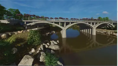
C-2 - Draft Interim Bridge Status Memorandum – Feb 2022 Barton Springs Rd. Bridge over Barton Creek Interim Bridge Status REVISIONS Project: City of Austin – Barton Springs Road Bridge over Barton Creek Document: Interim Bridge Status Memorandum Revision Date of Issue Description D0 D1 D2 01/17/19 01/25/19 02/24/22 Draft Issue for Internal Comment Draft Issue for City Management Team Review/Comment Draft Issue for City Management Team Review/Comment Statement of Limitations This report is intended for the City of Austin and is not to be distributed to third parties outside the City’s organization. This interim memo provides an update regarding the status of the conceptual design work performed by URS for the proposed facility. This work is ongoing and not complete. Information included in this memo is subject to change prior to release of the Final Bridge Conceptual Engineering Report. Page ii Barton Springs Rd. Bridge over Barton Creek Interim Bridge Status CONTENTS PAGE 1. 2. INTRODUCTION............................................................................................ 1 Background ........................................................................................... 1 1.1 Project Objectives .................................................................................. 1 1.2 Bridge Engineering Process ...................................................................... 2 1.3 1.3.1 Preliminary Selection and Concept Engineering – Process Phase 1 ...... 2 1.3.2 Preliminary Selection and Concept Engineering – Process Phase 2 ...... 3 1.3.3 Preliminary Selection and Concept Engineering – Process Phase 3 ...... 3 2.4 2.5 SUMMARY OF RESULTS ................................................................................. 4 Bridge Cultural/Historical Background ....................................................... 4 2.1 Barton Springs/Azie Morton Road Intersection Assessment .......................... 4 2.2 Roadway Alignment Concepts (Rehabilitation vs Replacement) .................... 4 2.3 2.3.1 Rehabilitation Option .................................................................... 4 2.3.2 Replacement Option ..................................................................... 5 Maintenance of Traffic / Construction Phasing ............................................ 5 2.4.1 Phase 1 (Figure 2-3) ..................................................................... 5 2.4.2 Phase 2 (Figure 2-4) ..................................................................... 6 2.4.3 Phase 3 (Figure 2-5) ..................................................................... 6 2.4.4 Final Tasks – Complete Construction............................................... 7 Bridge Rehabilitation Summary ................................................................ 7 2.5.1 Introduction ................................................................................ 7 2.5.2 Bridge Rehabilitation Feasibility ...................................................... 7 2.5.3 Description of Existing Condition .................................................... 7 2.5.4 Service Life Estimates ................................................................... 8 2.5.5 Existing Structure - Load Capacity Estimates ................................... 9 2.5.6 Rehabilitation Concept and Components ........................................ 10 2.5.7 Rehabilitation Renderings ............................................................ 11 2.5.8 Estimated Costs ......................................................................... 11 Bridge Replacement Summary ............................................................... 12 2.6.1 Introduction .............................................................................. 12 2.6.2 Bridge Replacement Feasibility ..................................................... 12 2.6.3 Replacement Concept and Components ......................................... 12 2.6.4 Estimated Costs ......................................................................... 13 Conceptual Zilker Park/Pedestrian Opportunities ...................................... 13 2.7.1 Structure/Tree Protection and Mitigation ....................................... 14 2.7.2 Zilker Park – Zilker Zephyr .......................................................... 14 2.7.3 Zilker Park Hike/Bike Trail ........................................................... 14 2.7.4 Barton Springs Road ................................................................... 15 2.7.5 Azie Morton Road ....................................................................... 15 2.7.6 Bridge Pedestrian Enhancements ................................................. 15 Pedestrian Maintenance of Traffic Conceptual Plan .................................... 15 Preliminary Environmental Issues/Permits ............................................... 16 2.8 2.9 2.6 2.7 3. COMPARISON OF PRELIMINARY REPLACEMENT / REHABILITATION CONCEPTS .................................................................................................. 44 4. REFERENCES .............................................................................................. 47 Page iii Barton Springs Rd. Bridge over Barton Creek Interim Bridge Status LIST OF TABLES Table 2-1. 1925 Original Structure Rating Summary ....................................................... 9 Table 2-2. 1945 Widened Structure Rating Summary ...................................................... 9 Table 2-3. Preliminary Federal/State/City of Austin Permits and Approvals for the Barton Springs Road Bridge Project .................................................................. 18 Table 3-1. Comparison of Bridge Rehabilitation / Replacement Concepts ......................... 44 LIST OF EXHIBITS / FIGURES Exhibit 2-1. Roadway/Sidewalk Cross-Section Rehabilitation Option Concept ................... 10 Exhibit 2-2. Features of Rehabilitated Bridge ............................................................... 11 Figure 2-1. Rehabilitation Option – Plan and Cross Section ............................................ 24 Figure 2-2. Replacement Option – Plan and Cross Section ............................................. 25 Figure 2-3. Maintenance of Traffice (MOT) Plan Phase 1 ................................................ 26 Figure 2-4. Maintenance of Traffice (MOT) Plan Phase 2 ................................................ 27 Figure 2-5. Maintenance of Traffice (MOT) Plan Phase 3 ................................................ 28 Figure 2-6. Maintenance of Traffice (MOT) Plan Complete .............................................. 29 Figure 2-7. Rehabilitation Concept Sequence of Construction Step 1 ............................... 30 Figure 2-8. Rehabilitation Concept Sequence of Construction Step 2 ............................... 31 Figure 2-9. Rehabilitation Concept Sequence of Construction Step 3 ............................... 32 Figure 2-10. Rehabilitation Concept Sequence of Construction Step 4 ............................. 33 Figure 2-11. Rehabilitation Concept Sequence of Construction Step 5 ............................. 34 Figure 2-12. Rehabilitation Concept Sequence of Construction Completed ....................... 35 Figure 2-13. Replacement Concept 1 Single Arch_01 .................................................... 36 Figure 2-14. Replacement Concept 2 "Y" Pier ............................................................... 37 Figure 2-15. Replacement Concept 3 Conventional Pier ................................................. 38 Figure 2-16. Bridge Deck – Northern Pedestrian Path .................................................... 39 Figure 2-17. Bridge Deck – Southern Pedestrian Path ................................................... 40 Figure 2-18. Conceptual Pedestrian Access Plan ........................................................... 41 Figure 2-19. Pedestrian Maintenance of Traffic Conceptual Plan ..................................... 42 Figure 2-20. Preliminary Environmental Constraints Map ............................................... 43 Page iv Barton Springs Rd. Bridge over Barton Creek Interim Bridge Status 1. INTRODUCTION 1.1 Background URS is under contract to the City of Austin to conduct a variety of tasks to evaluate rehabilitation or replacement options for the Barton Springs Road Bridge over Barton Creek. The location of the bridge, at the entrance to Zilker Park, is a focal point of key community events such as the Austin City Limits Music Festival, South by Southwest Conference and Music Festival (SXSW), Barton Springs, Trail of Lights, and Blues on the Green. Barton Springs Rd. and the associated bridge is also a key connection for vehicular, bike, and pedestrian access linking Mopac to downtown and the South Lamar/Congress corridors, as well as providing the primary northern entrance to the Zilker and Barton Hills neighborhoods via Azie Morton Rd., located immediately east of the bridge. The three-span open spandrel concrete arch bridge was originally built in 1925 and was expanded to the north in 1946. The current bridge is 212’ long and 58’-8” wide. The age of the structure has warranted progressively more detailed inspection and condition assessments over time. In addition, the bridge geometry is functionally obsolete with respect to bikes and pedestrians, and the roadway west of Azie Morton is un-aligned with the roadway east of Azie Morton. The City’s preliminary bridge deck concept approximately doubles the width of the bridge deck to accommodate wider sidewalks on either side of the bridge, two bicycle lanes, four travel lanes, and a median to match the cross section of Barton Springs Road established by a previous reconstruction of that roadway east of Azie Morton. The bridge is currently a bottle-neck, with congestion for all modes of travel at the Barton Springs Road/Azie Morton intersection. The proximity of the bridge and Azie Morton intersection (including structural cantilevered sidewalk) specifies the two features are integral to one another. For that reason, in addition to the evaluation of the bridge structure, the City is interested in understanding the potential for reducing congestion at this intersection and entrance to Zilker Park via assessment of potential improvements to the combination of roadway, bridge, and intersection. Reducing congestion will provide future benefits to the local neighborhoods, commuters (all travel modes), local businesses, as well as Zilker Park users and event attendees. 1.2 Project Objectives URS has been contracted (C.I.P. Project Number 5873.031) to provide design services for rehabilitation or replacement of the existing bridge. The original project scope included consideration of two potential bridge rehabilitation options and additional options for bridge replacement. A general description of these options is: • Rehabilitation Option 1: One option to rehabilitate and preserve the existing structure… This option must include consideration of a retrofit… bridge railing system to upgrade the substandard existing railings. This option also includes consideration and feasibility of a complementary structure or other means to adequately address additional capacity desired for bike and pedestrian traffic on both sides of the bridge. • Rehabilitation Option 2: One option to rehabilitate the existing structure and enhance the deck by widening it to incorporate wider sidewalks and a bike lane on both sides. This new bridge deck option may either be placed on the existing substructure or a widened, expanded substructure as necessary. Page 1 Barton Springs Rd. Bridge over Barton Creek Interim Bridge Status • Replacement Options: Three options for complete reconstruction of the bridge designed to modern structural codes to include a wider bridge deck to allow for realigning the Barton Springs Road intersection for improved safety, bike lanes on both sides, and wider ADA compliant sidewalks. 1.3 Bridge Engineering Process The overall process envisioned for the bridge rehabilitation/replacement is as follows: • Preliminary Selection and Concept Engineering. This phase will assess the feasibility of bridge rehabilitation or replacement. Based on the preferred option, this phase will also select the bridge type and style, and preliminary concept options; this will include preliminary design options and conceptual evaluations of each option. The evaluations will consist of assessments such as bridge structural engineering, architectural, roadway, utilities, and environmental feasibility. These options will be supported, and the evaluations vetted by City of Austin stakeholder departments and executive management. Public involvement will be conducted, with specific stakeholder and public meetings conducted at strategic milestones. The result of the Preliminary Selection phase will be a vetted/selected bridge design option; this phase will be documented in a Bridge Conceptual Engineering Report (BCER). The confirmed design option will then proceed to the design phase. • Preliminary (30%) Design. This phase consists of the 30% Design and the Preliminary Engineering Report. The primary outcomes of this phase include obtaining detailed information from onsite topographic and bathymetric surveying, engineering field investigations. This detailed information will allow for preliminary detailed engineering of bridge and roadway areas. It will also allow for early coordination with federal, state, and local permitting agencies to vet the design and determine the available strategies for obtaining permits/approvals of the design to support bidding/construction. investigations, and environmental field • Final Design and Permitting. Includes detailed design for all disciplines, and obtaining permits and approvals from all federal, state, and City agencies and departments. • Bidding and Construction. This phase includes obtaining bids and City contracting for the Construction Contractor and managing the construction process. 1.3.1 Preliminary Selection and Concept Engineering – Process Phase 1 Due to funding limitations, the overall Preliminary Selection process was divided into smaller scopes of work. The first scope of work (Phase 1) was the Bridge Inspection and Condition Assessment. The objective of this phase was to understand the condition of the existing bridge based on a detailed visual inspection and selected sampling/testing of the bridge concrete. It was also understood that the results of this phase may provide insight into the viability of one or both rehabilitation options. The Bridge Inspection and Condition Assessment Report for Barton Springs Road Bridge [R-1] was submitted in January 2017. The condition assessment report indicated that the overall bridge was in fair condition; however, the deck (with integral longitudinal joint), floor beams, and spandrel columns had exhibited the most degradation, although all structural components had exhibited some degradation. As a result, any rehabilitation desiring increased service life would need to remove the deck, floor beams, and spandrel columns, essentially stripping the Page 2 Barton Springs Rd. Bridge over Barton Creek Interim Bridge Status structure down to the arch ribs as a starting point. As indicated in the report, these results, by definition, remove Rehabilitation Option 1 as a feasible alternative, since the intent of that option was a "low-impact", “preserve-structure” rehabilitation option from visual, construction, and cost standpoints. Based on the above, the URS Team is focusing on Rehabilitation Option 2 and on potential bridge replacement options moving forward. 1.3.2 Preliminary Selection and Concept Engineering – Process Phase 2 The second scope of work, and the subject of this memorandum, expands on the bridge condition inspection, and focuses on: • Load capacity and rehabilitation analysis of the existing bridge; • An assessment of roadway/intersection needs and intersection options to replacement and the options associated with bridge complement rehabilitation; • Structural assessment of Rehabilitation Option 2; • Development and assessment of three bridge replacement concepts/options; and • Preliminary costing for the rehabilitation and replacement options. The intent of Phase 2 is to provide the City an understanding of the roadway/ intersection/bridge needs and options to meet those needs, in order to guide the remaining phases of concept and design refinement and bridge selection. 1.3.3 Preliminary Selection and Concept Engineering – Process Phase 3 Phase 3 and beyond will provide the remainder of the Preliminary Selection phase, and will focus on the full vetting of the rehabilitation and/or replacement options. Page 3 Barton Springs Rd. Bridge over Barton Creek Interim Bridge Status 2. SUMMARY OF RESULTS This section of the report summarizes the work performed as part of this Phase 2 Scope of work, and associated technical findings. 2.1 Bridge Cultural/Historical Background The original Barton Springs Road bridge was built in 1925 and widened to its current configuration in 1945. The bridge is located adjacent to Zilker Park, which is listed in the National Register of Historic Places (NRHP); the bridge is considered a contributing resource to the Park. The Barton Springs Archeological and Historical District (formed in 1985) is also located within the Zilker Historic District and the downstream boundary of this district is in close proximity to the bridge. The work performed to date has focused primarily on the roadway and structural feasibility and concepts associated with future bridge rehabilitation or replacement options. It is understood that all future planning and design work will also include coordination and discussions with key cultural/historic preservation stakeholders such as the City’s Parks and Recreation Department (PARD) and Historic Preservation Office, as well as the Texas Historic Commission (THC). 2.2 Barton Springs/Azie Morton Road Intersection Assessment As discussed above, the location of the bridge, at the entrance to Zilker Park, is a focal point of key community events and gatherings such as the Austin City Limits Music Festival. Barton Springs Road (and bridge) is also a key commuter corridor with access to Mopac and Bee Caves Road, as well as being a key entry/exit to the Zilker and Barton Hills neighborhoods via Azie Morton Road. The Azie Morton Road intersection, due to this proximity, is integral to any future bridge work. In addition to the evaluation of the bridge structure, a traffic analysis was conducted in the area to understand the potential for reducing congestion at the Barton Springs/Azie Morton intersection and entrance to Zilker Park. Existing traffic counts and intersection turning movements were reviewed and anticipated traffic growth patterns through the year 2040 were incorporated. The results of the study indicated that inclusion of right turn bays for both Barton Springs Rd. and Azie Morton Road would improve vehicle operations and reduce delays during peak hour traffic. Accordingly, these improvements were incorporated into the concept development for both bridge rehabilitation and replacement. 2.3 Roadway Alignment Concepts (Rehabilitation vs Replacement) The existing centerline alignment of Barton Springs Road contains a Point of Intersection (PI) within or near the Azie Morton Road intersection. The effects of this PI appear worse in the westbound (WB) direction due to the narrow existing bridge and forced lane shift across the intersection related to the existing WB left turn lane to Azie Morton. This adverse geometry can be alleviated somewhat with the Rehabilitation Option (see Figure 2-1), but is entirely resolved with the Replacement Option (see Figure 2-2). 2.3.1 Rehabilitation Option The Rehabilitation Option will reuse portions of the existing bridge structure (with rehabilitation measures implemented) and widen each side to provide the ultimate width necessary for proposed multi-modal travel ways. Due to complexities involved Page 4 Barton Springs Rd. Bridge over Barton Creek Interim Bridge Status in variable-width bridge widening, it is not feasible to adjust the Barton Springs Road centerline alignment bearing along the bridge in the Rehabilitation Option. Proposed improvements in this option include: widened pedestrian paths, potential for additional pedestrian amenities along the north side, improved bicycle facilities, maintain two vehicle travel lanes in each direction, full-width median opposite the WB left turn lane to Azie Morton, eastbound (EB) right turn lane to Azie Morton, and northbound (NB) right turn lane from Azie Morton to Barton Springs Road. However, the PI condition will remain, and future drivers will experience a slight shift as they travel through the Azie Morton intersection. 2.3.2 Replacement Option The Replacement Option will remove the existing bridge structure in its entirety and provide a new structure with the ultimate width necessary for proposed multi-modal travel ways. The proposed structure will be designed with the centerline alignment bearing matching the existing roadway east of Azie Morton. This will require a minor transition within the centerline radius just west of Barton Creek that will not contain a PI and will meet current City of Austin design requirements. This revised centerline alignment can accommodate the preservation of the historic stone monuments marking the entrance to Zilker Park. Proposed improvements in this option include the same benefits listed under the Rehabilitation Option with the added benefit of having a consistent alignment that meets current design standards and eliminates the PI condition within or near the Azie Morton intersection. Additionally, this option allows for lengthening the bridge by moving the western abutment to the west, In so doing, the Replacement Option provides additional space to facilitate improvements to existing Zilker Park facilities, such as walking paths and the Zilker Zephyr miniature railroad, both of which pass under the Barton Springs Road Bridge on the west bank. This additional space for improvements is not feasible with the Rehabilitation Option. 2.4 Maintenance of Traffic / Construction Phasing General Construction Phasing and Maintenance of Traffic (MOT) during construction are similar for both Rehabilitation and Replacement Options. Due to the nature of this key commuter corridor and special events center, and due to the anticipated duration of the bridge construction, it was thought to be essential to maintain all four lanes of traffic in operation during bridge construction. It is currently planned to include three phases of construction, maintaining two traffic lanes in each direction with traffic shifts between each phase to accommodate the subsequent phases of work. There are likely to be occasional lane closures for specific components of the work or to facilitate material and/or equipment loading and unloading, but these should be limited to off-peak hours. More specific descriptions of each phase are in the sections below and illustrated in Figures 2-3 to 2-5. An illustration of the completed plan view and typical section is shown in Figure 2-6. 2.4.1 Phase 1 (Figure 2-3) Phase 1 of the MOT will be split into 2 Steps to maximize vehicle and pedestrian movement through the project. Phase 1 Step 1 • Shift traffic along Azie Morton Road over to the west to setup a work zone on the east side of Azie Morton. Construct proposed retaining wall, right turn Page 5 Barton Springs Rd. Bridge over Barton Creek Interim Bridge Status lane, and new sidewalk on Azie Morton. Pedestrian traffic will be unaffected by this phase of MOT and can continue to travel on existing facilities. Phase 1 Step 2 • Maintain traffic along Barton Springs Road generally in existing locations with appropriate protections (concrete barriers and advanced warning devices) installed to inform and protect traveling public and to protect construction workers, materials, and equipment. • Detour pedestrian traffic wanting to cross Barton Springs from Azie Morton along east side of Azie Morton on newly constructed sidewalk. A temp crossing will be set up on the east side of the Azie Morton / Barton Springs intersection. • Construct north and south portions of Barton Springs Road bridge / approach pavement with appropriate permanent and temporary barriers as well as retaining wall and pavement cantilevered sidewalk along east side of Azie Morton Road. • Proposed improvements constructed during this phase will facilitate traffic operations during construction and then can be further developed to provide enhanced pedestrian amenities such as unique gathering places and/or overlooks to Barton Creek and Lady Bird Lake with direct pedestrian connections to trails passing under the bridge along Barton Creek. 2.4.2 Phase 2 (Figure 2-4) • Update MOT signs, structures, and devices to facilitate Phase 2 work. • Split WB traffic along Barton Springs Road. One lane will be routed onto the new bridge constructed during Phase 1, and the other lane will be routed down the existing outside lane of WB traffic. • Split EB traffic along Barton Springs Road. One lane will be diverted to what was the inside lane of WB traffic, and the other will be routed onto the new bridge constructed in Phase 1. • Shift NB and SB traffic along Azie Morton Road to the east onto pavement completed during Phase 1. • Demolish (for replacement) or redeck (for rehabilitation) existing EB bridge. • Shift EB pedestrian traffic from the existing bridge to the new bridge constructed in Phase 1. • Construct southern interior portion of proposed Barton Springs Road bridge and approach pavement. 2.4.3 Phase 3 (Figure 2-5) • Update MOT signs, structures, and devices to facilitate Phase 3 work. • Split WB traffic along Barton Springs Road. One lane will continue on the bridge built in Phase 1. The other lane will be shifted south onto the new bridge built in Phase 2. • Split EB traffic along Barton Springs Road. One lane will remain on the bridge built in Phase 1. The other lane will be routed onto the bridge built in Phase 2. To make the geometry of this shift work, the left turn off of Barton Springs Road onto Azie Morton Road will need to be closed. The left turn can still be made, it will just need to be combined with the straight lane. • Maintain pedestrian traffic as it was in Phase 2. • Demolish (for replacement) or redeck (for rehabilitation) existing WB bridge. • Construct northern interior portion of proposed Barton Springs Road bridge and approach pavement. Page 6 Barton Springs Rd. Bridge over Barton Creek Interim Bridge Status 2.4.4 Final Tasks – Complete Construction • Update MOT signs, structures, and devices to facilitate final tasks for bridge completion. Remove temporary features no longer needed. • Route all Barton Springs Road traffic onto permanent approach pavement and bridge completed in previous phases – shift lanes toward median to extent necessary to construct barriers between roadway and pedestrian areas. • Shift vehicle and pedestrian traffic into final proposed locations after miscellaneous elements are completed. Remove all remaining temporary features and perform final site cleanup for project acceptance by the City. 2.5 Bridge Rehabilitation Summary 2.5.1 Introduction As discussed above, the URS Team has performed an assessment of Rehabilitation Option 2, taking into consideration the roadway geometry and MOT needs. The rehabilitation of the existing structure within the proposed widened cross section is considered a feasible design alternative. This alternative provides for preservation – primarily through concrete remediation and cathodic protection methods – of the existing bridge main arch and substructure elements. However, replacement of the existing bridge deck, floor system, and arch spandrel columns is required based upon the amount of deterioration present in these reinforced concrete elements. Detailed information regarding the condition evaluation of the existing bridge elements was provided in the 2017 Bridge Inspection and Condition Assessment Report by URS and the associated 2017 On-Site Sampling and Laboratory Investigation by CTL Group. 2.5.2 Bridge Rehabilitation Feasibility The feasibility of the proposed design alternative has been studied in the context of providing the following requirements: • Required roadway section; • Load-carrying capacity in accordance with the current AASHTO LRFD Design Code; • Aesthetic compatibility with respect to the original structure(s); • Future remaining service life that is comparable to that of a replacement structure; and • Construction cost that is competitive with that of a replacement structure. It is still too early in the planning process to develop detailed architectural styles or designs and coordinate same with the THC and stakeholders. Based on previous discussions with THC related to similar types of projects, the new bridge elements constructed as part of an overall rehabilitation should not be a replica of, but be complementary to, the existing bridge elements. Reconstruction/rehabilitation will be accomplished in individual stages with no reduction of the existing roadway lane capacity as in the above MOT descriptions; however, pedestrian traffic will be limited periodically and required to detour during the reconstruction. Also, extensive temporary falsework with associated foundations within Barton Creek will be required to support new portions of the bridge rehabilitation while it is being constructed. 2.5.3 Description of Existing Condition The south structure is 97 years old, and the north structure is 76 years old. The bridge overall has a condition rating of "Fair," and most structural components Page 7 Barton Springs Rd. Bridge over Barton Creek Interim Bridge Status generally have a condition rating of “Good”, based on the FHWA Condition Rating Guidelines. As indicated by the recommendations of the 2017 Bridge Inspection and Condition Assessment Report, the preferred method of mitigating corrosion of the existing bridge elements is to limit water intrusion through the deck. With respect to the arch ribs and piers, the main load-carrying members, the results of the concrete testing indicate that the concrete quality is generally good. However, additional steps to implement means of cathodic protection into the structure are also desired, since the depths of carbonation and chloride content at some locations in the arch ribs are at the level of the reinforcement and at a concentration consistent with the threshold for initiation of corrosion of the reinforcing bars. Given the advanced age of the deck, and the fact that the most serious deterioration is found within the vicinity of the longitudinal deck joint, it is preferable to replace the deck entirely and eliminate the longitudinal joint and transverse joints where practical. In addition, the spandrel columns exhibit low concrete compressive strength and severe cracking, spalling, and/or delamination (2017 On-Site Sampling and Laboratory Investigation). The cracking of the shorter spandrel columns is further exacerbated by their structural configurations (moment connections at both the top and bottom), which attract an inordinately large amount of shear loading. Therefore, any proposed bridge rehabilitation strategy that provides a substantial increase in service life requires “stripping” the structure down to the arch ribs and reconstructing the spandrel columns, floor system, and deck. Unknown Information: Some key unknown information that requires further investigation includes the following items: • The results of a future concrete corrosion Inspection and Testing Program to better identify the levels of corrosion of existing bridge elements to remain in place. The outcome of this sampling and testing work may indicate that rehabilitation is not practical or feasible with respect to the estimated remaining service life of the original bridge elements. • The effects upon existing foundations from adjacent construction on existing or new foundations. • The existing West Abutment foundation – the original drawings appear to indicate that the bridge foundation is in fine-grained soils and not on limestone. Additional investigations are warranted, and pending these results, additional foundation remediation may be required. Each of these items can likely be contained within the contingent cost ranges developed for the bridge rehabilitation described below; however, the final condition of the existing bridge elements to remain could possibly discourage or disqualify this design alternative. 2.5.4 Service Life Estimates It is currently estimated that the bridge structure will begin to require significant maintenance in 3 to 5 years if the current level of corrosive activity goes unchecked. The major items identified as being susceptible to corrosion are elements of the floor system and the spandrel columns. This rehabilitation alternative addresses those items, as well as future needs. While an exact corrosion remediation strategy has not been identified, it is anticipated that both remediation repairs and the installation of a cathodic protection system will be employed as part of the rehabilitation. The further remediation and protection means and methods are not yet fully developed. The extent and details of this system will require future bridge material sampling and Page 8 Barton Springs Rd. Bridge over Barton Creek Interim Bridge Status testing work for evaluation of the existing structural elements. Potentially, the outcome of this study may suggest that this proposed rehabilitation option is not practical or feasible with respect to the estimated remaining service life of the original bridge elements. In accordance with current design practices, it is anticipated that the level of remediation and future corrosion mitigation methods will be employed to achieve an additional 50 to 75 years of bridge service life subsequent to the rehabilitation. It is not anticipated that this work will have significant effect upon the historic character of the bridge, since requirements for any repairs and the final concrete finish of both existing and new bridge elements would be vetted with the THC and would be intended to adhere to or complement the characteristics of the original bridge construction. 2.5.5 Existing Structure - Load Capacity Estimates Page 9 Barton Springs Rd. Bridge over Barton Creek Interim Bridge Status 2.5.6 Rehabilitation Concept and Components The proposed roadway and sidewalk section accommodated by the new structure is 109’-4” in width (see Exhibit 2-1). The existing bridge is only 58’-8” in width. In an effort to preserve the historic character of the existing bridge, the additional width will be accommodated by a nearly symmetrical widening with two additional arch sections on each side that are visually/dimensionally similar to their adjacent 1925 Original Structure and 1945 Widened Structure elements. Exhibit 2-1. Roadway/Sidewalk Cross-Section Rehabilitation Option Concept The rehabilitation concept is based upon the need to provide adequate load carrying capacity in accordance with AASHTO LRFD criteria and to repair/replace deteriorated structural elements as required, while preserving the primary aesthetic and historic features of the existing bridge to the maximum extent possible. Again, it is understood that rehabilitation strategies in the future will necessitate coordination with THC and similar stakeholders. Additional widening is accommodated by providing additional main structure elements that are aesthetically compatible with the existing bridge elements. To provide the required additional load carrying capacity for the existing bridge arch ribs, spandrel columns, and piers, longitudinal stiffening elements/beams are proposed to be incorporated into the new deck system (see Exhibit 2-2). A single stiffening beam is placed over each arch rib, which redistributes a portion of the externally applied dead and live loads. An analysis of the structure incorporating an 18-inch-deep by 24-inch-wide stiffening element that is composite with the arch rib in the vicinity of the arch crown results in a reduction of applied loads to the arch rib and piers that makes this rehabilitation concept feasible with respect to meeting AASHTO LRFD load requirements. Also, it is anticipated that in addition to this element being “fixed” with the arch ribs over the crown section, the stiffening beams would be placed on bearings – or possibly with concrete hinge connections - over the remaining spandrel columns to mitigate the aforementioned large shear loads being transferred to the spandrel columns. Finally, localized shear and bending retrofits are required at the arch spring lines adjacent to the abutments. Page 10 Barton Springs Rd. Bridge over Barton Creek Interim Bridge Status Exhibit 2-2. Features of Rehabilitated Bridge The structure widening on the skewed section over Barton Creek is accomplished in a manner similar to the 1945 addition to the Original 1925 bridge. Transverse floor beams are provided that are normal to the arch ribs with longitudinal deck beams provided between each pair of arch ribs to allow for a framing plan of the deck supports, as well as the spandrel columns to be uniform throughout the entire width of the widened structure along the skew. In an effort to ‘complement’ the visual character of the existing bridge, the new widened sections – two arch ribs per side - will not require the incorporation of the longitudinal stiffening elements. URS has used this method of additional rehabilitation for the recent design of the widening and jointless reconstruction of the Henley Street Bridge in Knoxville, Tennessee – another historically significant structure. Other than localized repairs, no retrofit of the existing bridge substructure is currently anticipated. As differing from the original design, preliminary geotechnical recommendations include the use of drilled shaft foundations for the new substructure units. An advantage of drilled shaft construction is the mitigation of environmental impacts to Barton Creek associated with cofferdam construction and stream bed excavation. 2.5.7 Rehabilitation Renderings As part of this study, renderings have been prepared for the rehabilitation concept; as described above, it is still too early in the planning process to develop detailed architectural styles, and so for purposes of this memorandum and renderings, new bridge elements will appear very similar, which is the result of being early in the planning and concept process. The renderings in Figures 2-7 to 2-12 provide a conceptual depiction of the sequence of construction, beginning with removal of deck and spandrel columns, construction of new arches, and ending with a depiction of the completed rehabilitation. 2.5.8 Estimated Costs Some preliminary bridge costs have been developed for the construction of this alternative. The concept-level cost considers typical bridge structural items, but it does not include overall project costs such as those for approach roadways, trails, retaining walls, utilities and other ancillary features. An estimated raw construction Page 11 Barton Springs Rd. Bridge over Barton Creek Interim Bridge Status cost of the bridge rehabilitation option ranges from roughly $425 to $700 per square foot of deck area. The cost range includes contingencies for unknowns and is based on the current early stage in design and associated cost variances. The raw cost estimate range presented does not include escalation contingencies which may exist in an inflationary period; however, it does assist in ranking options based on consistent application of unit costs. Also, the rehabilitation cost is a present cost and does not account for the time value of money related to maintenance costs and the building of a replacement bridge at some time in the future. For example, if the rehabilitated bridge would need to be replaced 50 years in the future and the new bridge would need to be replaced 100 years in the future, building a new bridge extends the replacement cycle by 50 years. 2.6 Bridge Replacement Summary 2.6.1 Introduction The URS Team was requested to develop some high-level concepts for bridge replacement alternatives, to help provide high level alternative comparisons to the more detailed rehabilitation feasibility assessment. In parallel to the development of the rehabilitation option, the URS Team worked to satisfy project requirements and goals with replacement alternatives. When developing the concept replacement options, the following primary project objectives were considered: • Maintenance of Traffic; • Cost; • Durability and Sustainability; • Aesthetics; and • Improved Interface with Barton Creek and Trail Features. 2.6.2 Bridge Replacement Feasibility The main aspect related to the feasibility of new bridge alternatives relates to traffic control, phased demolition of the existing bridge, and corresponding phased construction of the new bridge (see Figure 2-2). Both the existing and new bridges will remain stable, and possess required load capacity, as the phased construction is advanced. The demolition of the existing bridge will also require temporary walls to hold the soil embankment while the new bridge abutments are constructed. For Options 1 and 2 described below, temporary falsework with associated foundations within Barton Creek will be required to support the bridge while it is being constructed. Drilled shaft foundations are anticipated for the new permanent bridge; thus, none of the existing structure will be reused structurally. Nonetheless, the existing bridge may be reused for fill, rip-rap, scrap, or other needs as feasible. 2.6.3 Replacement Concept and Components The URS Team developed several conceptual replacement alternatives that used a consistent superstructure design and variation of themes for the substructure. For the sake of economy and their compatibility with the proposed phased construction, TxDOT I-Beams were chosen as the primary longitudinal load carrying elements. These are intended to be constructed in pairs with intermediate diaphragms framed to substructure supports. This framing concept will dramatically increase visual transparency for the underside of the bridge and reduce visual clutter by cutting the number of substructure elements in half. Thus, four substructures will be used for Page 12 Barton Springs Rd. Bridge over Barton Creek Interim Bridge Status the replacement bridge alternative, while eight substructures are used with the rehabilitation concept. For the longitudinally framed arch (Option 1) and longitudinally framed single column substructure (Option 2): • The intermediate diaphragms support the girders indirectly, i.e., the girder is • offset from the substructures transversely. It is anticipated that longitudinal and transverse post-tensioning will be used to assist in carrying loads in the beams and diaphragms. • The renderings show concrete with the shape of a truncated pyramid extending from the girder face at the intermediate diaphragm points. These blocks are used to protect anchorages for the transverse post-tensioning. For the transverse framed substructure dual column substructure (Option 3): • A Y-shaped column will provide a direct support for pairs of girders, i.e., each girder is supported by a leg of the “Y”. Longitudinal post-tensioning of the girders and transverse post-tensioning of the diaphragms is eliminated. • Blocks at the exterior fascia of the girders and the diaphragms are eliminated. • Temporary falsework to support the girders during construction is eliminated. For the substructures, the alternatives developed are single, double, and three portal forms. In terms of structural behavior, Option 1, which has arch supports extending to each bank, will behave like a thrust arch. For Options 2 and 3, the girders frame directly to intermediate substructures and exhibit beam action. Beam action framing has the advantage in that intermediate foundations do not need to resist large thrust loads from the arch, and more open space is created at the ends of the bridge for trail access. Renderings of the replacement options are included in Figures 2-13 to 2-15. These renderings show views of the completed bridge. Figures 2-16 and 2-17 show views of the deck with conceptual landscaping and pedestrian amenities. As with the rehabilitation alternative, it is understood that any replacement strategies moving forward will include extensive coordination with THC and similar cultural/historical stakeholders. 2.6.4 Estimated Costs Similar to rehabilitation, preliminary bridge costs have been developed for the construction of replacement alternatives. These costs consider typical bridge structural items, but do not include overall project costs such as those for approach roadways, trails, retaining walls, utilities, and other ancillary features. An estimated raw construction cost of the bridge replacement options ranges from roughly $400 to $750 per square foot of deck area. The cost range is based on the current early stage in concept design and associated cost variances, as well as the greater diversity of feasible bridge types and aesthetics from which to select. Again, the raw cost estimates presented do not include escalation contingencies which may exist in an inflationary period; however, they do assist in ranking options based on consistent application of unit costs. 2.7 Conceptual Zilker Park/Pedestrian Opportunities Closely associated with the proposed bridge, roadway, and sidewalk improvements will be new park/pedestrian improvements to provide improved connectivity from Page 13 Barton Springs Rd. Bridge over Barton Creek Interim Bridge Status existing facilities to the new construction. The bridge project anticipates improvements to existing park/pedestrian facilities as well as construction of new facilities. While still in the early planning stages, this memo provides some potential opportunities and improvements, as shown in Figure 2-18 and described below. This conceptual plan shows the completion of trails, streambank stabilization, and other improvements, described below. 2.7.1 Structure/Tree Protection and Mitigation Key historic structures such as the existing park monuments and the pecan grove picnic area will be protected from disturbance during the work; these important facilities are part of the historical character of the park. Heritage trees that have the potential to be in conflict with the bridge construction have been assessed; these trees can be moved/re-located to mitigate potential damage or alternatively can be stabilized and protected depending upon the degree of conflict. These aspects of the work will be coordinated with City stakeholders throughout future planning and design efforts. 2.7.2 Zilker Park – Zilker Zephyr Figure 2-18 shows a replacement of the Zilker Zypher track with either the rehabilitation or replacement scheme. New tracks would need to be placed in/around the bridge abutment and reconnected with the existing track at some determined distance from the bridge. The alignment of the Zilker Zypher track is directly adjacent to the existing western bridge abutment and underneath the bridge. Maintaining safe operation of the Zilker Zypher at this current alignment and underneath the bridge is not feasible during any future bridge construction. With the existing bridge and the rehabilitation option, the track will be located in the same approximate location; this existing location has both vertical (headroom) and horizontal space constraints. The replacement option provides a shift of the abutment to the west and provides an opportunity for more space for the train and riders. 2.7.3 Zilker Park Hike/Bike Trail The existing east-side trail underneath the bridge has experienced erosion/ undercutting from Barton Creek. Bridge construction would also likely include trail improvements such as: • Trail stabilization to address erosion issues; • Slope stabilization under and adjacent to bridge; and, • Restored trail segments to connect to existing trail further north/south. The existing west-side trail underneath the bridge includes a pedestrian bridge that is located to avoid the existing arches. For the bridge rehabilitation option, the pedestrian path and bridge will need to be removed and rebuilt to accommodate new arches, with associated headroom and bridge structure requirements. For a bridge replacement option, the pedestrian path and bridge can be similarly removed and rebuilt; alternatively, the path may be able to be re-located onto the bank adjacent to the re-located west abutment, with the additional space made available on this side. The above improvements to the Butler Hike and Bike trail system are also anticipated to be conducted with streambank stabilization elements. Additional trails Page 14 Barton Springs Rd. Bridge over Barton Creek Interim Bridge Status have been proposed in concept to support the pedestrian amenities located on the bridge. These additional trails also provide enhanced pedestrian access from Butler Hike and Bike trail to other areas of the park, as shown in Figure 2-18. 2.7.4 Barton Springs Road The existing sidewalk east of bridge on the north side will be re-aligned for connection to the new and wider bridge sidewalk, as well as a new transition and tie to the existing hike/bike trail. Existing cross-walks at the intersection of Barton Springs Rd. and Azie Morton Rd. will continue to operate similarly to current operations. However, the final layout of the crosswalks will reflect the new lane and roadway geometry, so that there will be some minor adjustments in the cross-walk dimensions. 2.7.5 Azie Morton Road The right turn bay on Azie Morton Road is envisioned to be constructed in the initial early phase of the project. It is anticipated that this work would accompany work to improve historic instability of the adjacent hillside and would also include replacement of the existing wood retaining wall along Azie Morton. This extended turn bay would include either a temporary or a permanent sidewalk and would connect to the existing sidewalk on the south side of Barton Springs Road. This new sidewalk east of Azie Morton could be utilized during construction to maintain pedestrian access across the bridge. An additional (and possibly temporary) pedestrian crosswalk could be included south of the Azie Morton intersection; this would allow crossing of Azie Morton during and after construction. 2.7.6 Bridge Pedestrian Enhancements The south side pedestrian sidewalk is anticipated to be widened from its current width of roughly 4' to approximately 10' wide to provide additional safety and capacity and the potential for a shared-use path. Figure 2-17 shows a concept rendering of the southern pedestrian path. As described above, MOT strategies are proposed to accommodate and maintain the existing four lanes of traffic during construction. This approach will allow an opportunity to provide a pedestrian path on the north side that would be significantly wider to allow for the higher pedestrian volumes typically encountered on the north side. The additional width is especially useful during high pedestrian use and key events such as the Trail of Lights, and Austin City Limits Fest. Figure 2-16 is a concept rendering of the northern pedestrian bridge path, showing opportunities for enhanced placemaking. 2.8 Pedestrian Maintenance of Traffic Conceptual Plan The construction of the Barton Springs Road Bridge (either rehabilitation or replacement) impacts several existing park activities. As indicated above, the Zilker Zypher and several trails will be affected by bridge construction, and so, anticipate upgrades as part of the project. The Pedestrian Maintenance of Traffic Plan (PMOT) has conceptually identified possible alternate and temporary routes to address the impacted park pathways during construction, as shown in Figure 2-19. The proposed pedestrian access plan for the existing Barton Springs Road bridge is predicated on maintaining the highest levels of pedestrian access and park functionality as viable. Page 15 Barton Springs Rd. Bridge over Barton Creek Interim Bridge Status There are several existing trails affected by the Barton Springs Road Bridge construction. The existing Butler Hike and Bike trails are located under the existing bridge along the east and west banks of Barton Creek. Maintaining safe pedestrian access to those trails that are underneath the bridge during bridge construction is not feasible. In addition to temporarily re-routing the east and west banks Butler Hike and Bike trails, access across the bridge is proposed to be temporarily suspended during some construction phases; however, temporary and functional alternate pathways have been proposed in concept. Mitigation for the temporary trail closures can be accomplished by a variety of measures as indicated in Figure 2-19. This includes an existing crosswalk east of the bridge, a temporary crosswalk between Lou Neff Road and the west side of the bridge, and use of the existing pedestrian bridge across Barton Creek north of Barton Springs Road. The combination of the temporary facilities and paths will provide similar pedestrian access throughout the construction of the bridge. The use of the crosswalk east of the bridge will be coordinated with the construction of the hillside slope stabilization near the Umlauf Sculpture Garden, as described previously. It is anticipated that the slope stabilization will be initiated prior to the need for this crosswalk use and would be one of the first components of the overall project. Access to the east bank Butler Hike and Bike trail will also require temporary trail improvements north of the bridge. The new sidewalk shown on the east side of Azie Morton Road (whether temporary or permanent) is intended to carry pedestrians across Barton Springs Road east of the bridge, during bridge construction. The Azie Morton Road temporary crosswalk is intended to provide access to the east bank Butler Hike and Bike trail system and Azie Morton from north or south sidewalks of Barton Springs Rd. The crosswalk is located to provide optimal pedestrian access to the Butler Hike and Bike Trail. The temporary crosswalk west of the bridge is intended to be constructed with a short segment of temporary trail to connect to one of the new trails, and is located so pedestrians and bicyclists can cross Barton Springs Road west of the bridge during construction. The temporary crosswalk is proposed to be removed following bridge construction, and pedestrian operations will revert to the present scheme with one signaled crossing just east of the bridge. The exact location of the temporary crosswalk will be coordinated with vehicular sight lines and may require other temporary signage/markings to ensure pedestrian safety. The existing pedestrian bridge north of the road can be used for pedestrians north of Barton Springs Road, and the temporary pedestrian bridge can be used for hike/bike trail users, as well as pedestrians along Barton Springs Road. 2.9 Preliminary Environmental Issues/Permits URS developed a conceptual boundary of the limits of the project area, based on some of the preliminary work/construction identified and described in various sections of this memo; additional space for construction buffer zones was also applied. This study area was used for a preliminary review of proximate environmental resource considerations. At this conceptual stage, there was no distinction made between bridge rehabilitation and replacement, since their limits of construction operations are so similar. Page 16 Barton Springs Rd. Bridge over Barton Creek Interim Bridge Status URS collected environmental data for the study area from readily available desktop sources, including existing Geographic Information Systems (GIS) datasets and current, scientific literature. Data requests were submitted through the U.S. Fish and Wildlife Service's (USFWS) Information for Planning and Conservation (IPaC) and the Texas Parks and Wildlife Department's (TPWD) Texas Natural Diversity Database (TxNDD) for lists of federal and state listed species and other protected resources which may occur within or near the study area. Additional files obtained from the Texas Archeological Research Laboratory (TARL) and the Texas Historical Commission (THC) were reviewed for recorded archeological sites or districts listed in the National Register, State Antiquities Landmarks, Registered Texas Historic Landmarks, landmarks/districts, architectural surveys, cemeteries, or archeological surveys that might occur within or near the proposed study area. local Preliminary data collection findings have been summarized in Table 2-3. This table provides a preliminary list of environmental permits and approvals that have been identified as potentially applicable, and which will be further vetted in future phases of the project. Further investigations and data collection may show that some of these potential requirements are not applicable. Figure 2-20 was also developed based on the preliminary findings; this figure shows some of the anticipated environmental constraints in and around the project area, and which are included in Table 2-3. This map or similar maps will be developed and updated as future, more detailed investigations are conducted. Future construction and environmental permits and approvals will be based, in part on the decisions made for bridge rehabilitation or replacement. Many, if not most of the environmental constraints will be the same for either. As the project moves forward, an effort will be made to first identify environmental constraints, and then work to either avoid, minimize, or mitigate impacts to environmental resources. Table 2-3 identifies the various agencies with whom coordination efforts will be initiated as the project moves forward. Environmental mitigation will be part of those coordination efforts, as applicable. Page 17 Barton Springs Rd. Bridge over Barton Creek Interim Bridge Status 4. REFERENCES R-1. URS Corporation (An AECOM Company). Barton Springs Road over Barton Creek Bridge Inspection and Condition Assessment Report, Bridge 14-227-0- B002-26-001, Austin, Texas, January 2017 Page 47 C-3 - Design Charrette - March 2022