03.3 - BSRB BCER Public Release Redacted 2023.12.08_Part3 — original pdf
Backup
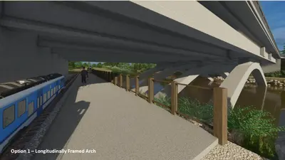
C-4 - Rehabilitation vs Replacement Memo – September 2022 City of Austin Barton Springs Road Bridge over Barton Creek Rehabilitation vs. Replacement Memorandum CIP ID 5873.031 URS Corporation 9400 Amberglen Blvd. Austin, TX 78729 (512) 419-5897 TX Firm F-3162 7650 W. Courtney Campbell Cswy. Tampa, FL 33607-1462 (813) 286-1711 September 28, 2022 Final (F1) This document is released under the authority of Robert B. Anderson Texas PE No. 111066 Barton Springs Road Bridge over Barton Creek Rehab vs. Replacement Memo REVISIONS Project: City of Austin – Barton Springs Road Bridge over Barton Creek Document: Rehab vs. Replacement Memo Revision Date of Issue Description D0 D1 D2 F1 08/22/2022 Draft Issue for Internal Comment 09/12/2022 Revised Draft Issue post PWD comments 09/19/2022 Revised Draft Issue cost table and replacement comparison 09/28/2022 Final Issue Contents 1. 2. 3. INTRODUCTION............................................................................................ 3 Purpose and Need .................................................................................. 3 1.1 Bridge Cultural / Historical Background / Existing Condition ......................... 3 1.2 DESIGN CONCEPTS ....................................................................................... 5 Design Elements Common to Both Rehabilitation and Replacement .............. 5 2.1 Rehabilitation Option .............................................................................. 5 2.2 Replacement Option ............................................................................... 7 2.3 COMPARISON OF PRELIMINARY REPLACEMENT / REHABILITATION CONCEPTS .................................................................................................. 10 4. SUMMARY AND RECOMMENDATIONS ......................................................... 12 Statement of Limitations This report is intended for the City of Austin and is distributed to third parties outside the City’s organization, with their consent. This interim memo provides a direct comparison between the rehabilitation and replacement options for the Barton Springs Road Bridge over Barton Creek and provides a recommendation from the design team. This report is intended to outline the current design approach and highlight the pros and cons associated with the rehabilitation and replacement concepts. To limit the size and focus of this memo, the detailed work associated with existing bridge inspection and preliminary concept development and analysis are incorporated by reference. Page 2 of 13 Barton Springs Road Bridge over Barton Creek Rehab vs. Replacement Memo 1. INTRODUCTION This section of the report summarizes the purpose and need for the project and provides some Cultural and Historical Background. 1.1 Purpose and Need The purpose and need for this project is centered on safety-related bridge improvements that address the following items: Insufficient bike / pedestrian paths (functionally obsolete); Age of structure / structural degradation; Bridge roadway lanes not aligned with lanes east of Azie Morton; Hillside instability (rock fall) and obsolete retaining wall on Azie Morton east side at intersection; Elevated / overhanging sidewalk integral to intersection – past movement / cracking; and Bridge / intersection congestion. 1.2 Bridge Cultural / Historical Background / Existing Condition The original Barton Springs Road bridge was built in 1925 and widened to its current configuration in 1945. The bridge is located adjacent to Zilker Park, which is listed in the National Register of Historic Places (NRHP); and is considered a contributing resource to the Park. The Barton Springs Archeological and Historical District (formed in 1985) is also located within the Zilker Historic District and the downstream boundary of this district is in close proximity to the bridge. The age of the south and north structures is 97 and 76 years, respectively. The bridge overall has a condition rating of "Fair," and most structural components generally have a condition rating of “Good”, based on the FHWA Condition Rating Guidelines. Given the advanced age of the deck, and the fact that the most serious deterioration is found within the vicinity of the longitudinal deck joint, it is necessary to replace the deck entirely and eliminate the longitudinal joint and transverse joints where practical. This precludes efforts to keep and repair all of the existing bridge components. In addition, the spandrel columns exhibit low concrete compressive strength and severe cracking, spalling, and/or delamination (2017 On-Site Sampling and Laboratory Investigation). The cracking of the shorter spandrel columns is further exacerbated by their structural configurations (moment connections at both the top and bottom), which attract an inordinately large amount of shear loading. Therefore, any proposed bridge rehabilitation strategy that provides a substantial increase in service life requires “stripping” the structure down to the arch ribs and reconstructing the spandrel columns, floor system, and deck. Sliding bearings at the tops of the new spandrel columns will decouple the deck from the supporting structure. Page 3 of 13 Barton Springs Road Bridge over Barton Creek Rehab vs. Replacement Memo Figure 1. Deterioration of Longitudinal Beam In addition to the condition of the existing bridge, the site presents a number of challenges and constraints. Many of these are illustrated in the issues map below: Figure 2. Barton Springs Rd. Bridge Challenges and Constraints Page 4 of 13 Barton Springs Road Bridge over Barton Creek Rehab vs. Replacement Memo 2. DESIGN CONCEPTS 2.1 Design Elements Common to Both Rehabilitation and Replacement Barton Springs Road serves as a vital roadway connector. Improvements include the realignment of the travel lanes to improve or eliminate the current offset movement at the Azie Morton Road interchange. The bridge provides a vital bicycle and pedestrian link to the Zilker Park and the existing bike/ pedestrian facilities are inadequate. The redesigned bridge provides dedicated bike lanes as well as a 14 ft. wide sidewalk on the south side of the bridge and an 18 ft. wide shared use path on the north side of the bridge. The design also links the sidewalks to the park trail system and accommodates the trails underneath the bridge. Lastly, the design will maintain space for the “Zilker Eagle” train that will be refurbished in the near future. Both the rehabilitation scheme and the replacement scheme share the same above- deck configuration, resulting in an overall bridge width increase from 59 ft. to 109 ft. Therefore, either approach will provide the same result with respect to traffic and bike/ pedestrian movements. Figure 3. Bridge and Roadway Proposed Geometric Plan 2.2 Rehabilitation Option The Rehabilitation Option will reuse portions of the existing bridge structure (with rehabilitation measures implemented) and widen each side to provide the ultimate width necessary for proposed multi-modal travel ways. Page 5 of 13 Barton Springs Road Bridge over Barton Creek Rehab vs. Replacement Memo Due to the deterioration of the existing bridge, only the existing arch ribs will remain. Figure 4. Bridge Rehabilitation – Remove Deck and Spandrel Columns; Remediate Remaining Structures Once the arches are exposed, work will include reinforcement of the existing abutments, repairs to the arches and installation of a cathodic protection system to reduce further deterioration of the steel rebar in the arch ribs. Four additional lines of arch ribs will be added to accommodate the wider deck above. Therefore, the existing arch ribs will only be visible when viewed from underneath the structure. Figure 5. Install New Arch Ribs, Spandrel Columns and Extend Abutments The fully rehabilitated bridge will maintain the overall appearance and configuration of the existing bridge, utilizing similar details for the arches, spandrel columns, longitudinal beams, etc. In accordance with current design practices, it is anticipated that the level of remediation and future corrosion mitigation methods will be employed to achieve an additional 50 to 75 years of bridge service life subsequent to the rehabilitation. Page 6 of 13 Barton Springs Road Bridge over Barton Creek Rehab vs. Replacement Memo While the rehabilitation option will provide the appearance of keeping the existing bridge, less than half of the original structure will remain intact and very little surficial materials will remain. Furthermore, very little of the original structure will be plainly visible after the new rib extensions on both sides and the installation of new spandrel columns and deck. As such, what will be predominantly in view is new bridge structure and materials. Figure 6. Rehabilitation Option Rendering 2.3 Replacement Option The Replacement Option will remove the existing bridge structure in its entirety and provide a new structure with the ultimate width necessary for proposed multi-modal travel ways. This option allows for lengthening the bridge by moving the western abutment to the west. In so doing, the Replacement Option provides additional space to facilitate improvements to existing Zilker Park facilities, such as walking paths and the Zilker Eagle miniature railroad, both of which pass under the Barton Springs Road Bridge on the west bank. This additional space for improvements is not feasible with the Rehabilitation Option. A number of design options for the replacement bridge were developed and vetted with the City of Austin and various stakeholders. Table 2-1 provides a summary of the comparison of rehabilitation options. Page 7 of 13 Barton Springs Road Bridge over Barton Creek Rehab vs. Replacement Memo historic impact avoidance and historic impact minimization are simply not possible. Therefore, the focus of the investigation has centered on the development of feasible restoration and replacement schemes that meet the current transportation demands while providing a structure with a lifespan of at least 75 additional years of service. Both rehabilitation and replacement can accommodate the transportation needs in a similar fashion. The replacement scheme offers numerous additional benefits (highlighted cells in the above table) including better accommodations of the Zilker Eagle mini-train and enhanced trails underneath the bridge. The most significant differences between the rehabilitation scheme and the replacement scheme are cost and risk. The particular replacement bridge alternative selected is not the least expensive design possible, it includes enhanced features such as unique piers and upgraded abutments. Even with these enhancements, the cost of the replacement bridge is 40% less than the rehabilitation scheme. Furthermore, ongoing maintenance cost and labor requirements are less with the replacement scheme. There is also a great deal of risk associated with the rehabilitation scheme. While the bridge condition survey was thorough, there are many things that could increase the cost of rehabilitation once the initial demolition exposes all of the “hidden” elements of the bridge. We understand the significance of the existing bridge and the importance of preserving historical assets. However, as stewards of the taxpayer’s money there is an obligation to make the best value decision for the community. If the bridge is rehabilitated, very little of the existing structure will remain and those remaining elements will be almost entirely concealed by the new construction. This fact coupled with the significant increase in cost and risk leads the design team to recommend replacement as the path forward. The project is continuing an on-going coordination with the Texas Historical Commission (THC); and it is intended that input from both the THC and U.S. Army Corps of Engineers will be forthcoming as coordination continues. Page 13 of 13 C-5 - MMA Memo City Staff to Council – Nov. 2022 2016 inspection of the bridge, the minor rehabilitation option was removed from consideration, leaving one major rehabilitation option and three replacement options. All four remaining alternatives were considered using design concepts that were developed to accommodate bridge roadway, pedestrian, and bike users. These design concepts were vetted with various City Departments including significant input from the Austin Transportation Department. Additional input for design concepts included accommodating traffic during construction, existing and future hike/bike trail elements, as well as hillside instability issues along the nearby Umlauf property. The result is that all four alternatives would include at least: A bridge widened on both sides to keep the current four traffic lanes; Two new 10 ft. bike lanes; Pedestrian paths of 14 ft. and 18 ft. on the north and south side, respectively. Rehabilitation Alternative The lone rehabilitation option includes removal of deck, substructure, and columns, and leaving only the arch ribs. The existing arch ribs and abutments will require repair/resurfacing and installation of a cathodic protection system to reduce further deterioration. Four additional lines of arch ribs will be added to accommodate the wider deck above. While the rehabilitation option will provide the appearance of keeping the existing bridge, much less than half of the original structure will remain intact and very little surficial materials will remain; furthermore, the new arch ribs will essentially block the historic/existing arch ribs from exterior view. Replacement Alternatives Three alternatives were developed and compared in cost, aesthetics, constructability, and visual perspective from trails, sidewalks, parkland, and the creek. Please see Table 2.1 below for details. The preferred alternative for replacement shown below maximizes views through the bridge and maintains an open center channel in Barton Creek. This is also the most cost-effective alternative. Preferred Replacement Alternative This preferred Replacement Alternative was specifically compared to the Rehabilitation Alternative, with respect to various features and components, such as roadway alignment, accommodation of hike/bike trails, Barton Creek impacts, cost, maintenance requirements, constructability, and risk. A table of these factors is presented in the attached document. The Replacement option offers numerous benefits over the Rehabilitation option, including better accommodations of the Zilker Eagle mini-train, enhanced trails underneath the bridge, and others highlighted in the more detailed design summary. The most significant differences between the rehabilitation scheme and the replacement scheme are cost and risk. The cost of the replacement option is 40% less than the rehabilitation option, and more risk is inherent in the rehabilitation scheme, due to the reliance on existing structural members whose true capacity can only be revealed through the subsequent design and construction process. Recommendation: Move Forward to Update Community on Replacement Alternative Based on the information outlined above and within the attached, staff recommends replacement of the existing bridge as the preferred alternative moving forward. Replacement offers the best choice based on value, historical preservation, and being a long term transportation solution for the community. cc: Spencer Cronk, City Manager Gina Fiandaca, Assistant City Manager Attachment: Memo from Consultant re: Rehabilitation and Replacement Options for Bridge of Barton Creek City of Austin Barton Springs Road Bridge over Barton Creek Rehabilitation vs. Replacement Memorandum CIP ID 5873.031 URS Corporation 9400 Amberglen Blvd. Austin, TX 78729 (512) 419-5897 TX Firm F-3162 7650 W. Courtney Campbell Cswy. Tampa, FL 33607-1462 (813) 286-1711 September 28, 2022 Final (F1) This document is released under the authority of Robert B. Anderson Texas PE No. 111066 Barton Springs Road Bridge over Barton Creek Rehab vs. Replacement Memo REVISIONS Project: City of Austin – Barton Springs Road Bridge over Barton Creek Document: Rehab vs. Replacement Memo Revision Date of Issue Description D0 D1 D2 F1 08/22/2022 Draft Issue for Internal Comment 09/12/2022 Revised Draft Issue post PWD comments 09/19/2022 Revised Draft Issue cost table and replacement comparison 09/28/2022 Final Issue Contents 1. 2. 3. INTRODUCTION............................................................................................ 3 Purpose and Need .................................................................................. 3 1.1 Bridge Cultural / Historical Background / Existing Condition ......................... 3 1.2 DESIGN CONCEPTS ....................................................................................... 5 Design Elements Common to Both Rehabilitation and Replacement .............. 5 2.1 Rehabilitation Option .............................................................................. 5 2.2 Replacement Option ............................................................................... 7 2.3 COMPARISON OF PRELIMINARY REPLACEMENT / REHABILITATION CONCEPTS .................................................................................................. 10 4. SUMMARY AND RECOMMENDATIONS ......................................................... 12 Statement of Limitations This report is intended for the City of Austin and is distributed to third parties outside the City’s organization, with their consent. This interim memo provides a direct comparison between the rehabilitation and replacement options for the Barton Springs Road Bridge over Barton Creek and provides a recommendation from the design team. This report is intended to outline the current design approach and highlight the pros and cons associated with the rehabilitation and replacement concepts. To limit the size and focus of this memo, the detailed work associated with existing bridge inspection and preliminary concept development and analysis are incorporated by reference. Page 2 of 13 Barton Springs Road Bridge over Barton Creek Rehab vs. Replacement Memo 1. INTRODUCTION This section of the report summarizes the purpose and need for the project and provides some Cultural and Historical Background. 1.1 Purpose and Need The purpose and need for this project is centered on safety-related bridge improvements that address the following items: Insufficient bike / pedestrian paths (functionally obsolete); Age of structure / structural degradation; Bridge roadway lanes not aligned with lanes east of Azie Morton; Hillside instability (rock fall) and obsolete retaining wall on Azie Morton east side at intersection; Elevated / overhanging sidewalk integral to intersection – past movement / cracking; and Bridge / intersection congestion. 1.2 Bridge Cultural / Historical Background / Existing Condition The original Barton Springs Road bridge was built in 1925 and widened to its current configuration in 1945. The bridge is located adjacent to Zilker Park, which is listed in the National Register of Historic Places (NRHP); and is considered a contributing resource to the Park. The Barton Springs Archeological and Historical District (formed in 1985) is also located within the Zilker Historic District and the downstream boundary of this district is in close proximity to the bridge. The age of the south and north structures is 97 and 76 years, respectively. The bridge overall has a condition rating of "Fair," and most structural components generally have a condition rating of “Good”, based on the FHWA Condition Rating Guidelines. Given the advanced age of the deck, and the fact that the most serious deterioration is found within the vicinity of the longitudinal deck joint, it is necessary to replace the deck entirely and eliminate the longitudinal joint and transverse joints where practical. This precludes efforts to keep and repair all of the existing bridge components. In addition, the spandrel columns exhibit low concrete compressive strength and severe cracking, spalling, and/or delamination (2017 On-Site Sampling and Laboratory Investigation). The cracking of the shorter spandrel columns is further exacerbated by their structural configurations (moment connections at both the top and bottom), which attract an inordinately large amount of shear loading. Therefore, any proposed bridge rehabilitation strategy that provides a substantial increase in service life requires “stripping” the structure down to the arch ribs and reconstructing the spandrel columns, floor system, and deck. Sliding bearings at the tops of the new spandrel columns will decouple the deck from the supporting structure. Page 3 of 13 Barton Springs Road Bridge over Barton Creek Rehab vs. Replacement Memo Figure 1. Deterioration of Longitudinal Beam In addition to the condition of the existing bridge, the site presents a number of challenges and constraints. Many of these are illustrated in the issues map below: Figure 2. Barton Springs Rd. Bridge Challenges and Constraints Page 4 of 13 Barton Springs Road Bridge over Barton Creek Rehab vs. Replacement Memo 2. DESIGN CONCEPTS 2.1 Design Elements Common to Both Rehabilitation and Replacement Barton Springs Road serves as a vital roadway connector. Improvements include the realignment of the travel lanes to improve or eliminate the current offset movement at the Azie Morton Road interchange. The bridge provides a vital bicycle and pedestrian link to the Zilker Park and the existing bike/ pedestrian facilities are inadequate. The redesigned bridge provides dedicated bike lanes as well as a 14 ft. wide sidewalk on the south side of the bridge and an 18 ft. wide shared use path on the north side of the bridge. The design also links the sidewalks to the park trail system and accommodates the trails underneath the bridge. Lastly, the design will maintain space for the “Zilker Eagle” train that will be refurbished in the near future. Both the rehabilitation scheme and the replacement scheme share the same above- deck configuration, resulting in an overall bridge width increase from 59 ft. to 109 ft. Therefore, either approach will provide the same result with respect to traffic and bike/ pedestrian movements. Figure 3. Bridge and Roadway Proposed Geometric Plan 2.2 Rehabilitation Option The Rehabilitation Option will reuse portions of the existing bridge structure (with rehabilitation measures implemented) and widen each side to provide the ultimate width necessary for proposed multi-modal travel ways. Page 5 of 13 Barton Springs Road Bridge over Barton Creek Rehab vs. Replacement Memo Due to the deterioration of the existing bridge, only the existing arch ribs will remain. Figure 4. Bridge Rehabilitation – Remove Deck and Spandrel Columns; Remediate Remaining Structures Once the arches are exposed, work will include reinforcement of the existing abutments, repairs to the arches and installation of a cathodic protection system to reduce further deterioration of the steel rebar in the arch ribs. Four additional lines of arch ribs will be added to accommodate the wider deck above. Therefore, the existing arch ribs will only be visible when viewed from underneath the structure. Figure 5. Install New Arch Ribs, Spandrel Columns and Extend Abutments The fully rehabilitated bridge will maintain the overall appearance and configuration of the existing bridge, utilizing similar details for the arches, spandrel columns, longitudinal beams, etc. In accordance with current design practices, it is anticipated that the level of remediation and future corrosion mitigation methods will be employed to achieve an additional 50 to 75 years of bridge service life subsequent to the rehabilitation. Page 6 of 13 Barton Springs Road Bridge over Barton Creek Rehab vs. Replacement Memo While the rehabilitation option will provide the appearance of keeping the existing bridge, less than half of the original structure will remain intact and very little surficial materials will remain. Furthermore, very little of the original structure will be plainly visible after the new rib extensions on both sides and the installation of new spandrel columns and deck. As such, what will be predominantly in view is new bridge structure and materials. Figure 6. Rehabilitation Option Rendering 2.3 Replacement Option The Replacement Option will remove the existing bridge structure in its entirety and provide a new structure with the ultimate width necessary for proposed multi-modal travel ways. This option allows for lengthening the bridge by moving the western abutment to the west. In so doing, the Replacement Option provides additional space to facilitate improvements to existing Zilker Park facilities, such as walking paths and the Zilker Eagle miniature railroad, both of which pass under the Barton Springs Road Bridge on the west bank. This additional space for improvements is not feasible with the Rehabilitation Option. A number of design options for the replacement bridge were developed and vetted with the City of Austin and various stakeholders. Table 2-1 provides a summary of the comparison of rehabilitation options. Page 7 of 13 Barton Springs Road Bridge over Barton Creek Rehab vs. Replacement Memo historic impact avoidance and historic impact minimization are simply not possible. Therefore, the focus of the investigation has centered on the development of feasible restoration and replacement schemes that meet the current transportation demands while providing a structure with a lifespan of at least 75 additional years of service. Both rehabilitation and replacement can accommodate the transportation needs in a similar fashion. The replacement scheme offers numerous additional benefits (highlighted cells in the above table) including better accommodations of the Zilker Eagle mini-train and enhanced trails underneath the bridge. The most significant differences between the rehabilitation scheme and the replacement scheme are cost and risk. The particular replacement bridge alternative selected is not the least expensive design possible, it includes enhanced features such as unique piers and upgraded abutments. Even with these enhancements, the cost of the replacement bridge is 40% less than the rehabilitation scheme. Furthermore, ongoing maintenance cost and labor requirements are less with the replacement scheme. There is also a great deal of risk associated with the rehabilitation scheme. While the bridge condition survey was thorough, there are many things that could increase the cost of rehabilitation once the initial demolition exposes all of the “hidden” elements of the bridge. We understand the significance of the existing bridge and the importance of preserving historical assets. However, as stewards of the taxpayer’s money there is an obligation to make the best value decision for the community. If the bridge is rehabilitated, very little of the existing structure will remain and those remaining elements will be almost entirely concealed by the new construction. This fact coupled with the significant increase in cost and risk leads the design team to recommend replacement as the path forward. The project is continuing an on-going coordination with the Texas Historical Commission (THC); and it is intended that input from both the THC and U.S. Army Corps of Engineers will be forthcoming as coordination continues. Page 13 of 13 C-6 – Bridge Alternative Cost Estimates C-7 – Geotechnical Data Report GEOTECHNICAL DATA REPORT BARTON SPRINGS ROAD BRIDGE AND ROADWAY IMPROVEMENTS CIP ID NO. 5873.031 AUSTIN, TEXAS AECOM Austin, Texas Mr. Darrell Jones, PE AECOM 9400 Amberglen Blvd, Bldg E Austin, Texas 78729 Job No. 0121-014 August 10, 2023 Geotechnical Data Report Barton Springs Road Bridge and Roadway Improvements CIP ID No. 5873.031 Austin, Texas Submitted herewith is the Geotechnical Data Report (GDR) for the above referenced project. In brief, this report presents the results of the field investigation, laboratory testing, and discussion of area geology, site and subsurface conditions based on geotechnical data collected for this project. The findings and recommendations for this study are being submitted in a multi-report format consisting of a Geotechnical Data Report (GDR) presented herein, and Geotechnical Design Memoranda (GDM) to provide geotechnical recommendations for the bridge, retaining walls, and pavement design. The GDM will be submitted under separate cover, and as design progresses. Balcones Geotechnical, LLC (Balcones) appreciates the opportunity to provide these geotechnical services to the project team and looks forward to our continued association throughout final design and construction phases. Sincerely, BALCONES GEOTECHNICAL, LLC TBPE Firm Registration No. F-15624 Russell D. Sieg, P.E. Geotechnical Engineer Rebecca A. Russo, P.E. Senior Geotechnical Engineer CONTENTS PAGE INTRODUCTION ........................................................................................................................ 1 AUTHORIZATION AND SCOPE ................................................................................................. 2 FIELD INVESTIGATION ............................................................................................................. 2 LABORATORY INVESTIGATION ............................................................................................... 5 Soil and Rock Testing ...................................................................................................... 5 Advanced Lab Testing ..................................................................................................... 5 Analytical Testing ............................................................................................................ 8 SITE AND SUBSURFACE CONDITIONS ................................................................................... 8 Physiography ................................................................................................................... 8 Geology ......................................................................................................................... 10 Stratigraphy and Engineering Properties ....................................................................... 12 Groundwater.................................................................................................................. 14 CONDITIONS ........................................................................................................................... 15 LIST OF TABLES Table 1 – Boring Summary......................................................................................................... 3 Table 2 – Pressure Swell Test Results ....................................................................................... 6 Table 3 – Direct Shear Test Results ........................................................................................... 6 Table 4 – CU Triaxial w/ Pore-Pressure Test Results (Remolded) ............................................. 7 Table 5 – Analytical Test Results ............................................................................................... 8 Table 6 – Engineering Properties – Bridge / Structure Borings ..................................................12 Table 7 – Engineering Properties – Retaining Wall Borings ......................................................13 Table 8 – Existing Pavement Thickness ....................................................................................14 Table 9 – Groundwater Summary .............................................................................................14 -i- FIGURES PLATE VICINITY MAP ............................................................................................................................ 1 BORING LOCATION PLAN ........................................................................................................ 2 GENERALIZED SUBSURFACE PROFILE ................................................................................. 3 USGS TOPOGRAPHIC MAP ...................................................................................................... 4 GEOLOGIC MAP ........................................................................................................................ 5 STRATIGRAPHIC COLUMN OF THE AUSTIN AREA ................................................................ 6 APPENDICES BORING LOGS AND CORE PHOTOGRAPHS ....................................................... APPENDIX A LABORATORY TEST RESULTS ............................................................................ APPENDIX B -ii- INTRODUCTION The project will include bridge and roadway improvements to the existing Barton Springs Road bridge over Barton Creek, in Austin, Texas. The project site is located at the intersection of Barton Springs Road and Azie Morton Road, as shown on the Vicinity Map, Plate 1. Proposed project components will include: Widening and/or replacement of the existing Barton Springs Rd Bridge over Barton Creek with pedestrian access improvements. Adding a turn lane at Azie Morton Road with construction of retaining walls and stabilizing the hillside slope. Stream bank improvements and stabilization along Barton Creek at the bridge abutments and nearby pedestrian trail. Selected site photographs of the bridge and existing retaining wall are below. Photo 1 (2/18/2022) – Barton Springs Rd Photo 2 (2/18/2022) – Azie Morton Rd Retaining Bridge over Barton Creek, facing east Wall, facing north A Preliminary Geotechnical issued by Arias Geoprofessionals, dated March 20, 2018. The previous scope of work included drilling 3 borings and providing preliminary foundation recommendations for use in evaluating design alternatives for bridge improvement being considered at the time. Boring and laboratory data performed for that previous study are included in this report. Investigation and Report was The following sections of this report include a discussion of authorization and scope; field and laboratory investigation procedures; and area geology, site and subsurface conditions. Geotechnical recommendations for the proposed improvements are being submitted under separate cover in a Geotechnical Design Memorandum (GDM) format. -1- AUTHORIZATION AND SCOPE The geotechnical investigation was authorized by AECOM with issuance of Purchase Order No. 140460 dated January 11, 2022. The contract includes Attachment 1 which outlines the authorized and agreed upon scope of services. The scope of the investigation included: 1) drilling 10 borings to determine subsurface conditions along the project alignment and for obtaining representative samples for laboratory testing; 2) laboratory testing to determine classification and index properties of site soils and rock, and 3) preparation of this Geotechnical Data Report (GDR). Geotechnical Design Memoranda (GDM) will be submitted under separate cover to provide geotechnical recommendations for bridge foundations, retaining walls and slope stabilization, and for pavements. Field sampling and laboratory testing were conducted in general accordance with methods, procedures, and practices set forth by the American Society for Testing and Materials, latest version of Annual Book of ASTM Standards, where applicable. FIELD INVESTIGATION The field investigation consisted of drilling ten (10) borings, designated T-1 through T-5 for borings drilled along the pedestrian trail, and W-1 through W-5 for borings drilled along the proposed roadway retaining wall along Azie Morton Road. Approximate boring locations are shown on the Plan of Borings, presented on Plate 2. The T-borings were drilled to depths of 40 to 60 ft below existing grade, and the W-borings were drilled to depths of 50 to 110 ft below existing grade. As mentioned previously, borings have been drilled in the vicinity of this project by Arias1, and by Fugro2. The applicable borings are included in this report. A summary of boring drilling information is presented in the following Table 1. Ground surface elevations (GSE) shown in the table and on the boring logs were estimated from the 1-ft contour ground surface information provided by the project team, and should be considered approximate. Latitude and Longitude GPS coordinates were obtained at the boring locations using a hand-held GPS device and should also be considered approximate. 1 2 Geotechnical Investigation, Barton Springs Road Bridge Improvement Project, for AECOM by Arias Geoprofessionals, Report No. 2015-762 (March 20, 2018). Geotechnical Investigation, Barton Springs Road Improvements, for City of Austin by Fugro South, Inc., Report No. 1001-2559 (June 14, 1999). -2- Photo 3 (4/19/2022) – Drilling W-3 Photo 4 (5/3/2022) – Drilling W-5 Detailed descriptions of subsurface materials encountered at the boring locations are presented on the Logs of Borings included in Appendix A. Photographs of rock core samples for the borings are also included in Appendix A, following the respective boring log. Keys to Terms and Symbols used on the logs are also set forth in Appendix A following the boring logs. A Generalized Subsurface Profile for the project borings is provided on Plate 3. Pocket penetrometer values in tons per square foot, and Standard Penetration Test N-values in blows per foot, and Core Recovery and Rock Quality Designation (RQD) values in percent (ASTM D6032), are shown on the logs of borings at the respective test depth. Groundwater and/or drilling fluid observations made during drilling are presented on the boring logs. Borings were backfilled with a mixture of auger cuttings and bentonite upon completion of drilling. Borings drilled in grassed areas were accessed using mats to protect vegetation and mature tree root zones, and included erosion control measure to control migration of sediment and fluids during drilling. Drilling spoils were drummed and disposed of off site. Photo 5 (4/5/2022) – Mobilizing to T-2 Photo 6 (4/8/2022) – Demobilizing from T-1 -4- LABORATORY INVESTIGATION The laboratory testing program included classification and strength testing of soil and rock strata encountered in the borings. The testing included standard soil index and rock strength testing, advanced laboratory testing consisting of consolidated-undrained triaxial, direct shear, and pressure swell testing; and analytical testing. Results are presented in Appendix B and summarized in the following sections. Detailed descriptions of the test procedures are included in Appendix B, preceding the laboratory data. Soil and Rock Testing Soil classification tests, including Atterberg limit determinations (ASTM D4318), partial grain-size analyses (ASTM D422), and moisture content (ASTM D2216), were conducted on representative samples of the soil strata. Unconfined compression (UC) (ASTM D7012) and unconsolidated-undrained triaxial compression (UU) (ASTM D2850) testing was conducted on representative samples of limestone and clayshale, respectively, to evaluate the compressive strength of the subsurface strata. The results of these tests are tabulated on the boring logs at the sample recovery depths. Test results are presented in the Summary of Laboratory testing table included in Appendix B. Grain size curves are presented in Appendix B-1. Advanced Lab Testing Advanced testing was performed on representative samples of clay, clayshale and limestone to characterize undrained and drained shear strengths for global stability analyses of the proposed retaining wall system. The test samples were selected by Balcones and testing was performed by TRI Environmental. The advanced testing included: Pressure Swell (ASTM D4546) Direct Shear (ASTM D3080) Consolidated Undrained (CU) Triaxial Compression with pore-pressure measurements (ASTM D4767) (remolded samples) Individual test results are in Appendices B-2 through B-4 and are summarized in the following subsections, which include a brief description of the test procedure. -5- Azie Morton Road. The improvements along Azie Morton Road will consist of a retaining wall to replace an existing timber tie wall along the east side of the roadway intersection near Barton Springs Road. The slope is approximately 40 ft tall, and includes structures at the top of the slope associated with the Umlauf Sculpture Garden and Museum. The retaining wall will also serve to keep boulders present at the top of the slope from falling onto Azie Morton Road. Slope improvements may also be required along the west side of Azie Morton Road along the boundary with the Pedestrian Trail and Barton Creek. Ground surface elevations along this portion of the project generally range from about El. 462 ft along the roadway to about El. 435 ft along the pedestrian trail along the bank of Barton Creek. West Bridge Approach. The west bridge approach is relatively flat with approximate ground surface elevations of El. 455 to 460 ft, with lower elevations near the creekbank. Pedestrian amenities, including a small pedestrian train known as Zilker Eagle, and associated track are located along the west bridge approach, extending beneath the existing bridge roadway. Photographs of the small train and track near boring T-2 are below. Photos 7,8 (4/5/2022) – Zilker Eagle Train (small pedestrian train) and track beneath west bridge approach, near the boring T-2 location Pedestrian Trail. The site conditions along the existing Barton Creek banks include an active pedestrian trail. Some portions of the trail along the east bank (west side of Azie Morton Road) are eroded, and include some structurally suspended components. The same is true along the west side of the creek. Selected site photographs of the trail along the east and west banks are shown on the following page. -9- Photo 9 (2/18/2022) – Pedestrian Trail beneath Photo 10 (2/18/2022) – Pedestrian Trail beneath east bridge abutment, facing north west bridge abutment, facing north Geology According to published geologic mapping3 and area boring data, the project alignment is mapped as being underlain by alluvium and Lower Colorado River and Tributary terrace deposits, further underlain by Del Rio Clay and Clayshale and Georgetown Limestone. Buda Limestone is also mapped at the upper elevations of the project site. A Geologic Map is presented on Plate 5. A Stratigraphic Column of the Austin Area4 is presented on Plate 6. A brief description of the geologic formations encountered in this investigation, in order of youngest to oldest, is provided in the following subsections. Alluvium, Terrace Deposits. Alluvium (Qal) and Terrace Deposits (Qlcr, Lower Colorado River; Qucr, Upper Colorado River; Qtt Terrace deposits) are sediments deposited by flowing water, likely the Colorado River and Barton Creek. The alluvium (Qal) is relatively more recent Holocene-era, while the Terrace deposits (Qlcr, Qucr, Qtt) are relatively older Pleistocene-era, both of the Quaternary epoch. The deposits consist of various proportions of clay, silt, sand, and gravel, which typically coarsen in grainsize with depth. Some cobbles or boulders may be present in the lower portions of the Terrace deposits, associated with larger water bodies and more energy to carry large sediments. Sand and gravel lenses and layers, and cobbles, may be present at erratic locations 3 4 Garner, L.E. and Young, K.P. (1976), “Environmental Geology of the Austin Area: An Aid to Urban Planning,” Report of Investigation No. 86, Bureau of Economic Geology, The University of Texas at Austin, Plate VII (reprinted 1992). Garner, L.E., “Environmental Geology of the Austin Area,” M.A. Thesis, The University of Texas at Austin (1973). -10- within the fine-grained strata due to the depositional nature of alluvium. The contact with the underlying bedrock is erosional in nature and can vary by several feet in short distances. It should be noted that, in general, it is difficult to discern the younger alluvial soils from older terrace deposits due to the similarity in composition and origin. Accordingly, no distinction was made on the boring logs regarding alluvium or terrace deposits and the stratum is referred to as alluvium. Buda Formation. The Buda formation (Kbu) consists of an upper hard, resistant, fine grained, burrowed, glauconitic, shell-fragment limestone and a lower marly, nodular, and less resistant limestone. The Buda limestone is colored with shades of tan to orange-brown that resemble discoloration caused by heating. The Buda limestone is typically 35 to 40 ft thick in the downtown Austin area. Del Rio Formation. The Del Rio formation (Kdr), when unweathered, is composed mostly of dark olive gray, greenish gray, to bluish gray, pyritic, selenitic, gypsiferous clayshale often with a few thin siltstone or sandstone beds near the top. The ram’s horn oyster Exogyra Arietina, characteristic of the Del Rio formation and particularly abundant in the lower part, is the index fossil. The formation is commonly very stiff to hard, calcareous and occasionally thinly laminated. The Del Rio/Georgetown contact is abrupt at some locations and transitional in others with a transition zone of shaly limestones. With weathering, the Del Rio becomes tan and fissured. During the weathering process, large quantities of the illite clay mineral alter to montmorillonite, thereby significantly increasing the swelling potential. The Del Rio clay and clayshale is a much weaker formation than the overlying Buda, and is highly plastic with a very high shrink/swell potential if subjected to moisture changes. The Del Rio Clay and Clayshale formation is on the order of 70 ft thick in the Austin area. Georgetown Formation. The Georgetown formation (Kgt) consists of thin interbeds of gray to tan, richly fossiliferous, nodular, fine-grained, limestone and shaly limestone. The thickness of the unit in the Austin area is generally about 55 ft but varies from 40 to 60 ft. Small quantities of naturally occurring liquid and tarry hydrocarbons are found throughout the formation. The Edwards limestone formation (Ked) underlies the Georgetown limestone; however, the borings did not encounter Edwards limestone. Surface outcropping of Edwards limestone is mapped in the vicinity of the project site. -11- For the borings drilled in the Barton Creek floodplain, groundwater will likely be present in the upper Alluvium or Del Rio clay soil strata, perched atop the underlying less pervious Del Rio clayshale and Georgetown limestone. For borings W-2 through W-5, groundwater was not encountered before wet rotary coring was initiated in the borings. Groundwater may have been present but not detected during drilling. Groundwater conditions are based on antecedent rainfall conditions and proximity to surface waters (Barton Creek) and may be different at the time of construction. Excavations through alluvial soils can expect to encounter groundwater at approximate elevation El. 430± ft or higher due to the normal pool maintained at Barton Creek. CONDITIONS Since some variation was found in subsurface conditions at boring locations, all parties involved should take notice that even more variation may be encountered between boring locations. Statements in the report as to subsurface variation over given areas are intended only as estimations from the data obtained at specific boring locations. The professional services that form the basis for this report have been performed using that degree of care and skill ordinarily exercised, under similar circumstances, by reputable geotechnical engineers practicing in the same locality. No other warranty, expressed or implied, is made as the professional advice set forth. The results contained in this report are directed at, and intended to be utilized within, the scope of work contained in the agreement executed by Balcones Geotechnical, LLC and client. This report is not intended to be used for any other purposes. * * * -15- PLATES APPENDIX A – BORING LOGS APPENDIX A-1 (Current Study) Boring Logs and Core Photographs Keys to Terms and Symbols Project No. 0121-014 16.5 ft 0 ft 6 ft 20 ft 30 ft 36.5 ft SAMPLE PHOTOGRAPHS – T-1 Barton Springs Road Bridge Improvements Austin, Texas Sheet 1 of 2 40 ft – Georgetown Limestone Project No. 0121-014 50 ft 45 ft 55 ft 50 ft 60 ft SAMPLE PHOTOGRAPHS – T-1 Barton Springs Road Bridge Improvements Austin, Texas Sheet 2 of 2 0 ft 9 ft 25 ft SAMPLE PHOTOGRAPHS – T-2 Barton Springs Road Bridge Improvements Austin, Texas Project No. 0121-014 8.5 ft 31 ft Sheet 1 of 3 35 ft – Georgetown Limestone Project No. 0121-014 40 ft 45 ft 45 ft 55 ft 50 ft SAMPLE PHOTOGRAPHS – T-2 Barton Springs Road Bridge Improvements Austin, Texas Sheet 2 of 3 55 ft Project No. 0121-014 60 ft SAMPLE PHOTOGRAPHS – T-2 Barton Springs Road Bridge Improvements Austin, Texas Sheet 3 of 3 Project No. 0121-014 9.5 ft 0 ft 6 ft 15 ft 30 ft 36.5 ft SAMPLE PHOTOGRAPHS – T-3 Barton Springs Road Bridge Improvements Austin, Texas Sheet 1 of 3 36 ft Georgetown Limestone Project No. 0121-014 40 ft 45 ft 45 ft 50 ft SAMPLE PHOTOGRAPHS – T-3 Barton Springs Road Bridge Improvements Austin, Texas 55 ft Sheet 2 of 3 55 ft Project No. 0121-014 60 ft SAMPLE PHOTOGRAPHS – T-3 Barton Springs Road Bridge Improvements Austin, Texas Sheet 3 of 3 Project No. 0121-014 15 ft 0 ft 8 ft 15 ft – Georgetown Limestone 20 ft SAMPLE PHOTOGRAPHS – T-4 Barton Springs Road Bridge Improvements Austin, Texas 25 ft Sheet 1 of 2 25 ft 35 ft Project No. 0121-014 35 ft 30 ft 40 ft SAMPLE PHOTOGRAPHS – T-4 Barton Springs Road Bridge Improvements Austin, Texas Sheet 2 of 2 Project No. 0121-014 2 ft 7.5 ft 15 ft – Georgetown Limestone 15 ft 20 ft SAMPLE PHOTOGRAPHS – T-5 Barton Springs Road Bridge Improvements Austin, Texas 25 ft Sheet 1 of 2 25 ft 35 ft Project No. 0121-014 30 ft 35 ft 40 ft SAMPLE PHOTOGRAPHS – T-5 Barton Springs Road Bridge Improvements Austin, Texas Sheet 2 of 2