05.1 - 1504 E 11th St - Drawings & Photos — original pdf
Backup
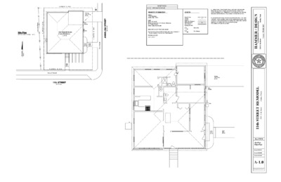
S 67D02'19" E 47.00' One Story Brick and Frame Residence (1,377 sf) PP ' 0 0 . 0 6 W ' " 0 0 7 3 D 3 2 S Existing Conc. Drive (92 sf) E Elec. Service Gas Conc. Porch (63 sf) Conc. Walk (26 sf) Site Plan 1/8"=1'-0" (1/16" = 1'-0" for 11"x17") E x i s t i n g W o o d F e n c e ' 0 0 . 0 6 E ' " 0 0 7 3 D 3 2 N AC d e m u s s A h t r o N Conc. Walk (65 sf) N 67D02'19" W 47.00' Existing 4' Sidewalk 11th STREET (60' R.O.W.) T E E R T S A N L E G N A I ) . . W O R . ' 0 5 ( SHEET INDEX A-1.0 SITE PLAN / FLOOR PLAN PROJECT INFORMATION LEGEND Address: 1504 E 11th Street Austin, Texas. 78702 Legal: Zoned- SF-3-H-NP Being a portion of lots 5 & 6. Rectors Subdivision Vol. 1; Page 45 of the Travis County Deed Records DESCRIPTION OF PROPOSED WORK Extensive interior remodel while maintaining the historic character of 11th street elevation. 2 bedroom and 2 bath proposed. EXISTING LOT SIZE Lot = 2,820 s.f. Property Line Fencing Setback Public Util. Easement Electrical Service New Addition Existing Structure PP FH Power Pole Fire Hydrant a. Smoke Alarms: Provide Smoke Alarms - hard wired, interconnected, battery backup, at each sleeping room and immediate common area outside of sleeping rooms. If applicable, on each additional story including basements and habitable attics. In accordance with 2021 IRC Sec R314. X E b. Carbon Monoxide Alarms: Provide Carbon Monoxide Alarm - hard wired with battery backup, installed outside of each separate sleeping area in the immediate vicinity of the bedrooms in dwelling units within which fuel-fired appliances are installed and/or have an attached garage. In accordance with 2021 IRC sec R315" l k a w e d S i i . t s x E -6" WH AC Existing Conc. Drive (92 sf) Elec. Service Gas Conc. Porch (63 sf) Conc. Walk (26 sf) N G I S E D / R E M M A H p i h s r e n t r a p n o i t c u r t s n o c & e r u t c e t i h c r a l a i t n e d i s e r A s a x e T , n i t s u A t e e r t S h t 5 . S 8 0 2 3 2 6 6 2 - 6 2 6 - 2 1 5 : t c a t n o C Seal s a x e T , n i t s u A t e e r t S h t 1 1 4 0 5 1 L E D O M E R T E E R T S h t 1 1 Date: 07/07/25 Site Plan- Floor Plan- Revised: 00/00/25 Revised: 00/00/00 Revised: 00/00/00 A-1.0 These Drawings are the property of the Architect and may only be used in connection with this project. 10'-10 1/4" 48" x 36"H Slider AC 48" x 36"H Slider Master Bath Bidet " 8 - ' 4 Pantry 5' Pocket Pair Wardrobe Broom Ref. Kitchen Raise Floor e c i v r e S . c e E l r e d i l S ' 5 Tools 6'-0" r i a P t e k c o P ' 5 Mud Rm. W D 72" x 12" H Fixed Master Bed King 30" Pocket Walk-in Closet Archway " 8 - ' 6 " 8 / 5 8 - ' 3 1 14'-4 1/2" Shoes s t e n b a C i . t g H l l u F i g n n D i Existing Conc. Drive (92 sf) " 2 / 1 1 1 - ' 3 1 Gas " 8 / 3 3 - ' 1 1 Scheme 3.2 1/4"=1'-0" Egress 30"x 78"H DH " 2 - ' 5 36"x18" Awning i e n L e c n e F / i e n L y t r e p o r P 30" Pocket Bath Lin. 32" Pocket Hall 32" Pocket e b o r d r a W Coat 36" Pull-down Ladder Archway Entry 6'-7" 36" w/ Sidelight Archway 30" 12'-8 7/8" Conc. Porch (63 sf) TV " 2 - ' 5 1 Living Conc. Walk (26 sf) Awning to Remian 30"x 76"H Casement 30"x 78"H DH Daybed " 0 - ' 1 1 13'-8 1/2" Office/ Bedroom Egress 30"x 78"H DH Desk Replace Existing with New Fixed Windows New Concrete Landing 5'-0" " 0 - ' 3 Replace Existing with New Fixed Windows N G I S E D p i h s r e n t r a p n o i t c u r t s n o c & e r u t c e t i h c r a l a i t n e d i s e r A / R E M M A H s a x e T , n i t s u A t e e r t S h t 5 . S 8 0 2 3 2 6 6 2 - 6 2 6 - 2 1 5 : t c a t n o C Seal s a x e T , n i t s u A t e e r t S h t 1 1 4 0 5 1 L E D O M E R T E E R T S h t 1 1 Date: 07/21/25 Scheme 3.2 Revised: 00/00/25 Revised: 00/00/00 Revised: 00/00/00 A-1.0 These Drawings are the property of the Architect and may only be used in connection with this project. N G I S E D p i h s r e n t r a p n o i t c u r t s n o c & e r u t c e t i h c r a l a i t n e d i s e r A / R E M M A H s a x e T , n i t s u A t e e r t S h t 5 . S 8 0 2 3 2 6 6 2 - 6 2 6 - 2 1 5 : t c a t n o C New Extended Awning 30" x 76"H Casement 30" Swing Remove Existing Doors Conc. Landing to Remain Slope to Drain 72" x 48" H Picture Window 5' Slider New TPO Roof Ceiling 1'-10" " 6 - ' 8 Relocate Electric Service Fin. Floor Proposed East Elevation 1/4"=1'-0" Remove Existing Windows Seal s a x e T , n i t s u A t e e r t S h t 1 1 4 0 5 1 L E D O M E R T E E R T S h t 1 1 Date: 07/21/25 Scheme 3.2 Revised: 00/00/25 Revised: 00/00/00 Revised: 00/00/00 A-1.0 These Drawings are the property of the Architect and may only be used in connection with this project. N G I S E D p i h s r e n t r a p n o i t c u r t s n o c & e r u t c e t i h c r a l a i t n e d i s e r A / R E M M A H s a x e T , n i t s u A t e e r t S h t 5 . S 8 0 2 3 2 6 6 2 - 6 2 6 - 2 1 5 : t c a t n o C Replace Exisintg Asphalt Shingles Ceiling Fin. Floor " 6 - ' 8 Replace Existing with New Fixed Windows 36" w/ Sidelight Replace Existing with New Fixed Windows Awning to Remain Replace Vinyl Siding w/ Painted Wood Siding Concrete Landing to Remain Stucco Existing Stucco Skirt- Repair as Nec. 5'-0" New Concrete Landing w/ Metal Railing to Code Proposed South Elevation 1/4"=1'-0" Seal s a x e T , n i t s u A t e e r t S h t 1 1 4 0 5 1 L E D O M E R T E E R T S h t 1 1 Date: 07/21/25 Scheme 3.2 Revised: 00/00/25 Revised: 00/00/00 Revised: 00/00/00 A-1.0 These Drawings are the property of the Architect and may only be used in connection with this project. N G I S E D p i h s r e n t r a p n o i t c u r t s n o c & e r u t c e t i h c r a l a i t n e d i s e r A / R E M M A H s a x e T , n i t s u A t e e r t S h t 5 . S 8 0 2 3 2 6 6 2 - 6 2 6 - 2 1 5 : t c a t n o C 2'-10" Ceiling " 6 - ' 8 Fin. Floor AC Fixed Awning Double Hung Double Hung Double Hung Proposed West Elevation 1/4"=1'-0" Seal s a x e T , n i t s u A t e e r t S h t 1 1 4 0 5 1 L E D O M E R T E E R T S h t 1 1 Date: 07/21/25 Scheme 3.2 Revised: 00/00/25 Revised: 00/00/00 Revised: 00/00/00 A-1.0 These Drawings are the property of the Architect and may only be used in connection with this project. N G I S E D p i h s r e n t r a p n o i t c u r t s n o c & e r u t c e t i h c r a l a i t n e d i s e r A / R E M M A H s a x e T , n i t s u A t e e r t S h t 5 . S 8 0 2 3 2 6 6 2 - 6 2 6 - 2 1 5 : t c a t n o C 1'-8" 48" x 36" H Slider 48" x 36" H Slider Proposed North Elevation 1/4"=1'-0" Seal s a x e T , n i t s u A t e e r t S h t 1 1 4 0 5 1 L E D O M E R T E E R T S h t 1 1 Date: 07/21/25 Scheme 3.2 Revised: 00/00/25 Revised: 00/00/00 Revised: 00/00/00 A-1.0 These Drawings are the property of the Architect and may only be used in connection with this project.