13.1 - 4523 Avenue B - Drawings — original pdf
Backup
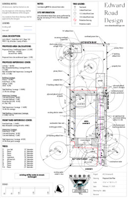
GENERAL NOTES: All dimensions shall be checked on site. NOTES: See drawing 011 for site and tree notes TREE LEGEND: Any discrepancies in the drawings shall be brought to the attention of the designer. Any variations from these drawings shall be approved by the designer. SITE INFORMATION: Site information taken from survey performed by Big Sky Surveying 07/19/23, Felix M Gonzalez 5418 Tree trunk Critical Root Zone 1/2 Critical Root Zone 1/4 Critical Root Zone Protective fencing Protective mulch LEGEND: Existing wall: New wall: LEGAL DESCRIPTION: Lot 4, Block 7, Hyde Park, Vol 2, Page 130 PRTCT, City of Austin, County of Travis PROPOSED AREA CALCULATIONS: Proposed Gross Conditioned Space: 2,323ft2 First Floor: 1,493ft2 Second Floor: 884ft2 Proposed Gross Unconditioned Space: 231ft2 PROPOSED IMPERVIOUS COVER: Lot Area: 7,801ft2 Max Allowable Building Coverage @ 40%: 3,120ft2 Max Allowable Total Impervious Coverage @ 45%: 3,510ft2 Building Coverage: House: 1,439ft2 Front Porch: 157ft2 Garage: 231ft2 Shed: 162ft2 Total Building Coverage: 1,989ft2 25.5% lot coverage Impervious Coverage: Concrete Driveway: 864ft2 Concrete Walkway: 126ft2 Wood Deck @ 50%: 141ft2 A/C Pad: 9ft2 Total Impervious Coverage: 1,140ft2 14.6% lot coverage Total Building + Impervious Coverage: 3,129ft2 / 40.1% FRONT YARD IMPERVIOUS COVER: Front Yard Area: 1,246ft2 Max Allowable Coverage @ 40%: 498ft2 Impervious Coverage: Front Porch: 125ft2 Concrete Driveway: 241ft2 Concrete Walkway: 126ft2 Total Impervious Coverage: 492ft2 39.5% front yard coverage TREES: T1 Live Oak T2 Pecan T3 Pecan T4 Pecan T5 Ligustrum T6 Arizona Ash T7 Pecan T8 Pecan T9 Pecan T10 Pecan 19" diameter 31" diameter 23" diameter 25" diameter 18" diameter 18" diameter 20" diameter 16" diameter 30" diameter 25" diameter 10' setback line incoming overhead power line shed in place since at least 1958 20 01 3 62 7. 1 2 N G shed R5' 0"1/4CRZ R4' 0"1/4CRZ R10' 0" 1/2CRZ R8' 0" 1/2CRZ 2 R 0' 0 " R Z C R 1 6' 0 " R Z C T7 T8 20 2 62 7. 2 9 F N B1 N G 20 1 62 7. 4 8 F N B1 N G privacy fence property line 5' building setback line tent 2 low point 628.38' plywood placed over 8" of mulch 6 62 8. 2 5 C P T N S 6 0D R15' 0" 1/2CRZ R7' 6"1/4CRZ " 0 - ' 0 4 12 19 62 8. 4 1 F N B1 N G 0' 0 " R Z C 3 R 2 6 5 8 . T9 4. wood deck existing electric meter tent 1 low point/tent 2 high point 628.86' wastewater clean out existing gas meter 25' building setback line 11 19 62 8. 5 9 N G 12 17 62 9. 0 6 H O U S E K 3. 11 17 62 8. 8 4 S FC 1 20 01 6 62 8. 6 9 N G 20 01 5 62 8. 7 8 20 01 4 11 16 62 8. 7 9 62 8. 9 9 S FC 1 11 15 62 8. 8 0 S FC 1 S R E CT 12 18 62 8. 8 6 N G 6 2 9.0 0' ' 8 2 . 6 5 1 E " 3 3 0 3 ° 2 6 S ' 11 10 62 9. 3 8 F N B1 N G " 0 - ' 0 4 3. 629.5 tent 1 high point 629.52' R6' 3"1/4CRZ R12' 6" 1/2CRZ T4 5' 0 " R Z C 2 R www.edwardroaddesign.com overhead power line S27°23'45"W 50.03' 20 01 2 62 7. 3 5 N G 62 7. 3 3 N G 20 01 1 20 01 0 62 7. 2 4 N G privacy fence 5' building setback line property line 12 11 62 7. 1 4 F N B2 N G tent 1 low point 627.57' plywood placed over 8" of mulch 2x4s fixed around trunk as protection 12 13 5 62 7. 3 6 62 7. 3 6 C H K 5 C P T N S 6 0D 6 2 7 . 5 20 00 7 62 7. 5 3 N G 20 00 6 62 7. 4 4 N G 20 00 4 62 7. 7 4 N G R4' 6"1/4CRZ R9' 0" 1/2CRZ T6 20 00 5 62 7. 8 1 N G 20 00 3 62 7. 9 9 N G 8' 0 " R Z C 1 R 6 2 8.0 0' 3. 20 00 2 62 7. 9 9 N G 12 15 62 8. 1 2 N G 12 16 62 9. 5 3 H O U S E K 12 07 12 08 62 7. 5 5 N G 62 7. 5 5 S H ED K 12 10 12 09 62 7. 2 8 N G 62 7. 2 6 S H ED K garage 12 05 12 06 62 7. 6 5 S H ED K 62 7. 6 1 N G 11 77 11 78 62 7. 6 5 N G 62 7. 7 7 D R C 1 P T / E T F 11 98 62 7. 5 7 11 97 N G 62 7. 8 0 D R C 3 E / E TF 12 20 62 7. 5 5 S H ED K12 21 62 7. 6 1 N G 11 95 11 96 62 7. 8 0 62 7. 7 0 D R C 3 P T N G 3. 11 75 11 76 62 7. 8 2 N G 62 7. 9 7 D R C 1 P O C 628.00' R6' 3"1/4CRZ 11 94 62 8. 0 3 62 7. 9 0 D R C 3 P O C N G 11 93 4. R12' 6" 1/2CRZ 11 80 62 8. 0 7 11 79 N G 62 8. 0 4 D R C 1 P T / E T F 11 73 11 74 62 8. 2 6 D R C 1 P T P O C 62 8. 1 5 N G 5' 0 " R Z C 2 R material staging 11 72 11 71 62 8. 2 7 N G 62 8. 4 0 D R C 1 P O C 11 70 11 69 62 8. 2 8 N G 62 8. 4 6 D R C 1 P C 628.50' ' 1 1 . 6 5 1 W " 0 3 6 2 ° 2 6 N ' 11 92 11 91 62 8. 0 7 62 8. 1 3 N G D R C 3 P T P O C T10 11 89 11 90 62 8. 2 8 62 8. 11 N G D R C 3 P O C 11 87 11 88 62 8. 3 9 62 8. 2 7 D R C 3 P C N G 3. 4523 avenue b 12 00 62 8. 6 1 N G 3. concrete driveway 11 85 11 86 62 8. 8 3 62 8. 6 9 D R C 3 P T N G 11 68 11 67 62 8. 9 0 D R C 1 P T 62 8. 6 1 N G 11 84 11 83 62 8. 7 0 62 8. 9 2 D R C 3 P O C N G 11 81 11 82 62 9. 0 2 62 8. 7 7 D R C 3 P C N G 10 37 10 38 62 9. 0 1 62 8. 8 0 D R C 2 S D R C 3 S N G 629.0 11 66 11 65 62 8. 8 5 N G 62 9. 0 2 D R C 1 P O C 11 64 11 63 62 8. 8 8 N G 62 9. 1 2 D R C 1 P C concrete washout tent 2 high point 629.40' air spading to be used when drilling within 1/2 CRZ 2x4s fixed around trunk as protection 11 13 62 9. 0 5 G S M T 11 12 11 11 62 9. 2 4 H O U S E K 62 9. 2 8 N G 11 22 62 9. 5 2 N G 11 20 63 0. 2 8 B G P H1 S / ET F R15' 6" 1/2CRZ R7' 9"1/4CRZ 4. T2 11 56 11 55 62 9. 4 9 H O U S E K 62 9. 5 7 N G 11 61 11 62 62 9. 1 6 N G 62 9. 3 1 D R C 1 P T 11 59 11 58 62 9. 3 6 N G 62 9. 4 1 D R C 1 P O C 11 60 11 57 62 9. 4 2 N G 62 9. 4 5 D R C 1 P C 11 54 11 53 62 9. 4 3 N G 62 9. 4 8 D R C 1 P T 11 52 11 51 62 9. 4 3 N G 62 9. 5 2 D R C 1 P O C 11 49 11 50 62 9. 5 7 D R C 1 P C 62 9. 3 6 N G 11 47 62 9. 3 8 C P T R E SE C T IO N covered porch 1' 0 " R Z C 3 R 11 24 63 0. 1 7 B G P H2 S / ET F 11 31 11 30 62 9. 7 5 N G 62 9. 8 5 S W4 S / E T F 11 42 62 9. 7 6 N G 11 25 63 0. 2 2 B G P H2 E / ET F 11 29 62 9. 6 0 N G 11 21 63 0. 2 2 B G P H1 E / ET F 11 23 62 9. 6 3 N G 11 26 11 28 63 0. 2 9 62 9. 5 2 B G P H3 S / ET F N G 11 27 63 0. 2 2 B G P H3 E / ET F 10 39 10 40 62 9. 0 8 62 8. 7 7 D R C 2 P C N G 10 41 10 42 62 9. 1 4 62 8. 8 9 D R C 2 P O C N G 10 43 10 44 62 9. 2 2 62 9. 1 0 D R C 2 P T N G " R Z R 4 ' 6 1 / 4 C T5 10 46 10 45 62 9. 11 62 9. 2 8 N G D R C 2 11 45 62 8. 7 7 N G / F N B2 S R9' 0" 1/2CRZ R18' 0"CRZ tent 1 high point 629.07' 10 48 10 47 62 9. 4 0 62 9. 2 7 D R C 2 N G 11 44 62 9. 1 2 N G 11 33 11 32 62 9. 7 5 N G 62 9. 8 3 S W4 P C 11 40 11 41 62 9. 8 4 62 9. 8 1 S W4 P T N G 10 59 10 58 62 9. 7 9 N G 62 9. 9 0 S W1 P T 10 57 10 56 62 9. 8 2 N G 62 9. 8 9 S W1 P O C 10 53 10 54 62 9. 8 6 62 9. 8 2 S W2 P T N G 3. walkway 6 dumpster 2 9 . 5 R11' 6" 1/2CRZ R5' 9"1/4CRZ T3 5. 3' 0 " R Z C 2 R " R Z R 4 ' 9 1 / 4 C 10 36 10 35 62 9. 5 9 62 9. 7 1 D R C 1 N G R9' 6" 1/2CRZ R19' 0"CRZ porta potty 9'-0" N27°12'00"E 49.85' T1 49'-10 1/4" 4. construction route avenue b existing utility routes to remain unchanged existing water meter + line SCALE: t f 0 t f 5 t f 0 1 t f 0 2 t f 0 3 N Project 4523 Avenue B Drawing Proposed Site Plan Scale Date 1/16" = 1' @ 11 x 17 February 11, 2025 Drawing No. 010 Revision GENERAL NOTES: All dimensions shall be checked on site. Any discrepancies in the drawings shall be brought to the attention of the designer. Any variations from these drawings shall be approved by the designer. LEGEND: Existing wall: Wall above: New wall: Window at existing wall: Window at new wall: Smoke Detector: Smoke/Carbon Monoxide Detector: Exhaust Fan: s/cm s E www.edwardroaddesign.com SCALE: t f 0 t f 5 t f 0 1 t f 0 2 GENERAL CONDITIONS 1. These documents comprise a portion of a contract between the Owner and the General Contractor. No contract is implied or stated between the Owner and any other party, nor between the Home Designer and any party. 2. No set of contract documents is able to contain all the information required to construct a project. Interpretation by the General Contractor is required. By use of these documents, both the Owner and the General Contractor assent to this understanding of the nature of contract documents. 3. The General Contractor is responsible for the provision of minor details and appurtenances not shown in the contract documents. 4. The General Contractor and his/her subcontractors are responsible for the final design of the HVAC, plumbing, and electrical systems. 5. The General Contractor may not revise or modify the contract documents, in whole or in part, without the prior approval of the Owner. Consultation with the Home Designer beforehand is strongly recommended. 6. The General Contractor may not modify the plans, elevations, or site plan shown in the contract documents without obtaining Home Designer consultation and Owner approval beforehand. 7. Should the Owner request changes to the contract documents, the General Contractor is responsible for ensuring that the changes do not result in a built condition that does not comply with codes and/or regulations. Consultation with the Home Designer and/or an Inspector is highly recommended. 8. The Home Designer is not an inspector and is not liable for the General Contractor's failure to execute the Work in accordance with the contract documents and/or in conformance with any and/or all applicable codes, laws, statutes and regulations. NOTES REGARDING CODES, REGULATIONS, STANDARDS, PERMITS and INSPECTIONS 1. The General Contractor is responsible for ensuring built compliance with all codes, regulations, and standards such as may be in force. These codes include but may not be limited to: 2021 International Energy Conservation Code 2023 Amended National Electrical Code 2021 International Fire Code 2021 Uniform Mechanical Code 2021 Uniform Plumbing Code 2021 International Residential Code (as locally amended) 2015 International Wildland-Urban Interface Code 2. Should the General Contractor become aware of a condition shown or depicted in the contract documents that would result in a violation of any code or regulation listed above, the General Contractor shall contact the Home Designer immediately for resolution. 3. The General Contractor shall be responsible for obtaining any permit not provided beforehand by the Owner. 4. The General Contractor and/or his/her subcontractors shall be responsible for coordinating all required inspections. 5. The Owner and/or the General Contractor shall commission a third-party inspector. Failure on the part of the Owner and/or the General Contractor to retain a third-party inspector shall release the Home Designer from any and all liability for the project. 6. Neither the Owner nor the Home Designer shall be considered to act in the role of an Inspector. While the Owner and the Home Designer shall endeavor to alert the General Contractor to any perceived or observed defect in the construction, failure to do so shall not in any way relieve the General Contractor from his/her obligation to ensure that the built work is safe, of good quality, and compliant with all relevant codes and regulations. 7. The General Contractor is responsible for ensuring that all work, whether performed by subcontractors or by the General Contractor him/herself, is of good workmanship and quality. NOTES REGARDING CERTAIN AREA, CLEAR SPACE, AND CEILING HEIGHT REQUIREMENTS. (Ref: 2021 International Residential Code as locally amended) 1. Habitable / occupiable rooms and hallways with flat ceilings shall have a ceiling height of not less than 7'. (R305.1) 2. Habitable / occupiable rooms with sloping ceilings in which a minimum floor area of 70ft2 is required by code shall have a minimum of 35ft2 in which the ceiling height is not less than 7'. (R305.1, exception 1) 3. Bathrooms, toilet rooms, and laundry rooms with flat ceilings shall have a ceiling height of not less than 6' 8". (R305.1) 4. Sinks in bathrooms with sloped ceilings shall have a clear space directly in front of the sink with a ceiling height of not less than 6' 8". The clear space in front of a sink shall be as wide as the sink and a minimum of 21" deep as measured perpendicularly from the furthest edge of the sink or counter from the wall. (R305.1; R307.1) 5. Toilets in bathrooms and toilet rooms with sloped ceilings shall have a clear space directly in front of the toilet with a ceiling height of not less than 6' 8". The clear space in front of a toilet shall be 32" wide (16" to either side of the centerline of the toilet) and shall be a minimum of 21" deep as measured perpendicularly from the furthest edge of the toilet seat from the wall. (R305.1; R307.1) 6. Tubs and/or showers equipped with showerheads in bathrooms with sloped ceilings shall have a ceiling height of not less than 6' 8" above an area not less than 30" by 30" at the showerhead. (R305.1, exception 2) 7. When measured vertically above the permitted handrail height and at 6' 8" above the sloped line between tread nosings, the clear width of stairs (except spiral stairs) and ramps shall be not less than 36". When measured at and below the permitted handrail height, the clear width of stairs (except spiral stairs) and ramps shall be not less than 31-1/2" for stairs or ramps with handrails on one side and shall be not less than 27" for stairs or ramps with handrails on two sides. (R311.7) 8. The headroom above stairs and ramps shall be not less than 6' 8" as measured vertically from the sloped line between tread nosings. (R311.7.2) The required headroom may be reduced to 6' 6" for spiral stairs. (R311.7.10.1) Project 4523 Avenue B Drawing General Notes Scale Date 1/8" = 1' @ 11 x 17 February 11, 2025 Drawing No. 000 Revision GENERAL NOTES: All dimensions shall be checked on site. NOTES: See drawing 011 for site and tree notes Any discrepancies in the drawings shall be brought to the attention of the designer. Any variations from these drawings shall be approved by the designer. SITE INFORMATION: Site information taken from survey performed by Big Sky Surveying 07/19/23, Felix M Gonzalez 5418 LEGEND: Existing wall: New wall: LEGAL DESCRIPTION: Lot 4, Block 7, Hyde Park, Vol 2, Page 130 PRTCT, City of Austin, County of Travis EXISTING AREA CALCULATIONS: Existing Gross Conditioned Space: 1,439ft2 Existing Gross Unconditioned Space: 231ft2 EXISTING IMPERVIOUS COVER: Lot Area: 7,801ft2 Max Allowable Building Coverage @ 40%: 3,120ft2 Max Allowable Total Impervious Coverage @ 45%: 3,510ft2 Building Coverage: House: 1,439ft2 Front Porch: 157ft2 Garage: 231ft2 Shed: 162ft2 Total Building Coverage: 1,989ft2 25.5% lot coverage Impervious Coverage: Concrete Driveway: 864ft2 Concrete Walkway: 126ft2 Wood Deck @ 50%: 141ft2 A/C Pad: 9ft2 Total Impervious Coverage: 1,140ft2 14.6% lot coverage Total Building + Impervious Coverage: 3,129ft2 / 40.1% FRONT YARD IMPERVIOUS COVER: Front Yard Area: 1,246ft2 Max Allowable Coverage @ 40%: 498ft2 Impervious Coverage: Front Porch: 125ft2 Concrete Driveway: 241ft2 Concrete Walkway: 126ft2 Total Impervious Coverage: 492ft2 39.5% front yard coverage TREES: T1 Live Oak T2 Pecan T3 Pecan T4 Pecan T5 Ligustrum T6 Arizona Ash T7 Pecan T8 Pecan T9 Pecan T10 Pecan 19" diameter 31" diameter 23" diameter 25" diameter 18" diameter 18" diameter 20" diameter 16" diameter 30" diameter 25" diameter www.edwardroaddesign.com privacy fence 5' building setback line property line 12 11 62 7. 1 4 F N B2 N G 10' setback line incoming overhead power line shed in place since at least 1958 20 01 3 62 7. 1 2 N G shed R5' 0"1/4CRZ R4' 0"1/4CRZ R10' 0" 1/2CRZ R8' 0" 1/2CRZ 2 R 0' 0 " R Z C R 1 6' 0 " R Z C T7 T8 20 2 62 7. 2 9 F N B1 N G 20 1 62 7. 4 8 F N B1 N G privacy fence property line 5' building setback line overhead power line S27°23'45"W 50.03' 20 01 2 62 7. 3 5 N G 62 7. 3 3 N G 20 01 1 20 01 0 62 7. 2 4 N G 12 13 5 62 7. 3 6 62 7. 3 6 C H K 5 C P T N S 6 0D 6 2 7 . 5 20 00 7 62 7. 5 3 N G 20 00 6 62 7. 4 4 N G 20 00 4 62 7. 7 4 N G R4' 6"1/4CRZ R9' 0" 1/2CRZ T6 20 00 5 62 7. 8 1 N G 20 00 3 62 7. 9 9 N G 8' 0 " R Z C 1 R 6 2 8.0 0' 20 00 2 62 7. 9 9 N G 12 15 62 8. 1 2 N G 12 16 62 9. 5 3 H O U S E K 12 07 12 08 62 7. 5 5 N G 62 7. 5 5 S H ED K 12 10 12 09 62 7. 2 8 N G 62 7. 2 6 S H ED K garage 12 05 12 06 62 7. 6 5 S H ED K 62 7. 6 1 N G 11 77 11 78 62 7. 6 5 N G 62 7. 7 7 D R C 1 P T / E T F 11 98 62 7. 5 7 11 97 N G 62 7. 8 0 D R C 3 E / E TF 12 20 62 7. 5 5 S H ED K12 21 62 7. 6 1 N G 11 95 11 96 62 7. 8 0 62 7. 7 0 D R C 3 P T N G R6' 3"1/4CRZ 11 94 62 8. 0 3 62 7. 9 0 D R C 3 P O C N G 11 93 11 75 11 76 62 7. 8 2 N G 62 7. 9 7 D R C 1 P O C 628.00' R12' 6" 1/2CRZ 11 80 62 8. 0 7 11 79 N G 62 8. 0 4 D R C 1 P T / E T F 11 73 11 74 62 8. 2 6 D R C 1 P T P O C 62 8. 1 5 N G 5' 0 " R Z C 2 R 11 72 11 71 62 8. 2 7 N G 62 8. 4 0 D R C 1 P O C 11 70 11 69 62 8. 2 8 N G 62 8. 4 6 D R C 1 P C 628.50' 11 92 11 91 62 8. 0 7 62 8. 1 3 N G D R C 3 P T P O C T10 11 89 11 90 62 8. 2 8 62 8. 11 N G D R C 3 P O C 11 87 11 88 62 8. 3 9 62 8. 2 7 D R C 3 P C N G ' 1 1 . 6 5 1 W " 0 3 6 2 ° 2 6 N ' 4523 avenue b 12 00 62 8. 6 1 N G 11 99 62 8. 4 3 F N B2 N G concrete driveway 11 68 11 67 62 8. 9 0 D R C 1 P T 62 8. 6 1 N G 11 85 11 86 62 8. 8 3 62 8. 6 9 D R C 3 P T N G 11 84 11 83 62 8. 7 0 62 8. 9 2 D R C 3 P O C N G 11 81 11 82 62 9. 0 2 62 8. 7 7 D R C 3 P C N G 10 37 10 38 62 9. 0 1 62 8. 8 0 D R C 2 S D R C 3 S N G 629.0 11 66 11 65 62 8. 8 5 N G 62 9. 0 2 D R C 1 P O C 11 64 11 63 62 8. 8 8 N G 62 9. 1 2 D R C 1 P C ' 8 2 . 6 5 1 E " 3 3 0 3 ° 2 6 S ' 11 19 62 8. 5 9 N G 12 17 62 9. 0 6 H O U S E K 11 17 62 8. 8 4 S FC 1 20 01 6 62 8. 6 9 N G 20 01 5 62 8. 7 8 20 01 4 11 16 62 8. 7 9 62 8. 9 9 S FC 1 11 15 62 8. 8 0 S FC 1 S R E CT 12 18 62 8. 8 6 N G 6 2 9.0 0' existing electric meter 6 62 8. 2 5 C P T N S 6 0D R15' 0" 1/2CRZ R7' 6"1/4CRZ 12 19 62 8. 4 1 F N B1 N G 0' 0 " R Z C 3 R 2 6 5 8 . T9 wood deck wastewater clean out existing gas meter 25' building setback line R6' 3"1/4CRZ R12' 6" 1/2CRZ T4 5' 0 " R Z C 2 R existing water meter + line 11 13 62 9. 0 5 G S M T 11 10 62 9. 3 8 F N B1 N G 11 12 11 11 62 9. 2 4 H O U S E K 62 9. 2 8 N G 11 22 62 9. 5 2 N G 11 20 63 0. 2 8 B G P H1 S / ET F R15' 6" 1/2CRZ R7' 9"1/4CRZ T2 11 56 11 55 62 9. 4 9 H O U S E K 62 9. 5 7 N G 11 61 11 62 62 9. 1 6 N G 62 9. 3 1 D R C 1 P T 11 59 11 58 62 9. 3 6 N G 62 9. 4 1 D R C 1 P O C 11 60 11 57 62 9. 4 2 N G 62 9. 4 5 D R C 1 P C 11 54 11 53 62 9. 4 3 N G 62 9. 4 8 D R C 1 P T 11 52 11 51 62 9. 4 3 N G 62 9. 5 2 D R C 1 P O C 11 49 11 50 62 9. 5 7 D R C 1 P C 62 9. 3 6 N G 11 47 62 9. 3 8 C P T R E SE C T IO N covered porch 1' 0 " R Z C 3 R 11 24 63 0. 1 7 B G P H2 S / ET F 11 31 11 30 62 9. 7 5 N G 62 9. 8 5 S W4 S / E T F 11 42 11 43 62 9. 8 6 62 9. 7 6 S W4 E / ET F N G 11 25 63 0. 2 2 B G P H2 E / ET F 11 29 62 9. 6 0 N G 11 21 63 0. 2 2 B G P H1 E / ET F 11 23 62 9. 6 3 N G 11 26 11 28 63 0. 2 9 62 9. 5 2 B G P H3 S / ET F N G 11 27 63 0. 2 2 B G P H3 E / ET F 10 39 10 40 62 9. 0 8 62 8. 7 7 D R C 2 P C N G 10 41 10 42 62 9. 1 4 62 8. 8 9 D R C 2 P O C N G 10 43 10 44 62 9. 2 2 62 9. 1 0 D R C 2 P T N G " R Z R 4 ' 6 1 / 4 C T5 10 46 10 45 62 9. 11 62 9. 2 8 N G D R C 2 11 45 62 8. 7 7 N G / F N B2 S R9' 0" 1/2CRZ R18' 0"CRZ 629.5 11 33 11 32 62 9. 7 5 N G 62 9. 8 3 S W4 P C 11 40 11 41 62 9. 8 4 62 9. 8 1 S W4 P T N G 10 59 10 58 62 9. 7 9 N G 62 9. 9 0 S W1 P T 10 57 10 56 62 9. 8 2 N G 62 9. 8 9 S W1 P O C 10 53 10 54 62 9. 8 6 62 9. 8 2 S W2 P T N G N27°12'00"E 49.85' T1 stone walkway 10 48 10 47 62 9. 4 0 62 9. 2 7 D R C 2 N G 11 44 62 9. 1 2 N G 6 2 9 . 5 R11' 6" 1/2CRZ R5' 9"1/4CRZ T3 " R Z R 4 ' 9 1 / 4 C 10 36 10 35 62 9. 5 9 62 9. 7 1 D R C 1 N G R9' 6" 1/2CRZ 3' 0 " R Z C 2 R R19' 0"CRZ avenue b Project 4523 Avenue B Drawing Existing Site Plan Scale Date 1/16" = 1' @ 11 x 17 February 11, 2025 Drawing No. 001 Revision SCALE: t f 0 t f 5 t f 0 1 t f 0 2 t f 0 3 N GENERAL NOTES: All dimensions shall be checked on site. Any discrepancies in the drawings shall be brought to the attention of the designer. Any variations from these drawings shall be approved by the designer. LEGEND: Existing wall: New wall: www.edwardroaddesign.com existing shed present since at least 1958 Project 4523 Avenue B Drawing Existing Photos Scale Date 1/16" = 1' @ 11 x 17 February 11, 2025 Drawing No. 002 Revision SCALE: t f 0 t f 5 t f 0 1 t f 0 2 t f 0 3 GENERAL NOTES: All dimensions shall be checked on site. Any discrepancies in the drawings shall be brought to the attention of the designer. Any variations from these drawings shall be approved by the designer. LEGEND: Existing wall: Wall above: New wall: Window at existing wall: Window at new wall: Smoke Detector: Smoke/Carbon Monoxide Detector: Exhaust Fan: s/cm s E EXISTING AREA CALCULATION: Existing Gross Conditioned Area: 1,439ft2 Existing Gross Unconditioned Area: 0ft2 SCALE: t f 0 t f 5 t f 0 1 t f 0 2 N deck bedroom 3 13' 5" x 15' 7" 191 ft sq 9' 4" clng hght closet laundry 5' 0" x 6' 4" 32 ft sq 9' 5" clng hght pantry 7' 9" x 6' 4" 49 ft sq 9' 4" clng hght hall 9' 5" clng hght bath 2 7' 8" x 6' 1" 44 ft sq 9' 5" clng hght f/f dw kitchen 13' 0" x 9' 5" 122 ft sq 9' 4" clng hght dining room 13' 0" x 12' 1" 156 ft sq 9' 4" clng hght bedroom 2 13' 0" x 15' 11" 204 ft sq 9' 3" clng hght closet closet bath 1 9' 8" x 6' 2" 59 ft sq 9' 4" clng hght living room 13' 0" x 11' 11" 149 ft sq 9' 4" clng hght bedroom 1 13' 0" x 11' 11" 154 ft sq 9' 4" clng hght covered porch 9' 8" clng hght www.edwardroaddesign.com Project 4523 Avenue B Drawing Existing Floor Plan Scale Date 1/8" = 1' @ 11 x 17 February 11, 2025 Drawing No. 100 Revision GENERAL NOTES: All dimensions shall be checked on site. Any discrepancies in the drawings shall be brought to the attention of the designer. Any variations from these drawings shall be approved by the designer. LEGEND: Existing wall: Wall above: New wall: Window at existing wall: Window at new wall: Smoke Detector: Smoke/Carbon Monoxide Detector: Exhaust Fan: s/cm s E EXISTING AREA CALCULATION: Existing Gross Conditioned Area: 1,439ft2 Existing Gross Unconditioned Area: 0ft2 SCALE: t f 0 t f 5 t f 0 1 t f 0 2 N www.edwardroaddesign.com Project 4523 Avenue B Drawing Existing Roof Plan Scale Date 1/8" = 1' @ 11 x 17 February 11, 2025 Drawing No. 101 Revision GENERAL NOTES: All dimensions shall be checked on site. Any discrepancies in the drawings shall be brought to the attention of the designer. Any variations from these drawings shall be approved by the designer. LEGEND: Existing wall: Wall above: New wall: Window at existing wall: Window at new wall: Smoke Detector: Smoke/Carbon Monoxide Detector: Exhaust Fan: s/cm s E Left Side Elevation " 4 - ' 9 " 4 - ' 9 SCALE: t f 0 t f 5 t f 0 1 t f 0 2 Right Side Elevation " 4 - ' 9 " 4 - ' 9 www.edwardroaddesign.com Front Elevation Rear Elevation Project 4523 Avenue B Drawing Existing Elevations Scale Date 1/8" = 1' @ 11 x 17 February 11, 2025 Drawing No. 110 Revision GENERAL NOTES: All dimensions shall be checked on site. Any discrepancies in the drawings shall be brought to the attention of the designer. Any variations from these drawings shall be approved by the designer. LEGEND: Existing wall: Wall above: New wall: Window at existing wall: Window at new wall: Smoke Detector: Smoke/Carbon Monoxide Detector: Exhaust Fan: s/cm s E SCALE: t f 0 t f 5 t f 0 1 t f 0 2 N section of eaves removed doors + wall removed www.edwardroaddesign.com section of eaves removed section of eaves removed door + section of wall removed Project 4523 Avenue B Drawing Demo Plan Scale Date 1/8" = 1' @ 11 x 17 February 11, 2025 Drawing No. 150 Revision GENERAL NOTES: All dimensions shall be checked on site. Any discrepancies in the drawings shall be brought to the attention of the designer. Any variations from these drawings shall be approved by the designer. LEGEND: Existing wall: New wall: www.edwardroaddesign.com SITE NOTES: All work to conform to the City of Austin standards for tree preservation. 1. No cut & fill greater than 4" within the 1/2 CRZ of any protected tree. 2. A minimum of 50% of the CRZ of a protected tree will be preserved at natural grade, with natural ground cover. 3. All protected trees within the construction area to be protected by minimum 5' high chain link fencing around the CRZ. Any area of the CRZ that is not fenced to allow for reasonable working space will be covered with 8" layer of mulch to City of Austin standards. 4. There will be minimal impact to the existing tree canopies by the construction. No more than 25% pruning of any protected canopy. 5. Excavation construction route to avoid 1/2 CRZ of each protected tree on the lot. 6. Erosion control barriers to be installed prior to commencement of construction 7. Builder to resculpture topo/finished grade to provide proper drainage of surface water away from building as required 8. All construction materials and waste to be stored on site during construction 9. Contractor shall clean up areas affected by daily work and remove debris and materials from the site upon completion of the work 10. Utility line locations are approximates, General Contractor to field verify for exact locations 11. Verify meter and utility service locations prior to installation 12. All existing utility lines (water, wastewater, gas and electric) to be repurposed. There will be no trenching or digging within the CRZs of protected trees. SCALE: t f 0 t f 5 t f 0 1 t f 0 2 t f 0 3 Project 4523 Avenue B Drawing Site Plan Notes Scale Date 1/16" = 1' @ 11 x 17 February 11, 2025 Drawing No. 011 Revision GENERAL NOTES: All dimensions shall be checked on site. NOTES: See drawings 000 + 300 for notes Any discrepancies in the drawings shall be brought to the attention of the designer. Any variations from these drawings shall be approved by the designer. LEGEND: Existing wall: Wall above: New wall: Window at existing wall: Window at new wall: Smoke Detector: Smoke/Carbon Monoxide Detector: Exhaust Fan: s/cm s E PROPOSED AREA CALCULATION: Proposed Gross Conditioned Area: 2,323ft2 First Floor: 1,439ft2 Second Floor: 884ft2 Proposed Gross Unconditioned Area: 0ft2 SCALE: t f 0 t f 5 t f 0 1 t f 0 2 N replace with safety glass up to 18 equal risers + 36" high continuous handrail, per code 10. 3'-0" deck 11. " 0 - ' 3 dw kitchen 13' 0" x 9' 5" 122 ft sq 9' 4" clng hght dining room 13' 0" x 12' 1" 156 ft sq 9' 4" clng hght bedroom 3 13' 5" x 15' 7" 191 ft sq 9' 4" clng hght 3. s closet hall 9' 5" clng hght s/cm 3. bath 2 7' 8" x 6' 1" 44 ft sq 9' 5" clng hght f/f s 3. bedroom 2 13' 0" x 15' 11" 204 ft sq 9' 3" clng hght closet closet bath 1 9' 8" x 6' 2" 59 ft sq 9' 4" clng hght living room 13' 0" x 11' 11" 149 ft sq 9' 4" clng hght living room 13' 0" x 11' 11" 154 ft sq 9' 4" clng hght covered porch 9' 8" clng hght www.edwardroaddesign.com Project 4523 Avenue B Drawing Proposed First Floor Plan Scale Date 1/8" = 1' @ 11 x 17 February 11, 2025 Drawing No. 200 Revision GENERAL NOTES: All dimensions shall be checked on site. NOTES: See drawings 000 + 300 for notes Any discrepancies in the drawings shall be brought to the attention of the designer. Any variations from these drawings shall be approved by the designer. LEGEND: Existing wall: Wall above: New wall: Window at existing wall: Window at new wall: Smoke Detector: Smoke/Carbon Monoxide Detector: Exhaust Fan: s/cm s E PROPOSED AREA CALCULATION: Proposed Gross Conditioned Area: 2,323ft2 First Floor: 1,439ft2 Second Floor: 884ft2 Proposed Gross Unconditioned Area: 0ft2 DOOR SCHEDULE: D1-3: 2' 8" w x 6' 8" h door to fit new opening. D4-5: 3' 0" w x 6' 8" h door to fit new opening. D6: 2' 6" w x 6' 8" h door to fit new opening. D7: 2' 8" w x 6' 8" h door to fit new opening. D8: 5' 0" w x 6' 8" h bifold door to fit new opening. SCALE: t f 0 t f 5 t f 0 1 t f 0 2 N up to 18 equal risers + 36" high continuous handrail, per code 5. W13 5. W12 " 0 - ' 3 open to below 11. 3'-6" e g d e l 10. W14 dryer 1. E washer D8 " 2 - ' 4 s/cm D1 3. 3'-8" D3 D7 s 3. W11 W10 W9 office 13' 10" x 10' 2" 132 ft sq 9' 0" clng hght s 3. D2 3'-0" 1. E 2. 3'-0" W15 4. W16 bedroom 5 13' 11" x 15' 10" 218 ft sq 9' 0" clng hght D6 s 3. t e s o l c D4 c l o s e t D5 bedroom 4 13' 11" x 14' 6" 154 ft sq 9' 0" clng hght " 1 - ' 2 1 11'-2" W1 W2 W3 W4 bath 3 9' 10" x 5' 6" 57 ft sq 9' 0" clng hght W8 5. W7 W6 4. W5 www.edwardroaddesign.com WINDOW SCHEDULE: W1: 2' 6" w x 4' 6" h sash window to fit new opening. W2-3: 2' 6" w x 2' 8" h casement window, to fit new opening. W4: 2' 6" w x 4' 6" h sash window to fit new opening. W5-6: 2' 6" w x 5' 6" h sash window to fit new opening. 6.1ft2 egress opening. W7: 2' 6" w x 3' 6" h sash window to fit new opening. W8: 2' 6" w x 5' 6" h sash window to fit new opening. W9: 2' 6" w x 4' 6" h sash window to fit new opening. W10: 2' 6" w x 3' 6" h sash window, to fit new opening. W11: 2' 6" w x 4' 6" h sash window to fit new opening. W12-16: 2' 6" w x 5' 6" h sash window to fit new opening. 6.1ft2 egress opening. Project 4523 Avenue B Drawing Proposed Second Floor Plan Scale Date 1/8" = 1' @ 11 x 17 February 11, 2025 Drawing No. 201 Revision GENERAL NOTES: All dimensions shall be checked on site. NOTES: See drawings 000 + 300 for notes Any discrepancies in the drawings shall be brought to the attention of the designer. Any variations from these drawings shall be approved by the designer. LEGEND: Existing wall: Wall above: New wall: Window at existing wall: Window at new wall: Smoke Detector: Smoke/Carbon Monoxide Detector: Exhaust Fan: s/cm s E PROPOSED AREA CALCULATION: Proposed Gross Conditioned Area: 2,323ft2 First Floor: 1,439ft2 Second Floor: 884ft2 Proposed Gross Unconditioned Area: 0ft2 SCALE: t f 0 t f 5 t f 0 1 t f 0 2 N www.edwardroaddesign.com Project 4523 Avenue B Drawing Proposed Roof Plan Scale Date 1/8" = 1' @ 11 x 17 February 11, 2025 Drawing No. 202 Revision GENERAL NOTES: All dimensions shall be checked on site. NOTES: See drawings 000 + 300 for notes Any discrepancies in the drawings shall be brought to the attention of the designer. Any variations from these drawings shall be approved by the designer. LEGEND: Existing wall: Wall above: New wall: Window at existing wall: Window at new wall: Smoke Detector: Smoke/Carbon Monoxide Detector: Exhaust Fan: s/cm s E PROPOSED AREA CALCULATION: Proposed Gross Conditioned Area: 2,323ft2 First Floor: 1,439ft2 Second Floor: 884ft2 Proposed Gross Unconditioned Area: 0ft2 DOOR SCHEDULE: D1-3: 2' 8" w x 6' 8" h door to fit new opening. D4-5: 3' 0" w x 6' 8" h door to fit new opening. D6: 2' 6" w x 6' 8" h door to fit new opening. D7: 2' 8" w x 6' 8" h door to fit new opening. D8: 5' 0" w x 6' 8" h bifold door to fit new opening. www.edwardroaddesign.com slope to match existing eaves protrude less than 2' side setback 9 3/8" " 0 - ' 5 1 W2 W1 6. W3 W4 " 0 - ' 7 1 " 0 - ' 5 1 " 0 - ' 9 " 4 - ' 9 " 0 - ' 9 " 4 - ' 9 W10 W9 W11 5. W12 5. W13 6. 5. tent 1 629.52' 5'-0" Front Elevation property line 5'-0" tent 1 629.07' replace with safety glass Rear Elevation WINDOW SCHEDULE: W1: 2' 6" w x 4' 6" h sash window to fit new opening. W8: 2' 6" w x 5' 6" h sash window to fit new opening. W2-3: 2' 6" w x 2' 8" h casement window, to fit new opening. W9: 2' 6" w x 4' 6" h sash window to fit new opening. W4: 2' 6" w x 4' 6" h sash window to fit new opening. W10: 2' 6" w x 3' 6" h sash window, to fit new opening. SCALE: W5-6: 2' 6" w x 5' 6" h sash window to fit new opening. 6.1ft2 egress opening. W11: 2' 6" w x 4' 6" h sash window to fit new opening. t f 0 t f 5 t f 0 1 t f 0 2 W7: 2' 6" w x 3' 6" h sash window to fit new opening. W12-16: 2' 6" w x 5' 6" h sash window to fit new opening. 6.1ft2 egress opening. Project 4523 Avenue B Drawing Proposed Front + Rear Elevations Scale Date 1/8" = 1' @ 11 x 17 February 11, 2025 Drawing No. 210 Revision GENERAL NOTES: All dimensions shall be checked on site. Any discrepancies in the drawings shall be brought to the attention of the designer. Any variations from these drawings shall be approved by the designer. LEGEND: Existing wall: Wall above: New wall: Window at existing wall: Window at new wall: Smoke Detector: Smoke/Carbon Monoxide Detector: Exhaust Fan: s/cm s E PROPOSED AREA CALCULATION: Proposed Gross Conditioned Area: 2,323ft2 First Floor: 1,439ft2 Second Floor: 884ft2 Proposed Gross Unconditioned Area: 0ft2 NOTES: See drawings 000 + 300 for notes and drawing 210 for door + window schedule " 0 - ' 9 " 4 - ' 9 tent 2 low point 628.38' Left Side Elevation " 0 - ' 7 1 " 0 - ' 5 1 6. W14 4. W15 W16 " 8 / 5 0 - ' 6 2 www.edwardroaddesign.com " 0 - ' 7 1 " 0 - ' 5 1 tent 2 40'-0" tent 1 low point/tent 2 high point 628.86' tent 1 40'-0" A.A.G. 629.03' tent 1 high point 629.52' building line SCALE: t f 0 t f 5 t f 0 1 t f 0 2 tent 1 high point 629.07' Right Side Elevation tent 1 40'-0" tent 2 high point 629.40' tent 2 6. 4. W5 W6 5. W7 W8 " 0 - ' 9 " 4 - ' 9 Project 4523 Avenue B Drawing Proposed Side Elevations Scale Date 1/8" = 1' @ 11 x 17 February 11, 2025 Drawing No. 211 Revision GENERAL NOTES: All dimensions shall be checked on site. Any discrepancies in the drawings shall be brought to the attention of the designer. Any variations from these drawings shall be approved by the designer. LEGEND: Existing wall: Wall above: New wall: Window at existing wall: Window at new wall: Smoke Detector: Smoke/Carbon Monoxide Detector: Exhaust Fan: s/cm s E www.edwardroaddesign.com SCALE: t f 0 t f 5 t f 0 1 t f 0 2 NOTES: All work to conform to the requirements of the applicable building codes per 2021 IRC 1. INTERIOR EXHAUST FANS Provide Clothes Dryer Exhaust System at laundry enclosure, Per 2021 IRC section M1502 Externally ducted kitchen exhaust hood provided to kitchen cooking area. Hood not to exceed 400 CFM ventilation,Per 2021 IRC section M1503 All bathrooms and laundry to have switched exhaust fans with at least 50 CFM ventilation. Fans to duct directly to the outside. Air removedby a mechanical exhaust system shall be discharged to the outside, not into an attic, soffit, ridge vent or crawl space, Per 2021 IRC section M1504.3 All exhaust systems to have a gravity operated louvers to close when the system is not operating. All exhaust system vents to be protected from weather by overhanging eaves. 2. TOILET, BATH & SHOWER SPACES All fixtures shall be spaced as per details in R307 figure 307.1 and 2021 UPC 402.5 3. SMOKE & CARBON MONOXIDE ALARMS All carbon monoxide and smoke alarms shall be hard wired with a battery back up. A carbon monoxide alarm shall be installed in the immediate vicinity of each bedroom/sleeping area in accordance with R315.3. A smoke alarm shall be installed in the immediate vicinity outside of each bedroom/sleeping area and inside each bedroom in accordance with R314.3 and R314.4. “General Contractor is responsible that the dwelling unit to be equipped with an approved Smoke Detectors system at corresponding locations, in accordance with 2021 IRC Section R314.” “General Contractor shall verify for Smoke Detectors to be located at least 36” away from horizontal path of mechanical air flow. Per 2007 NFPA 72 Chapter 11.” “General Contractor is responsible that the dwelling unit to be equipped with an approved Carbon Monoxide Alarm at corresponding locations, in accordance with 2021 IRC Section R315." 4. EGRESS -Every sleeping room shall have at least one operable emergency escape and rescue opening with a window sill height of not more than 44" above finished floor in accordance with R310.1 and R310.2.3. -All emergency escape and rescue openings shall have a minimum net clear opening of 5.7ft2 in accordance with R310.2.1. -The minimum net clear opening height of the escape and rescue opening shall not be less than 24" and the minimum net clear opening width shall be not less than 20" in accordance with R310.2.2. -The required exit door shall be a single hinged door not less than 32" clear in width and 78" clear in height in accordance with R310.3 and R311.2 -There shall be a landing/floor on each side of each exterior door with a minimum width of the door served. The landings at the required egress door will not be more than 1.5" lower than the top of the threshold. Exterior landings may not be more than 7.75" below the top of the threshold provided the door does not swing over the landing in accordance with R311.3 & R311.3.1. 5. SAFETY GLAZING -Tempered safety glass required in the floowing locations/uses: -Panels on doors -Panels adjacent to a door that are less than 60" above the walking surface, provided that the panel is in the same plane of the door in a closed position and within 24" of either side of the door or where the panel is perpendicular and within 24" of the hinge side of an in-swing door. -Panels in windows where the individual panel exceeds 9ft2 and the bottom of the glazing is 18" above the floor and the top edge is over 36" above the floor and the walking surface is within 36" of the glazing measured horizontally and in a straight line. -Guards and railings -Walls, enclosures or fences containing or facing hot tubs, spas, whirlpools, saunas, steam rooms, bathtubs, showers and swiming pools where the bottom edge of the glazing is less than 60" from the walking surface. EXCEPTION: if the glazing is more than 60" from the edge of a bathtub, hot tub, spa, whirlpool or pool, shower, sauna or steam room. All in accordance with R308.4 6. EXTERIOR WALLS Construction, projections, openings and penetrations of exterior walls of dwelling and accessory buildings shall comply with the standards in IRC Table R302.1(1) and R302.1 Local Amendments. 7. ROOF VENTILATION Roof ventilation shall comply with the requirements of IRC R806 including the minimum net free area of vents proposed at each location. Required ventilation shall open directly to the outside and shall provide a minimum NFA of 1/150 of the area to be vented. Unvented attic and unvented rafter assemblies shall comply with R806.5. 8. GARAGE SEPARATION Separation and opening protection between the dwelling and garage shall comply with the requirements of 2021 IRC R302.5 Fire separation between the Dwelling and Garage shall comply with the requirements of 2021 IRC R302.6 Provide 1 hour separation between garage and dwelling. Provide 20 minute self closing door from garage to dwelling. Walls and ceilings with attic space above: Not less than 1/2 in. gypsum board or equivalent applied to the garage side of the wall. Ceiling with habitable space above: Not less than 5/8-in. Type X gypsum board when habitable rooms are located above the garage. 9. FIRE PROTECTION All eaves within 5' 0" of property lines are to be of fire rated construction as per 2021 IRC footnotes A and B by providing blocking from top plate to underside of roof where eave is within 5' 0" of property line. Provide 1 hour separation between garage and dwelling. Provide 20 minute self closing door from garage to dwelling. 10. STAIRWAYS All stairs to be built to the current standards per 2021 IRC section 311.7 -A width of at least 36" to be provided above the handrail to the minimum headroof height. -A width of at least 31.5" to be provided at and below the handrail for stairs with one handrail and 27" for stairs with two handrails. -Finished riser height not to exceed 7.75" with the difference between riser heights not to exceed 3/8" in any one flight or stairs. -Open risers (except for spiral stairs) can not allow a 4" diameter sphere to pass through. -Tread nosings to have a depth of at least 3/4" and not more than 1.25" for stairs with solid risers. Tread nosings are not required if the treads are at least 11" deep. -A finished stairway headroom of at least 80" (measured vertically from a sloped plane connecting the tread nosing or from the finished floor landing) to be provided. -Vertical rise for a flight of stairs not to exceed 151" without a landing. 11. RAILINGS All stairs to be built to the current standards per 2021 IRC section 311.7 - Handrails to be min 34" and max 38" high, on at least one side of each continuous run of treads with four or more risers, shall be continuous for the full length of the flight in accordance with R311.7.8, R311.7.8.1, R311.7.8.2, R311.7.8.3 and R311.7.8.4. -Guardrails shall be provided for all porches, ramps, decks more than 30" above grade. Guardrails shall be min 36" with a max 4" opening between rails in accordance with R312.1. -The triangular openings at the open side of stair, formed by the riser, tread and bottom rail of a guard shall not allow passage of a sphere 6" in diameter in accordance with R312.1.3. 12. FOUNDATIONS All concrete slab-on-grade and pier+beam foundations shall be designed by a structural engineer licensed in the state of Texas. All concrete intended for exposure as flooring shall be protected during construction. 16. INSULATION, SEALANTS and VENTILATION All insulation shall comply with the following minimum thermal-performance requirements: Roofs R-38, Walls R-19. All penetrations through exterior cladding shall be sealed with silicone sealant to prevent water intrusion. All floor/ceiling cavities shall receive acoustic insulation. 17. WINDOWS All sash, awning, and casement windows whose sill height is lower than 24" above finish floor shall be fitted with window-opening control devices (WOCDs) per IRC section R312.2.2. 18. EXTERIOR CLADDING and TRIM All exterior cladding shall be installed in strict accordance with manufacturers' instructions and placed per Home Designer elevations. 19. ROOFING Composition-shingle roofs lower than 4:12 slope shall be double-felted per the requirements of IRC Section R905.1.1(2) table. 20. DRYWALL and BACKING All interior drywall at walls shall be 1/2" gypsum board except at common walls between duplex units. All interior drywall at common walls between duplex units shall be 5/8" TYPE X gypsum board. All interior drywall at ceilings shall be 5/8" gypsum board. All drywall at WET AREAS (baths, utility rooms) shall consist of one of the following: 1) Exterior-grade fiberglass-backed gypsum board, installed at full height of wall; or, 2) Cementitious backer board, installed at full height of wall. 21. ELECTRICAL SYSTEMS Electrical systems shall be designed by master electrician. Location of meters and load center shall be determined by master electrician. 13. FRAMING All wall framing, floor trusses, and roof trusses/framing shall be designed by a structural engineer licensed in the state of Texas. 22. PLUMBING SYSTEMS Plumbing systems shall be designed by master plumber. All piping in exterior walls shall be insulated. All wall studs shall be sized as indicated in Home Designer drawings. 14. SHEATHING and DECKING All wall sheathing, floor decking, and roof decking shall be of the thickness indicated on engineering drawings. 23. HVAC SYSTEMS HVAC systems shall be designed by master HVAC technician. All HVAC systems shall incorporate makeup air as required by energy code. 15. AIR AND WATER BARRIERS All exterior wall sheathing shall receive a vapor-permeable air+water barrier. All sheathing shall be sealed at joints and junctions as required by manufacturer. Sheathing at window and door assemblies shall be shingled over head and jamb fins and shall be further sealed with compatible self-adhered membrane flashing. Project 4523 Avenue B Drawing Notes Scale Date 1/8" = 1' @ 11 x 17 February 11, 2025 Drawing No. 300 All roof sheathing shall receive an ice+water shield. Revision From: To: Subject: Date: Attachments: Naranjo, Ivan Jennifer Smith RE: 4523 Avenue B - Sidewalk Waiver Friday, February 28, 2025 5:51:04 PM image009.png image010.png image011.png image001.png Hi Jennifer, Greetings and I hope all is well. Please be informed that I have researched the subject property at 4523 Avenue B and have determined that this site qualifies for a sidewalk waiver per LDC, 25-6- 353(C) because the proposed addition will not generate pedestrian traffic for the sidewalk. Please find this email as a confirmation that the sidewalk waiver has been granted and therefore fee-in- lieu is not required. Many thanks for your assistance and please feel free to contact me if you should need additional information. Kind regards, Ivan J. Naranjo, MBA | CNU-A Planning Officer | Land Development Engineering Austin Transportation and Public Works Department 6310 Wilhelmina Delco Drive, Austin, Texas 78752 Direct: 512.974.7649 | Main: 512.974.1150 | Media 512.974.8000