26.1 - 2507 Exposition Blvd - HLC Packet — original pdf
Backup
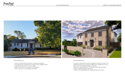
2507 EXPOSITION BLVDCURRENT & PROPOSED RESIDENCEExisting Residence> Lack of notable historic features or defining character> Vinyl siding and materials not congruent with neighborhood> Small home size for lot / owner’s value> Difficult back out of driveway onto Exposition > Narrow access to rear garage & parkingProposed Residence> A nod to Colonial Revival style, aligning w/various homes in the neighborhood & accounting for reference to residences in Tarry-town, NY as the neighborhood was named.> Elevated material quality with masonry & lap siding finishes> Historic inspired details & elements> Sized more appropriately for neighborhood and value TARRYTOWN RESIDENCE VICINITY MAP 2507 EXPOSITION BLVD AUSTIN, TEXAS 78703 NEW BUILD - TWO UNIT RESIDENCE AREA MAP ABBREVIATIONS SYMBOLS PROJECT INFORMATION DEVELOPMENT INFORMATION 3/4" DIMENSION XXX-## FINISH TAG PROJECT DESCRIPTION: See A1.00 Site Plan This is a new build two-story wood framed two unit residence which has a primary house "A unit" and a "B unit" which sits over the A unit garage. The site will utilize an existing second curb cut to create a circular drive. A cmu clad wall and get will be added along the property line near the street. The rear of the property will have improvements such as a covered patio w/grill counter, pool and edged artificial turf lawn. PROJECT AREAS: See A1.00 Site Plan SITE DATA: Address: Zoning: Land Use: FEMA Floodplain: Existing Site Plan: BUILDING USE: No. of Stories: Use: Construction Type: Existing Use: CODE & JURISDICTION Regulatory Jurisdiction: Applicable Codes: 2507 Expostiion Blvd SF-3-NP Residential NA NA 2 Duplex - 2 Unit VB Residence City of Austin City of Austin LDC CoA Amendments to IRC 2021 IRC 2021 above ABV adjacent ADJ above finished floor AFF alternate ALT approximately ~ architect ARCH at @ building BLDG bottom of BO construction CONST centerline CL ceiling CLNG concrete masonry unit CMU diameter Ø DN down DET/DTL detail equal EQ existing to remain ETR existing EXTG floor drain FD finished floor FF face of finish FOF face of stud FOS gypsum wall board GWB high point HP heating, ventilation HVAC + air conditioning ID MAX NIC NTS OC OD OFCI OFOI RCP REV RM RO SIM TBB TBD TO TYP UC UON VIF WP inside dimension maximum not in contract not to scale on center outside dimension owner furnished contractor installed owner furnished owner installed reflected ceiling plan revision room rough opening similar tile backer board to be determined top of typical under counter unless otherwise noted verify in field waterproofing ENTRY - 100 XX' x XX' ROOM NAME DIMS / CLNG HGHT REVISION 01 ## AX.XX E # P # A # EQUIPMENT TAG PLUMBING TAG ACCESSORY TAG AX.XX PARTITION TAG DETAIL TAG BUILDING ELEVATION BUILDING SECTION ## AX.XX ## AX.XX # # # AX.XX # INTERIOR ELEVATION TAG ## +100'-0" RECESS DEPTH SPOT ELEVATION 20 DOOR TAG ### A # WINDOW TAG PROJECT CONTACTS Architect: Page Paul Architecture Attn: Jeremy Olbrys RA 3409 Executive Center Drive Ste 100 Austin, TX 78731 jeremy@pagepaularchitecture.com 512.777.0147 Client: James & Sarah Cain 2507 Exposition Blvd Austin, TX 78703 james.cain@gmail.com Structural: Green Earth Engineering, Inc. 2500 W. William Cannon Dr Suite 201 Austin, TX 78745 Attn: Tim Zhang, P.E., LEED AP tzhang@ge-eng.com 512.289.8086 Contractor: 4 2 0 2 . 0 1 . 1 0 - T E S E C R P M L E R P I I 4 2 0 2 . 3 0 . 4 0 - T E S T I M R E P INDEX OF DRAWINGS ARCHITECTURE A0.00 A0.01 A0.02 A0.03 A0.04 A0.05 A0.06 A0.07 A1.00D A1.00 A1.01 A1.02 A1.10 A1.20 A1.30 A2.10 A2.11 A2.12 A2.20 A2.21 A2.30 A2.31 A2.32 A3.00 A3.01 A3.02 A4.00 A4.01 A4.10 A5.00 A6.00 A6.01 A6.02 A6.03 A7.00 A8.00 A8.01 A9.00 A9.01 A9.02 Coversheet Outline Specifications Finish & Fixtures Outline Specs General Requirements General Requirements General Requirements Tree Protections Visitable Route Plan Demo Site Plan Site Plan Site Plan Enlarged Plans Foundation Plan First Floor Plan Second Floor Plan Roof Plan Light Fixture Schedule First Floor RCP Second Floor RCP First Floor Power Plan Second Floor Power Plan Finish Schedule First Floor Finish Plan Second Floor Finish Plan First Floor Enlarged Plans First Floor Enlarged Plans Second Floor Enlarged Plans Exterior Elevations Exterior Elevations Building Sections Exterior Details Interior Elevations Interior Elevations Interior Elevations Interior Elevations Interior Details Door Schedule Window Schedule 3D Images 3D Images 3D Images STRUCTURAL S100 S200 S300 S301 S302 S303 S400 Foundation Plan Details 2nd Floor/Lower Roof Framing Plan Roof Framing Plan 1st Floor Wall Bracing Plan 2nd Floor Wall Bracing Plan Details I S R O R E T N I & E R U T C E T I H C R A 0 0 1 e t i u S 7 4 1 0 . 7 7 7 . 2 1 5 1 3 7 8 7 X T , n i t s u A e v i r D r e t n e C e v i t u c e x E 9 0 4 3 Architect Consultant Project e c n e d i s e R n w o t y r r a T l d v B n o i t i s o p x E 7 0 5 2 3 0 7 8 7 s a x e T , n i t s u A Seal e c n e d i s e R t i n U o w T d l i u B w e N Current Set: Permit Set 01.10.2024 PRELIM PRICING SET 04.03.2024 PERMIT SET Coversheet Title Sheet A0.00 This drawing and all copyright therein are the sole and exclusive property of Page Paul Architecture. Reproduction or use of this drawing without prior written consent of Page Paul Architecture is strictly prohibited. Copyright © 2023 Page Paul Architecture AREA DESCRIPTION EXTG SF TOTAL SF 10,145.00 SURVEY SITE PLAN BASED ON SURVEY PERFORMED BY WATERLOO SURVEYORS ON 06/16/2023 200 SF EXEMPTION PER 3.3.2.B ARTICLE 3 SUBCHAPTER F GFA EXEMPTION FROM 3.3.3.A ARTICLE 3 SUBCHAPTER F LEGEND TARRYTOWN DUPLEX - SITE PLAN LOT SIZE SF FLOOR 1 COND. AREA - UNIT A FLOOR 2 COND. AREA - UNIT A FLOOR 2 - UNIT B ATTACHED GARAGE COVERED PATIO/DECK/PORCH FLOOR 2 PORCH DRIVEWAY SIDEWALKS UNCOVERED PATIO UNCOVERED WOOD DECK CONCRETE FLATWORK (AC PADS) OTHER (POOL COPING, WALLS) NEW / ADDED SF 1,867.00 1,477.00 478.00 527.00 653.00 52.00 1,158.00 137.00 0.00 0.00 34.00 154.00 0.00 0.00 0.00 0.00 0.00 0.00 0.00 0.00 0.00 0.00 0.00 0.00 1,867.00 1,477.00 478.00 527.00 653.00 52.00 1,158.00 137.00 0.00 0.00 34.00 154.00 TOTAL BUILDING AREA SF TOTAL BUILDING COVERAGE SF 30.0% 5,054.00 3,047.00 4,058.00 ALLOWED (40%) 1,011.00 REMAINING TOTAL IMPERVIOUS COVERAGE SF 44.7% 4,530.00 4,565.25 ALLOWED (45%) 35.25 REMAINING W/DRIVEWAY STRIPS REMOVED (86SF) POOL 0.00 640.00 640.00 SUBCHAPTER F FLOOR-TO-AREA RATIO (FAR) 41.41% 4,201.00 5,579.75 ALLOWED (55%) (NEW CODE) 1,378.75 REMAINING WOOD FENCE CHAIN LINK FENCE - TREE FENCING WROUGHT IRON FENCE A/C UNIT ELEC. METER GAS METER WATER METER NEW BUILDING 1/2 CRZ 1/4 CRZ FULL CRZ 2" X 4" X 8' PLANKING ATTACHED TO THE TRUNK OF PROTECTED TREE WOOD CHIP MULCH AREA (8" DEPTH) 38'-1 7/8" CORNER OF SLAB LANDSCAPE BY OTHERS OVERHEAD ELECTRICAL LINE TREE LIST #70, 39" Elm #73, 10" Cypress #111, 19" Elm #142, 10" Mulbery #143, 18.5" Ligustrum #147, 12" Crepe Myrtle #148, 12" Moss Oak * NOTED TREES SHALL REQUIRE PROTECTION AS DESCRIBED A. B. C. TREE PROTECTION NOTES FULL CRZ AREA FOR EACH PROTECTED TREE SHOULD BE PROTECTED WITH A 5' TALL CHAIN LINK FENCE. E. NO PORTABLE TOILET, CONCRETE WASHOUT OR PAINT WASHOUT SHALL OCCUR WITHIN THE FULL CRZ OF PROTECTED TREES. IF FULL CRZ CANNOT BE FENCED, 1/2 CRZ SHOULD RECEIVE CHAIN LINK FENCE. 8" OF HARDWOOD MULCH SHOULD BE PLACED FROM THE 1/2 CRZ TO THE FULL CRZ. F. ANY DEMOLITION WITHIN THE 1/2 CRZ MUST BE PERFORMED BY HAND OR USING THE SMALLEST MACHINERY POSSIBLE TO MINIMIZE IMPACT. IF 1/2 CRZ CANNOT BE FENCED, 2x4 OR 2x6 OR GREATER LUMBER SHOULD BE VERTICALLY STRAPPED AROUND THE TREE. 8" OF HARDWOOD MULCH SHOULD BE PLACED IN ENTIRE CRZ. G. PRUNING MUST BE DONE BY AN ISA CERTIFIED ARBORIST AND CANNOT EXCEED 25% OF THE CANOPY. D. NO ACCESS ROUTE, MATERIAL STAGING, DUMPSTER OR SPOILS PLACEMENT SHALL OCCUR WITHIN THE 1/2 CRZ OF PROTECTED TREES. H. ANY NEW UTILITY TRENCH SHALL AVOID 1/2 CRITICAL ROOT ZONES OF PROTECTED TREES. IF 1/2 CRZ OF PROTECTED TREES CANNOT BE AVOIDED, THE TRENCHES SHALL BE AIR SPADED BY A QUALIFIED ARBORIST FOR THE TOP 30" TO AVOID CUTTING ROOTS > 1.5" IN DIAMETER. SITE PLAN GENERAL NOTES 1. 2. 3. 4. 5. 6. The dimensions on this sheet are to face of finish on existing walls, stud face for new walls, centerline of column/beam, and face of awning on new elements and face of existing finish. GC to field verify all dimensions prior to construction and/or installation of any equipment, accessories, etc. If a discrepancy is identified, please notify PPA immediately. Keynotes located on this sheet are for this sheet only. Do not scale the drawings. If a specific dimension is not given, contact PPA for clarification. Refer to General Requirements for additional information associated with, but not limited to: submittals, shop drawings, samples, cutting and patching, coordination and staging, protection of work. Install all products per manufacturer's recommendations. POST MOUNTED RACK W/NEW ELECTRIC METERS AND PANEL AS REQUIRED. CONNECTION RUN UNDERGROUND TO HOUSE. PRIMED & PAINTED STEEL STRINGER STAIR W/PRECAST CONCRETE TREADS. STAIR DESIGN & ENGINEERING TO BE COMPLETED BY FABRICATOR. FENCE TO BE MIN 5' TALL CHAIN LINK AND SUPPORTED ON STEEL T-POSTS WITH A MAXIMUM SPACING OF 10' BETWEEN POSTS. 8" DEEP WOOD CHIP MULCH PER CITY CODE, SHOWN HATCHED. S 60°00'04" E 135.64' #73 EM +609'-3" UP STAIR TRASH AC AC 1 A4.01 5' B.L. COA . Q E L O O P GARAGE 527 SF F.F.E. VARIES UNIT B (ABOVE) 481 COND. SF +610'-1 1/4" GRILL +610'-0 1/2" UP TURF 269 SF Project TREE TO HAVE 2X4 BOARD WRAP AT 6' HEIGHT MINIMUM, PER CoA WATERSHED PROTECTION DEPARTMENT STANDARDS 2" / Z R #111 C Q 2'-4 1 R R 4'- 9 " H C R Z R 9 ' - 6 " F U L L C R Z " 0 - ' 2 1 " 4 / 3 9 - ' 7 4 " 0 - ' 2 1 PAVED DRIVEWAY EXISTING CURB CUT CURRENT WATER METER LOCATION (APPROX.) PROPOSED LOCATION OF NEW WATER METER, IN PUBLIC R.O.W. E x p o s i t i o n B v d l LANDSCAPE BY OTHERS VARIOUS HEIGHT PRIVACY WALL WITH LEVEL TOP AND METAL GATE. MAXIMUM HEIGHT TO NOT EXCEED 6FT. WALL TO BE BUILT OF CMU BLOCK W/CLADDING PER ELEVATIONS FRONT PORCH & SIDE WALLS FENCE TO BE MIN 5' TALL CHAIN LINK AND SUPPORTED ON STEEL T-POSTS WITH A MAXIMUM SPACING OF 10' BETWEEN POSTS. APPROXIMATE LOCATION OF EXISTING WASTEWATER LINE AND CONNECTION EXISTING CURB CUT ALL TREES AT SIZE OF 19" DIAMETER @ 4.5' UP FROM GRADE TO BE PROTECTED PER DETAILS AND NOTES ON A0.04 SITE PLAN SCALE: 1/8" = 1'-0" @ 22X34 . S . O C . " 8 / 7 0 1 - ' 9 DRIVE 1,158 SF WATER LINE 1 5 ' B . L . C O A 12'-0" 2 A4.00 LP 609.25' SLOPE " 4 / 3 1 1 - ' 7 1 2 5 ' B . L . C O A PORTABLE TOILET w SPOILS ' N 2 9 ° 5 5 0 0 " E 7 4 . 9 9 ' WASTEWATER LINE G . . . C W B " 8 / 5 6 - ' 9 R 9 '- 5 7 / 8 " H C R Z R 1 9 ' - 6 " F U L L C R Z R4'-8 7/8" QCRZ #70 30'-9 3/8" BRICK WALL CORNER MATERIALS STAGING +611'-8" UP UNIT A/ TWO STORY RESIDENCE 3,341 COND. SF 611.75' F.F.E. (611'-9") 5 ' B . L . C O A 4 / 1 3 8 3 ' . P U . E . S 2 9 ° 5 4 0 1 " ' W 7 4 . 6 0 ' 2 A4.01 #148 PATIO 650 SF +611'-8" +611'-8" POOL & SPA 20' x32' PATIO ROOF ABOVE HP 611.02' 1 A4.00 5' B.L. COA #142 #143 #147 N 60°10'00" W 135.66' I S R O R E T N I & E R U T C E T I H C R A 0 0 1 e t i u S 7 4 1 0 . 7 7 7 . 2 1 5 1 3 7 8 7 X T , n i t s u A e v i r D r e t n e C e v i t u c e x E 9 0 4 3 Architect Consultant e c n e d i s e R n w o t y r r a T l d v B n o i t i s o p x E 7 0 5 2 3 0 7 8 7 s a x e T , n i t s u A Seal e c n e d i s e R t i n U o w T d l i u B w e N Current Set: Permit Set 01.10.2024 PRELIM PRICING SET 04.03.2024 PERMIT SET Site Plan Title Sheet A1.00 This drawing and all copyright therein are the sole and exclusive property of Page Paul Architecture. Reproduction or use of this drawing without prior written consent of Page Paul Architecture is strictly prohibited. Copyright © 2023 Page Paul Architecture 1 EXTERIOR STAIR, RAILING & HANDRAIL TO BE COMPLIANT W/IRC & CoA CODE. STAIR TO BE DESIGNED AND FABRICATED WITH OTHER PARTY DURING CONSTRUCITON 1 A3.00 UP +610'-2" +610'-1 1/4" 23'-0" 12'-5 1/8" WALL HATCH LEGEND FLOOR PLAN GENERAL NOTES Architect NEW WALL (2X6 @ EXT. WALLS, WET WALLS & POCKET DOORS) NEW WALL (2X4 @ INT. WALLS U.N.O.) 1. 2. 3. 4. 5. 6. The dimensions on this sheet are to face of finish on existing walls, stud face for new walls, centerline of column/beam, and face of awning on new elements and face of existing finish. GC to field verify all dimensions prior to construction and/or installation of any equipment, accessories, etc. If a discrepancy is identified, please notify PPA immediately. Keynotes located on this sheet are for this sheet only. Do not scale the drawings. If a specific dimension is not given, contact PPA for clarification. Refer to General Requirements for additional information associated with, but not limited to: submittals, shop drawings, samples, cutting and patching, coordination and staging, protection of work. Install all products per manufacturer's recommendations. I S R O R E T N I & E R U T C E T I H C R A 0 0 1 e t i u S 7 4 1 0 . 7 7 7 . 2 1 5 1 3 7 8 7 X T , n i t s u A e v i r D r e t n e C e v i t u c e x E 9 0 4 3 EXTERIOR HOUSE SPIGOT PRODUCT AQUOR HOUSE HYDRANT V2+ SLATE GRAY POLYMER ## AX.XX Consultant 1 A4.01 +610'-5" 3'-0" E P O L S 2 ! : 1 WOOD FRAMED PLYWOOD TOPPED VISITABILITY RAMP LAUNDRY 11'-11" x 6'-2" 3 A3.00 WASHER DRYER " 8 / 5 8 - ' 4 04 " 4 / 1 7 - ' 2 2 " 4 / 1 7 - ' 1 1 " 8 - ' 1 1 " 8 / 3 4 - ' 8 5 " 4 / 1 4 - ' 1 " 0 - ' 9 " 4 / 1 4 - ' 1 " 8 - ' 1 1 " 8 / 1 5 - ' 3 " 4 / 3 1 - ' 6 " 4 / 3 1 - ' 6 02 GARAGE 22' x 22' SLIGHT SLOPE " 0 - ' 5 1 8'-7 5/8" 7'-9" 3'-1 3/4" 03 PANTRY 4'-9" x 6'-2" " 4 / 3 0 - ' 4 UP +611'-8" 07 A6.01 10 09 9 08 A6.01 8 MUD +611'-9" FFE " 2 / 1 0 - ' 2 UP 3 A3.01 1 A6.02 10 3'-0" 2'-6 1/2" 03 POWDER 5'-5" x 6'-0" WET BAR 7'-5" x 6'-2" 1'-9 1/2" 1'-2 3/8" 6 A6.01 1 KITCHEN 18'-3" x 15'-7" 2 7 SKYLIGHT ABOVE 2 A4.01 INTERIOR STAIR, RAILING & HANDRAIL TO BE COMPLIANT W/IRC & CoA CODE. RISERS EQ. @ APPROX 7.3". TREADS @11 1/2" DEEP. RAILINGS @ 36" HIGH WITH OPENINGS NO LARGER THAN 4" IN DIAMETER ENTRY 1 +611'-9" FFE A6.00 UP 13 2 CLOSET UNDER STAIR 02 A3.00 2'-11 1/2" 2'-6" 5 A6.01 4 2'-0 1/4" 02 END OF WALL CASING TO BE PROUD OF TREAD RISER 3 A6.00 5 DINING 15' x 11'-4" 4 6 LINE OF FLOOR OPENING ABOVE 5'-11 3/8" 2 A4.00 " 8 - ' 2 " 0 - ' 3 " 2 / 1 0 1 06 12 " 8 / 5 8 " 8 / 1 3 - ' 1 3 " 1 - ' 7 " 4 / 3 1 1 - ' 1 BUILT-IN MILLWORK 5 A6.02 STUDY 8'-1" x 14'-9" 6 7 07 01 01 01 10 6'-7 1/8" 9 BED 1 13'-2" x 11'-2" 8 A6.02 10 11 M P T R R O A O D D D E E U N L C N A U T M M E B E R 14 " 2 / 1 9 - ' 4 BATH 1 5' x 11'-1" A6.02 12 09 3'-1 3/4" EXTERIOR HOUSE SPIGOT PRODUCT AQUOR HOUSE HYDRANT V2+ SLATE GRAY POLYMER R E B E M M U T L A C N A N L U R E E D E D D T O O A A R R M M P T I 08 1'-6 7/8" GROUND FLOOR PLAN SCALE: 1/4" = 1'-0" @ 22x34 04 A3.00 05 PATIO 8'-0 1/4" 3'-4 1/2" +611'-8" 04 2 A3.01 11 LIVING 21'-8" x 19'-2" 2 A6.02 4 3 " 3 - ' 8 BUILT-IN MILLWORK " 2 / 1 1 - ' 2 06 ## AX.XX 05 5'-4 1/2" 2'-6" 3'-3 1/2" 7'-2 1/2" 7'-4 1/2" 21'-6 1/4" 2'-1 1/2" 1 A4.00 1 A3.01 6'-6 7/8" 52'-5 1/8" 48" GAS FIREPLACE 7'-7 1/2" 22'-2 1/2" LOCATION OF SHAFT ABOVE. GC TO ARRANGE MEETING WITH ARCHITECT & MECHANICAL SUB TO DETERMINE NEEDS & OPTIONS. " 4 / 3 6 - ' 7 ## AX.XX FAUX WOOD BEAMS ABOVE, SEE RCP. LINE OF SECOND FLOOR OVERHANG ABOVE 6x6 PRE-DRIED CEDAR COLUMN W/METAL SIMPSON BASE. COLUMN CLAD W/3/4" SUBSTRATE & 3/4" SMOOTH CEMENT BOARD TRIM WRAP OUTDOOR STORAGE " 4 / 1 2 - ' 5 " 4 / 3 1 1 - ' 2 3 " 4 / 1 2 - ' 0 2 " 0 - ' 7 " 4 - ' 6 " 2 / 1 6 - ' 4 " 4 / 1 1 - ' 5 1 " 4 / 3 2 - ' 6 " 4 / 3 5 - ' 7 " 4 / 1 4 - ' 8 5 1 Project e c n e d i s e R n w o t y r r a T l d v B n o i t i s o p x E 7 0 5 2 3 0 7 8 7 s a x e T , n i t s u A Seal e c n e d i s e R t i n U o w T d l i u B w e N Current Set: Permit Set 01.10.2024 PRELIM PRICING SET 04.03.2024 PERMIT SET Title Ground Floor Plan Sheet A1.10 This drawing and all copyright therein are the sole and exclusive property of Page Paul Architecture. Reproduction or use of this drawing without prior written consent of Page Paul Architecture is strictly prohibited. Copyright © 2023 Page Paul Architecture BRICK / MYS-1 6'-10 7/8" 23'-0 1/8" 3'-6 1/2" WALL HATCH LEGEND FLOOR PLAN GENERAL NOTES Architect 1HR RATED WALL ASSEMBLY BETWEEN UNITS BASED ON DESIGN #GA WP 3370 ADDED 5/8" DRYWALL FINISH WITH GREEN GLUE BETWEEN FOR ADDED ACOUSTIC PERFORMANCE. INSTALL PANELS & GLUE PER MANUFACTURER'S INSTRUCTIONS. 11'-4 1/2" 1 A3.00 1 A4.01 5'-9 7/8" NEW WALL (2X6 @ EXT. WALLS, WET WALLS & POCKET DOORS) NEW WALL (2X4 @ INT. WALLS U.N.O.) 1. 2. 3. 4. 5. 6. The dimensions on this sheet are to face of finish on existing walls, stud face for new walls, centerline of column/beam, and face of awning on new elements and face of existing finish. GC to field verify all dimensions prior to construction and/or installation of any equipment, accessories, etc. If a discrepancy is identified, please notify PPA immediately. Keynotes located on this sheet are for this sheet only. Do not scale the drawings. If a specific dimension is not given, contact PPA for clarification. Refer to General Requirements for additional information associated with, but not limited to: submittals, shop drawings, samples, cutting and patching, coordination and staging, protection of work. Install all products per manufacturer's recommendations. PEDESTAL PAVER TOPPING MEMBRANE BELOW. MEMBRANE SURFACE SLOPED TO SCUPPER THROUGH WALL SCUPPER I S R O R E T N I & E R U T C E T I H C R A 0 0 1 e t i u S 7 4 1 0 . 7 7 7 . 2 1 5 1 3 7 8 7 X T , n i t s u A e v i r D r e t n e C e v i t u c e x E 9 0 4 3 Consultant PATIO ROOF BELOW ## AX.XX 1HR FIRE RATING WALL SCALE: 3/4" = 1'-0" @ 22x34 2 ADDITIONAL ROCKWOOL BATT INSULATION ASSEMBLY WALL REQUIREMENTS - GYPSUM PANELS: ONE LAYER 5/8" SHEETROCK ECOSMART GYPSUM PANEL - WOOD STUDS: 2"X4" @ 16" O.C. AIR SPACE: 1" AIR SPACE - - WOOD STUDS: 2"X4" @ 16" O.C. - - INSULATION: 3-1/2" FIBERGLASS INSULATION GYPSUM PANELS: ONE LAYER 5/8" SHEETROCK ECOSMART GYPSUM PANEL SLIGHT SLOPE UNDER 27 DN PORCH 10'-7" x 4' 17 BED B 10'-9" x 9'-2" 7'-7 1/2" 29 LIVING B 10'-10" x 12'-9" A6.05 11 " 4 / 1 1 - ' 8 2'-3 1/2" 28 A6.05 12 W/D 13 KITCHEN B 10'-10" x 9'-0" 16 15 14 4 A3.02 3'-1 3/4" 13 1HR RATING WALL BETWEEN UNITS, ACOUSTIC ASSEMBLY PER OUTLINE SPECS FRIDGE 30 A6.05 14 18 I L A R E T A M T C U D O R P M T R O A D D E E N L N A U M M E B E R BATH B 10'-9" x 5' M DW 15 T C U D O R P E M A N E D A R T MODELNUMBER " 6 - ' 4 " 6 - ' 6 " 6 - ' 6 " 4 / 1 7 - ' 2 2 " 4 - ' 2 3 " 2 / 1 4 - ' 8 " 0 - ' 4 " 4 / 3 1 - ' 6 " 2 / 1 1 - ' 2 1 " 4 / 3 1 - ' 6 " 0 1 - ' 1 1 2 A4.00 LINE OF ENTRY ROOF BELOW " 4 / 3 2 - ' 2 P R O D U C T M T R O A D D E E N L N A U M M E B E R R E B E M M U T A C N N L U E E D D D O O A R R M P T MODELNUMBER MATERIAL TRADENAME PRODUCT 4 6 7 9 26 23 MODELNUMBER MATERIAL TRADENAME PRODUCT 24 3 A3.02 1'-4 3/8" 2 A1.20 A6.03 2 25 BED 2 13'-0"' x 11'-3" 1'-9" 1'-9" 3 A6.03 5 7 A6.03 10 19 FLEX 11' x 11'-2" " 4 / 3 5 - ' 1 8 9 9'-10 7/8" 15 SKYLIGHT ABOVE DN 31 1 A6.03 BATH 3 5'-0" x 11'-3" 1 A3.00 BATH 2 5'-0" x 11'-3" LAUNDRY CHUTE 16 2'-8 7/8" 5'-0" LINE OF FIRST FLOOR EXTERIOR WALL BELOW ROOF LINEN CLOSET W/FIXED SHELVING MECHANICAL SHAFT, SIZING & SPECIFICS TBD W/MECHANICAL CONTRACTOR, GC & ARCHITECT 2 A4.01 20 ## AX.XX BED 3 13'-0" x 11'-3" A6.05 10 22 6 A6.05 8 " 2 / 1 6 - ' 3 17 20 P. CLOSET 10'-7" x 7' " 8 - ' 7 21 1 A6.04 3 ## AX.XX 2 4 M A T E R A L I M P T R R O A O D D D E E U N L C N A U T M M E B E R I L A R E T A M R E B E M M U T A C N N L U E E D D D O O A R R M P T 19 " 1 - ' 3 18 P. BATH 174 SQ.FT. PRIMARY BED 12' x 19'-1" 12 11 26 . Q E . Q E 24 21 25 " 1 1 - ' 5 " 7 - ' 3 " 1 1 - ' 5 " 4 - ' 2 3'-1 3/4" 2'-6 1/2" 5'-5 1/4" 6'-0" 5'-5 3/8" 4'-8 1/2" 2'-2" 1 A4.00 21'-6 1/4" 2 A3.02 23 3 5/8" 52'-4 5/8" 22 1 A3.02 2'-3 1/2" 3'-9 3/8" 30'-10 3/8" SECOND FLOOR PLAN SCALE: 1/4" = 1'-0" @ 22x34 1 " 4 / 3 7 - ' 4 " 2 / 1 1 1 - ' 7 1 " 2 - ' 0 2 " 4 / 1 4 - ' 8 5 " 7 - ' 5 1 " 2 / 1 8 - ' 9 " 2 / 1 6 - ' 2 " 0 1 - ' 1 " 4 / 3 0 - ' 6 " 4 / 3 1 - ' 3 " 1 - ' 9 " 4 / 3 3 - ' 3 Project e c n e d i s e R n w o t y r r a T l d v B n o i t i s o p x E 7 0 5 2 3 0 7 8 7 s a x e T , n i t s u A Seal e c n e d i s e R t i n U o w T d l i u B w e N Current Set: Permit Set 01.10.2024 PRELIM PRICING SET 04.03.2024 PERMIT SET Title Second Floor Plan Sheet A1.20 This drawing and all copyright therein are the sole and exclusive property of Page Paul Architecture. Reproduction or use of this drawing without prior written consent of Page Paul Architecture is strictly prohibited. Copyright © 2023 Page Paul Architecture T.O. RIDGE (APPROX) + 29'- 4 1/14" I E N L Y T R E P O R P K C A B T E S ' 5 T.O. DBL PLTE (104 5/8" STD) + 20'- 7 3/8" T.O. DBL P UNIT B (104 5/8" STD) + 19''- 4 1/8" FIBER CEMENT LAP SIDING W/NARROWER EXPOSURE AT SECOND LEVEL, TYP. PAINTED STEEL STRINGER STAIR AND TREAD PANS W/CONCRETE TREADS BETWEEN. STAIR DESIGN AND SHOPS BY OTHERS. T.O.F.F. +11'- 7 3/4" T.O. TRUSS + 11'- 5 1/8" T.O. F.F. UNIT B + 10'- 3 3/4" T.O. TRUSS GARAGE + 10'- 1 7/8" T.O. DBL PLTE (116 5/8" STD) + 10'- 1 1/8" T.O. DBL PLTE GARAGE + 8' -9 7/8" T.O.F.F. +1'-4" T.O. SLAB + 0'-0" T.O. SLAB GARAGE (BACK FLAT) - 1'-3 1/4" TRIM BAND CREATED W/VARIOUS TRIM PIECES. SEE DETAIL. PRE-FINISHED HALF ROUND GUTTER W/ROUND DOWNSPOUTS 12 6 WEST ELEVATION SCALE: 1/4" = 1'-0" @ 22x34 T.O. RIDGE (APPROX) + 29'- 4 1/14" T.O. DBL PLTE (104 5/8" STD) + 20'- 7 3/8" T.O. DBL P UNIT B (104 5/8" STD) + 19''- 4 1/8" T.O.F.F. +11'- 7" T.O. TRUSS + 11'- 5 1/8" T.O. F.F. UNIT B + 10'- 3 3/4" T.O. TRUSS GARAGE + 10'- 1 7/8" T.O. DBL PLTE (116 5/8" STD) + 10'- 1 1/8" T.O. DBL PLTE GARAGE + 8' -9 7/8" T.O.F.F. +1'-4" T.O. SLAB + 0'-0" T.O. SLAB GARAGE (BACK FLAT) - 1'-3 1/4" MSY-2 RF-1 FC-3 MSY-1 MSY-2 ST-10 MSY-2 SOUTH ELEVATION SCALE: 1/4" = 1'-0" @ 22x34 25 09 16 15 14 TRIM BAND CREATED W/VARIOUS TRIM PIECES. SEE DETAIL. LIGHT FIXTURE PER SCHEDULE " 0 - ' 7 02 11 01 01 12 02 H C R A / W M R F N O C I 26 10 RF-2 MSY-1 MSY-2 RECESS IN FACADE CREATED BY USING THIN BRICK SECURED TO SHEATHING PREFINISHED ROUND DOWNSPOUTS. MSY-2 ST-10 HORIZONTAL JOINT AT BRICK WHERE FULL SIZE BRICK MEETS THIN BRICK. CUT THIN BRICKS TO MAKE COURSING LOOK CONTINUOUS. FUR OUT EXTERIOR WALL SO BRICK FACES ALIGN. 12 6 23 22 24 08 RF-1 FC-3 TYP. FC-2 TYP. FIBER CEMENT LAP SIDING W/NARROWER EXPOSURE AT SECOND LEVEL, TYP. PAINTED TRIM RF-2 LOW SLOPED TPO ROOFING MEMBRANE COLUMN W/PTD TRIM WRAP FC-1 TYP. FC-3 MT-1 TYP. 07 OPEN STORAGE ACCESS DOOR BRICK LUG AT GRADE STEP AS NECESSARY RECESS IN FACADE CREATED BY USING THIN BRICK SECURED TO SHEATHING VENT FOR GAS FIREPLACE DOWNSPOUTS AT PATIO COLUMNS TO CONNECT TO PVC PIPE CAST INTO FOUNDATION & DRAWING TO DAYLIGHT @ LOWER GRADE I E N L Y T R E P O R P K C A B T E S ' 5 RF-1 FC-3 RF-1 EXTERIOR ELEV GENERAL NOTES Architect 1. 2. 3. 4. 5. 6. 7. The dimensions on this sheet are to assumed face of finish on existing walls, stud face for new walls, centerline of column/beam, and face of awning on new elements and face of existing finish. Dimension strings typically fall to one side of stud wall in a continuous run and the outside face of any exterior walls. Refer to dimension string locations. GC to field verify all dimensions prior to construction and/or installation of any equipment, accessories, etc. If a discrepancy is identified, please notify PPA immediately. Keynotes located on this sheet are for this sheet only. Do not scale the drawings. If a specific dimension is not given, contact PPA for clarification. Refer to General Requirements for additional information associated with, but not limited to: submittals, shop drawings, samples, cutting and patching, coordination and staging, protection of work. Install all products per manufacturer's recommendations. Drawn objects & products may not reflect final selections to be installed. Refer to specifications. GC to contact PPA for any discrepancies or needed clarifications. Consultant I S R O R E T N I & E R U T C E T I H C R A 0 0 1 e t i u S 7 4 1 0 . 7 7 7 . 2 1 5 1 3 7 8 7 X T , n i t s u A e v i r D r e t n e C e v i t u c e x E 9 0 4 3 Project e c n e d i s e R n w o t y r r a T l d v B n o i t i s o p x E 7 0 5 2 3 0 7 8 7 s a x e T , n i t s u A Seal e c n e d i s e R t i n U o w T d l i u B w e N 2 Current Set: Permit Set 01.10.2024 PRELIM PRICING SET 04.03.2024 PERMIT SET Title Exterior Elevations Sheet A4.00 1 This drawing and all copyright therein are the sole and exclusive property of Page Paul Architecture. Reproduction or use of this drawing without prior written consent of Page Paul Architecture is strictly prohibited. Copyright © 2023 Page Paul Architecture FIXED CURB MOUNTED SKYLIGHT WITH OPERABLE LIGHT FILTERING SHADE, VELUX FCM K C A B T E S ' 5 12 6 I E N L Y T R E P O R P FC-3 RF-1 FC-2 12 6 PREFINISHED STANDING SEAM METAL ROOF PER SPECIFICATIONS, TYP. K C A B T E S ' 5 RF-1 I E N L Y T R E P O R P 21 19 18 OPEN 27 RF-2 STORAGE DOORS CLAD TO MATCH W/SIDING AND TO HAVE NO SURROUND TRIM 05 06 03 05 04 DOWNSPOUTS AT PATIO COLUMNS TO CONNECT TO PVC PIPE CAST INTO FOUNDATION & DRAWING TO DAYLIGHT @ LOWER GRADE RF-1 FC-2 INTEGRAL METAL FLASHED FIXED SKYLIGHT W/LIGHT FILTERING SHADE, VELUX QPF LOW SLOPED TPO ROOFING MEMBRANE 20 FIXED CURB MOUNTED SKYLIGHT WITH OPERABLE LIGHT FILTERING SHADE, VELUX FCM MSY-2 FC-3 12 6 17 EAST ELEVATION SCALE: 1/4" = 1'-0" @ 22x34 T.O. RIDGE (APPROX) + 29'- 4 1/14" T.O. DBL PLTE (104 5/8" STD) + 20'- 7 3/8" T.O. DBL P UNIT B (104 5/8" STD) + 19''- 4 1/8" T.O.F.F. +11'- 7" T.O. TRUSS + 11'- 5 1/8" T.O. F.F. UNIT B + 10'- 3 3/4" T.O. TRUSS GARAGE + 10'- 1 7/8" T.O. DBL PLTE (116 5/8" STD) + 10'- 1 1/8" T.O. DBL PLTE GARAGE + 8' -9 7/8" T.O.F.F. +1'-4" T.O. SLAB + 0'-0" T.O. RIDGE (APPROX) + 29'- 4 1/14" T.O. DBL PLTE (104 5/8" STD) + 20'- 7 3/8" T.O. DBL P UNIT B (104 5/8" STD) + 19''- 4 1/8" T.O.F.F. +11'- 7" T.O. TRUSS + 11'- 5 1/8" T.O. F.F. UNIT B + 10'- 3 3/4" T.O. TRUSS GARAGE + 10'- 1 7/8" T.O. DBL PLTE (116 5/8" STD) + 10'- 1 1/8" T.O. DBL PLTE GARAGE + 8' -9 7/8" T.O.F.F. +1'-4" T.O. SLAB + 0'-0" T.O. SLAB GARAGE (BACK FLAT) - 1'-3 1/4" MSY-2 MSY-4 CON-2 OPEN MSY-4 MSY-2 CON-2 GRILL ELEVATION SCALE: 1/4" = 1'-0" @ 22x34 1.2 LOW SLOPED TPO ROOFING MEMBRANE. 1/4": 1'-0" SLOPE TYP. FC-3 EXTERIOR ELEV GENERAL NOTES Architect 1. 2. 3. 4. 5. 6. 7. The dimensions on this sheet are to assumed face of finish on existing walls, stud face for new walls, centerline of column/beam, and face of awning on new elements and face of existing finish. Dimension strings typically fall to one side of stud wall in a continuous run and the outside face of any exterior walls. Refer to dimension string locations. GC to field verify all dimensions prior to construction and/or installation of any equipment, accessories, etc. If a discrepancy is identified, please notify PPA immediately. Keynotes located on this sheet are for this sheet only. Do not scale the drawings. If a specific dimension is not given, contact PPA for clarification. Refer to General Requirements for additional information associated with, but not limited to: submittals, shop drawings, samples, cutting and patching, coordination and staging, protection of work. Install all products per manufacturer's recommendations. Drawn objects & products may not reflect final selections to be installed. Refer to specifications. GC to contact PPA for any discrepancies or needed clarifications. Consultant I S R O R E T N I & E R U T C E T I H C R A 0 0 1 e t i u S 7 4 1 0 . 7 7 7 . 2 1 5 1 3 7 8 7 X T , n i t s u A e v i r D r e t n e C e v i t u c e x E 9 0 4 3 FIBER CEMENT LAP SIDING W/NARROWER EXPOSURE. SECOND LEVEL, TYP. LOW SLOPED TPO ROOFING MEMBRANE. 1/4": 1'-0" SLOPE TYP. PAINTED STEEL STRINGER STAIR AND TREAD PANS W/CONCRETE TREADS BETWEEN. STAIR DESIGN AND SHOPS BY OTHERS. PREFINISHED METAL SCUPPER W/FLASHED EXTENSION Project PAINTED STEEL STRINGER STAIR W/PRECAST CONCRETE TREADS BETWEEN. OUTSIDE STRINGER TO HAVE 1 1/2" X 2" STEEL TUBE POSTS WELDED TO IT'S EXTERIOR, SPACED APPROX 4' O.C. STEEL TUBE POSTS TO BE CAPPED BY 1/4" THK 3" WIDE PTD STEEL FLAT BAR. ATTACHED OUTSIDE OF POSTS ARE PAINTED 3/4" X 3 1/2" FIBER CEMENT BOARDS, SPACED EQUALLY WITH GAPS AROUND 1 1/2". PAINTED 1" METAL PIPE HANDRAIL TO BE MOUNTED TO POSTS ON THE TREAD SIDE. STAIR DESIGN AND SHOPS BY OTHERS. e c n e d i s e R n w o t y r r a T l d v B n o i t i s o p x E 7 0 5 2 3 0 7 8 7 s a x e T , n i t s u A e c n e d i s e R t i n U o w T d l i u B w e N 2 PTD 2X6 VERTICAL SCREEN WALL MSY-2 FC-2 TYP. Seal 12 6 HORIZONTAL JOINT AT BRICK WHERE FULL SIZE BRICK MEETS THIN BRICK. CUT THIN BRICKS TO MAKE COURSING LOOK CONTINUOUS. FUR OUT EXTERIOR WALL SO BRICK FACES ALIGN. RF-1 MSY-1 MSY-2 MT-1 ST-10 1 BRICK MASONRY VENEER Current Set: Permit Set 01.10.2024 PRELIM PRICING SET 04.03.2024 PERMIT SET FIBER CEMENT LAP SIDING W/NARROWER EXPOSURE. SECOND LEVEL, TYP. 13 03 Title Exterior Elevations Sheet A4.01 This drawing and all copyright therein are the sole and exclusive property of Page Paul Architecture. Reproduction or use of this drawing without prior written consent of Page Paul Architecture is strictly prohibited. Copyright © 2023 Page Paul Architecture DOWNSPOUTS AT PATIO COLUMNS TO CONNECT TO PVC PIPE CAST INTO FOUNDATION & DRAWING TO DAYLIGHT @ LOWER GRADE OPEN 04 POOL EQ. AC. AC. BREEZE WALL ELEVATION SCALE: 1/4" = 1'-0" @ 22x34 PAVER EDGE 1.1 T.O. SLAB GARAGE (BACK FLAT) - 1'-3 1/4" BREEZE WALL HIDDEN SEE ELEVATION 1.1 @ A4.01 NORTH ELEVATION SCALE: 1/4" = 1'-0" @ 22x34 FIBER CEMENT LAP SIDING FC-1 TYP. PAINTED STEEL STRINGER STAIR W/PRECAST CONCRETE TREADS BETWEEN. OUTSIDE STRINGER TO HAVE 1 1/2" X 2" STEEL TUBE POSTS WELDED TO IT'S EXTERIOR, SPACED APPROX 4' O.C. STEEL TUBE POSTS TO BE CAPPED BY 1/4" THK 3" WIDE PTD STEEL FLAT BAR. ATTACHED OUTSIDE OF POSTS ARE PAINTED 3/4" X 3 1/2" FIBER CEMENT BOARDS, SPACED EQUALLY WITH GAPS AROUND 1 1/2". PAINTED 1" METAL PIPE HANDRAIL TO BE MOUNTED TO POSTS ON THE TREAD SIDE. STAIR DESIGN AND SHOPS BY OTHERS.