21.1 - 501 texas — original pdf
Backup
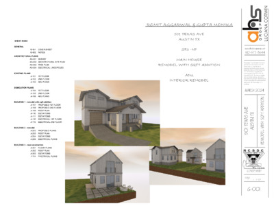
ROMIT AGGARWAL & GUPTA MONIKA 501 TEXAS AVE AUSTIN TX SF3 -NP MAIN HOUSE REMODEL WITH SQFT ADDITION ADU INTERIOR REMODEL SHEET INDEX GENERAL G-001 G-002 COVER SHEET NOTES ARCHITECTURAL PLANS AS-001 AS-002 AS-003 AS-004 SURVEY ARCHITECTURAL SITE PLAN TREE PLAN ELECTRICAL LINES/POLES EXISTING PLANS DEMOLITION PLANS A-101 A-102 A-103 1ST FLOOR 2ND FLOOR ADU PLANS A-104 A-105 A-106 1ST FLOOR 2ND FLOOR ADU PLANS BUILDING 1 - remodel with sqft addition A-107 A-108 A-109 A-110 A-111 A-112 A-113 PROPOSED 1ST FLOOR PROPOSED 2ND FLOOR ROOF PLAN ELEVATIONS ELEVATIONS ELECTRICAL 1ST FLOOR ELECTRICAL 2ND FLOOR BUILDING 2 - remodel BUILDING 3 - new construction A-203 A-205 A-204 A-206 PROPOSED PLANS ROOF PLAN ELEVATIONS ELECTRICAL PLANS A-301 A-302 A-303 A-304 FLOOR PLANS ROOF PLAN ELEVATIONS ELECTRICAL PLANS GENERAL CONDITIONS. 1. These documents comprise a portion of a contract between the Owner and the General Contractor. No contract is implied or stated between the Owner and any other party, nor between the Building Designer and any party. 2. No set of contract documents is able to contain all the information required to construct a project. Interpretation by the General Contractor is required. By use of these documents, both the Owner and the General Contractor assent to this understanding of the nature of contract documents. 3. The General Contractor is responsible for the provision of minor details and appurtenances not shown in the contract documents. 4. The General Contractor and his/her subcontractors are responsible for the final design of the HVAC, plumbing, and electrical systems. 5. The General Contractor may not revise or modify the contract documents, in whole or in part, without the prior approval of the Owner. Consultation with the Building Designer beforehand is strongly recommended. And precicely locate all the piping, fitting, offsets, bends, devices and equipments. 6. The General Contractor may not modify the plans, elevations, or site plan shown in the contract documents without obtaining Building Designer consultation and Owner approval beforehand. 7. Should the Owner request changes to the contract documents, the General Contractor is responsible for ensuring that the changes do not result in a built condition that does not comply with codes and/or regulations. Consultation with the Building Designer and/or an Inspector is highly recommended. 8. The Building Designer is not an inspector and is not liable for the General Contractor's failure to execute the Work in accordance with the contract documents and/or in conformance with any and/or all applicable codes, laws, statutes and regulations. 9. The Owner shall not be held liable nor be made to pay for the remediation of work judged substandard and/or rejected by the Building Designer, the Owner, and/or any Inspector (municipal or third-party). The Owner alone reserves the right to accept work judged substandard by either the Building Designer or the Owner. Should the Owner elect to accept substandard work, the Owner reserves the right to request monetary credit and/or a reduction in the contract sum. 10. The Owner and/or the Building Designer shall be permitted to access the project site, in part and as a whole, at any reasonable time without prior notice. If the project site, in part or as a whole, is locked or otherwise secured, the Building Designer shall coordinate with the General Contractor to gain access. Neither the Owner nor the General Contractor shall be held liable for the consequences of the Building Designer's presence onsite unless said consequences arise from an unsafe or otherwise substandard project condition. 11. The General Contractor is solely responsible for obtaining and maintaining all such bonding, sureties, and insurances such as may be required to shield the Owner from claims pertaining to the General Contractor's and/or Subcontractors' execution of the Work and their respective conduct onsite. 12. The General Contractor is solely responsible for ensuring that working conditions onsite are safe and comply with all relevant rules, laws, codes, and standards. Likewise, the General Contractor is solely responsible for ensuring that all personnel onsite conduct themselves in a safe and prudent manner at all times, whether or not the General Contractor is present. 13. In Case of discrepancies or comflicts on the drawings and specifications or between drawings and exosting conditions, contact the designer or owner before proceeding with the work. NOTES REGARDING CODES, REGULATIONS, STANDARDS, PERMITS and INSPECTIONS. 1. The General Contractor is responsible for ensuring built compliance with all codes, regulations, and standards such as may be in force. These codes include but may not be limited to: 2021 International Building Code - 2021 Edition 2021 International Residl Code for One- and Two-Family Dwellings 2021 International Energy Conservation Code 2021 International Mechanical Codentiae 2021 International Fire Code - 2021 Edition as amended by Travis County Emergency Service District No. 6 2021 International Gas Code 2021 National Electrical Code 2021 Uniform Plumbing Code 2021 International Existing Building Code 2021 International Property Maintenance Code 2. Should the General Contractor become aware of a condition shown or depicted in the contract documents that would result in a violation of any code or regulation listed above, the General Contractor shall contact the Building Designer immediately for resolution. 3. The General Contractor shall be responsible for obtaining any permit not provided beforehand by the Owner. 4. The General Contractor and/or his/her subcontractors shall be responsible for coordinating all required inspections. 5. The Owner and/or the General Contractor shall commission a third-party inspector. Failure on the part of the Owner and/or the General Contractor to retain a third-party inspector shall release the Building Designer from any and all liability for the project. 6. Neither the Owner nor the Building Designer shall be considered to act in the role of an Inspector. While the Owner and the Building Designer shall endeavor to alert the General Contractor to any perceived or observed defect in the construction, failure to do so shall not in any way relieve the General Contractor from his/her obligation to ensure that the built work is safe, of good quality, and compliant with all relevant codes and regulations. 7. The General Contractor is responsible for ensuring that all work, whether performed by subcontractors or by the General Contractor him/herself, is of good workmanship and quality. NOTES REGARDING VISITABILITY REQUIREMENTS. (Ref: City of Austin ordinance #20140130-021 and City of Austin amendments to section R320 to the 2021 International Residential Code) 1. Bathroom(s) on the first floor shall receive an entry door with minimum 30" clear opening. 2. Bathroom(s) on the first floor shall receive 2x6 wood blocking parallel with floor (except directly behind lavatories). Blocking shall be installed such that the centerline of blocking is 34" above finish floor level. 3. Switches and thermostats on all floors shall be located no greater than 45" (@ junction-box centerline) above finish floor level. 4. Power receptacles and data ports on all floors shall be located no less than 18" (@ junction-box centerline) above finish floor level. 5. At least one entrance to the first floor of the dwelling shall have a "no-step" entrance with a beveled threshold of 1/2" or less. 6. A visitable route shall be provided from public way to the no-step entrance of each dwelling unit. Said visitable route shall be a minimum 36" in clear width and shall have a maximum cross-slope of 1:50. NOTES REGARDING VISITABILITY REQUIREMENTS. - not applicable for THE CITY OF lAKEWAY (Ref: City of Austin ordinance #20140130-021 and City of Austin amendments to section R320 to the 2021 International Residential Code) 1. Bathroom(s) on the first floor shall receive an entry door with minimum 30" clear opening. 2. Bathroom(s) on the first floor shall receive 2x6 wood blocking parallel with floor (except directly behind lavatories). Blocking shall be installed such that the centerline of blocking is 34" above finish floor level. 3. Switches and thermostats on all floors shall be located no greater than 45" (@ junction-box centerline) above finish floor level. 4. Power receptacles and data ports on all floors shall be located no less than 18" (@ junction-box centerline) above finish floor level. 5. At least one entrance to the first floor of the dwelling shall have a "no-step" entrance with a beveled threshold of 1/2" or less. 6. A visitable route shall be provided from public way to the no-step entrance of each dwelling unit. Said visitable route shall be a minimum 36" in clear width and shall have a maximum cross-slope of 1:50 NOTES REGARDING CERTAIN AREA, CLEAR SPACE, AND CEILING HEIGHT REQUIREMENTS. (Ref: 2021 International Residential Code as locally amended) 1. Habitable / occupiable rooms and hallways with flat ceilings shall have a ceiling height of not less than 7 feet. (R305.1) 2. Habitable / occupiable rooms with sloping ceilings in which a minimum floor area of 70 square feet is required by code shall have a minimum of 35 square feet in which the ceiling height is not less than 7 feet. (R305.1, exception 1) 3. Bathrooms, toilet rooms, and laundry rooms with flat ceilings shall have a ceiling height of not less than 6 feet 8 inches. (R305.1) 4. Sinks in bathrooms with sloped ceilings shall have a clear space directly in front of the sink with a ceiling height of not less than 6 feet 8 inches. The clear space in front of a sink shall be as wide as the sink and a minimum of 21 inches deep as measured perpendicularly from the furthest edge of the sink or counter from the wall. (R305.1, 1; R307.1) 5. Toilets in bathrooms and toilet rooms with sloped ceilings shall have a clear space directly in front of the toilet with a ceiling height of not less than 6 feet 8 inches. The clear space in front of a toilet shall be 32 inches wide (16 inches to either side of the centerline of the toilet) and shall be a minimum of 21 inches deep as measured perpendicularly from the furthest edge of the toilet seat from the wall. (R305.1, 1; R307.1) 6. Tubs and/or showers equipped with showerheads in bathrooms with sloped ceilings shall have a ceiling height of not less than 6 feet 8 inches above an area not less than 30 inches by 30 inches at the showerhead. (R305.1, exception 2) 7. When measured vertically above the permitted handrail height and at 6 feet 8 inches above the sloped line between tread nosings, the clear width of stairs (except spiral stairs) and ramps shall be not less than 36 inches. When measured at and below the permitted handrail height, the clear width of stairs (except spiral stairs) and ramps shall be not less than 31-1/2 inches for stairs or ramps with handrails on one side and shall be not less than 27 inches for stairs or ramps with handrails on two sides. (R311.7.1) 8. The headroom above stairs and ramps shall be not less than 6 feet 8 inches as measured vertically from the sloped line between tread nosings. (R311.7.2) The required headroom may be reduced to 6 feet 6 inches for spiral stairs. (R311.7.10.1) NOTES REGARDING SPECIFIC PORTIONS OF THE WORK. 1. FOUNDATIONS. A. All concrete slab-on-grade and pier+beam foundations shall be designed by a structural engineer licensed in the state of Texas. B. All concrete intended for exposure as flooring shall be protected during construction. 2. FRAMING. A. All wall framing, floor trusses, and roof trusses/framing shall be designed by a structural engineer licensed in the state of Texas. B. All wall studs shall be sized as indicated in Building Designerural drawings. 3. SHEATHING and DECKING. A. All wall sheathing, floor decking, and roof decking shall be of the thickness indicated on engineering drawings. 4. AIR AND WATER BARRIERS. A. All exterior wall sheathing shall receive a vapor-permeable air+water barrier equal to or better than Fortifiber HydroTex. B. All sheathing shall be sealed at joints and junctions as required by manufacturer. C. Sheathing at window and door assemblies shall be shingled over head and jamb fins and shall be further sealed with compatible self-adhered membrane flashing. D. All roof sheathing shall receive an ice+water shield. 5. INSULATION, SEALANTS and VENTILATION. A. All exterior wall and roof assemblies shall receive either open-cell spray-foam insulation or closed-cell spray-foam insulation. B. All insulation shall comply with the following minimum thermal-performance requirements: Roofs R-38, Walls R-19 C. All penetrations through exterior cladding shall be sealed with silicone sealant to prevent water intrusion. D. All crawlspaces beneath pier+beam foundations shall be ventilated by means of 6" diameter round vents with insect screens. E. All floor/ceiling cavities shall receive acoustic insulation . 6. EXTERIOR CLADDING and TRIM. A. All exterior cladding shall be installed in strict accordance with manufacturers' instructions and placed per Building Designerural elevations. B. All cement-board cladding shall be smooth with no false wood grain. C. All cement-board plank siding shall be of the exposure noted on Building Designerural elevations. Where no exposure size is given, 6" horizontal exposure shall be assumed. D. All joints in cement-board plank siding shall be staggered and before painting. E. All vertical cement-board paneling shall be made from 4' x 8' sheets of smooth cement board with no false wood grain, with 1x2 wood or RealTrim battens at 24" o.c. unless otherwise noted. F. All wood siding shall be clear-sealed cedar or redwood shiplap siding, 6" exposure unless noted otherwise. G. All stucco cladding shall be 3-coat portland-cement stucco (NO EIFS OR SYNTHETIC STUCCO) on paper-backed metal lath with the 3rd coat consisting of an elastomeric color coating. H. Unless noted otherwise, all stucco cladding shall receive control joints as per the following: 1) VERTICAL JOINTS: at a spacing of 32' maximum in plan and at all window+door corners. 2) HORIZONTAL JOINTS: at the top of deck of every floor level. J. All stone cladding shall be Austin-chalk or Lueders limestone masonry, random-ashlar bond, nominal 4-1/2" thickness. K. All exterior trim shall be RealTrim, nominal 1x4 size, smooth all sides (S4S) with no false wood grain. L. All exterior fasciae shall be cement board or RealTrim, nominal 1x6 size, smooth all sides (S4S) with no false wood grain NOTES REGARDING SPECIFIC PORTIONS OF THE WORK (continued). 7. ROOFING. A. All roofing shall consist of one of the following assemblies: 1) Standing-seam metal roofing, 1-1/2" minimum seam, dark-bronze finish; 2) 30-year Building Designerural composition-shingle roofing; and/or 3) Walkable TPO roofing. B. Composition-shingle roofs lower than 4:12 slope shall be double-felted per the requirements of IRC Section R905. 8. DECKS and BALCONIES. A. All roof decks above conditioned space shall receive a waterproofing membrane of walkable TPO roofing. Torch-down membrane assemblies are expressly prohibited. B. All balconies and uncovered wood decks above covered porches shall receive one of the following deck surfaces: 1) Synthetic wood decking on treated wood deck structure per structural engineer; or, 2) Walkable TPO roofing. C. All sleepers and structure used under synthetic wood decking shall be pressure-treated without exception. D. All thinset ceramic or porcelain tile used on decks and balconies shall be installed upon a suitable crack-isolation membrane. E. All roof decks, balconies, and uncovered roof decks above covered porches shall receive guards as per the following: 1) 36" minimum height balustrade comprised of 1.5"-square steel tubing attached to front of exterior fascia or balcony, with stainless-steel cable railing at 3.5" vertical separation o.c.; or, 2) 36" minimum height parapet with continuous metal coping on top. 9. FLASHINGS, COPINGS, GUTTERS, and SCUPPERS. A. All flashings and counterflashings shall be galvanized steel unless noted otherwise. B. All joints between flashings shall be lapped and sealed unless acceptable per industry standard based on specific conditions. C. All copings on parapets and deck railings shall be galvanized steel, dark-bronze finish, unless noted otherwise. D. All copings on parapets shall be continuous with sealed lap joints (NO BUTT JOINTS, EVEN IF SEALED). E. All low eaves on shed, gable, and hip roofs shall receive 6" gutters unless noted otherwise. Where roof plan does not show gutters, 6" gutters shall be assumed. F. All gutters shall be either dark-bronze finish to match metal roof or painted to match fascia. G. All downspouts shall be either dark-bronze finish to match gutter or painted to match cement-board siding. J. Downspouts shall be located near corners at ends of walls and centered in middle of walls unless specifically noted otherwise on Building Designerural elevations. Where downspouts are not shown, downspouts shall be located as per the following: 1) WALLS LESS THAN 20' IN LENGTH: One downspout 2) WALLS GREATER THAN 20' IN LENGTH: One downspout per 20' of length, minimum two per wall J. Through-wall scuppers shall be provided at all parapets. Through-wall scuppers shall be 6" wide by 6" tall and shall be galvanized-metal or TPO-coated metal. K. Scuppers shall be located as indicated in Building Designerural elevations and roof plans. Where no scuppers are indicated in Building Designerural elevations or roof plans, scuppers shall be located as follows: 1) PARAPET LESS THAN 10' IN LENGTH: One scupper, in center 2) PARAPETS GREATER THAN 10' IN LENGTH: One scupper per 10' of wall length, minimum two M. All scuppers shall be installed such that roof and/or deck material behind parapet shingles on top of back of scupper. P. All undersides of copings and gutter attachments to cladding shall be sealed with silicone sealant. Q. All through-wall scuppers shall be sealed at all junctions with exterior wall. 10. WINDOWS. A. All windows shall be one of the following specifications: 1) VINYL fin-mounted windows, Andersen 100 series or better; 2) ALUMINUM-CLAD WOOD fin-mounted windows, Andersen 200 series or better; or, 3) ALUMINUM fin-mounted windows, RAM or better. B. All sleeping rooms shall have at least one window rated for egress by the manufacturer. C. Glazing meeting ANY of the following conditions shall be tempered (per IRC section R308.4): 1) Glazing in doors; 2) Glazing where the exposed area of any individual pane is larger than 36 square feet; 3) Glazing within 24" of either side of a door in the plane of the door in a closed position; 4) Glazing on a wall perpendicular to the plane of an in-swinging door in a closed position AND within 24" of the hinge side of the door; 5) Glazing in guards and/or railings; 6) Glazing in walls, enclosures, or fences containing or facing hot tubs, spas, whirlpools, saunas, steam rooms, bathtubs, showers, and indoor or outdoor swimming pools where the bottom edge of the glazing is less than 60" above any standing or walking surface; 7) Glazing within 36" of the walking surfaces of stairways, ramps, or landings; or 8) Glazing that meets NONE of the conditions above but meets ALL of the following conditions: a) The exposed area of any individual pane is larger than 9 square feet AND b) The bottom edge of glazing is less than 18" above the floor AND c) The top edge of glazing is more than 36" above the floor AND d) The glazing is within 36" (measured horizontally and in a straight line) of one or more walking surfaces. D. All sash, awning, and casement windows whose sill height is lower than 24" above finish floor shall be fitted with window-opening control devices (WOCDs) per IRC section R312.2.2. E. All windows shall be listed as compliant with current energy codes and shall have a maximum U-factor of 0.40 without exception. F. The General Contractor is responsible for ensuring that thermal performance is compliant with all relevant energy codes and the requirements of these contract documents NOTES REGARDING SPECIFIC PORTIONS OF THE WORK (continued). 11. EXTERIOR DOORS. A. All exterior doors shall be one of the following: 1) SOLID-CORE WOOD SWINGING DOORS with tempered glazing; 2) STEEL SWINGING DOORS with tempered glazing; or, 3) ALUMINUM SLIDING DOORS with tempered glazing. B. All exterior swinging doors shall receive lever hardware (NO KNOBS). 12. INTERIOR DOORS. A. All interior doors shall be one of the following: 1) SOLID-CORE WOOD DOORS with flat paneling; or, 2) SOLID-CORE WOOD DOORS with 5-panel (5x1) paneling. B. Doors shall be paint-grade unless noted otherwise. C. Swinging doors shall receive lever hardware (NO KNOBS). 13. TRIM AND CASINGS. A. All interior baseboards shall be one of the following assemblies: 1) 1x4 flat MDF or paint-grade wood with no quarter-round; or, 2) 1x4 stain-grade wood with no quarter-round. B. All interior door trim shall be one of the following assemblies: 1) 1x4 flat MDF or paint-grade wood; or, 2) 1x4 stain-grade wood. 14. FLOORING. A. All flooring shall be one of the following assemblies: 1) Clear-sealed polished concrete, Level 4 finish; 2) Engineered-wood plank flooring, finish as per OWNER; 3) Carpet, color as per OWNER; 4) Ceramic tile, 12x12 or as selected by OWNER; or, 5) Ceramic tile, 1" diameter white "penny tile" with black grout. B. All interior tile shall be installed upon a crack-isolation membrane. 15. DRYWALL and BACKING. A. All interior drywall at walls shall be 1/2" gypsum board except at common walls between duplex units. B. All interior drywall at common walls between duplex units shall be 5/8" TYPE X gypsum board. C. All interior drywall at ceilings shall be 5/8" gypsum board. D. All drywall at WET AREAS (baths, utility rooms) shall consist of one of the following: 1) Exterior-grade fiberglass-backed gypsum board, installed at full height of wall; or, 2) Cementitious backer board, installed at full height of wall. 16. PAINTING and TEXTURING. A. All exterior cladding suitable for painting (stucco, cement board, fasciae and trim) shall receive exterior-grade latex paint. Color shall be WHITE unless otherwise selected by OWNER. B. All exterior metal suitable for painting (railings, columns, beams, balustrades) shall receive exterior-grade latex paint intended for use on metal. Color shall match roof unless otherwise selected by OWNER. C. All interior walls, trim, casings, and ceilings shall be receive no-VOC latex paint. Color shall be WHITE unless otherwise selected by OWNER. D. All interior walls and ceilings shall receive orange-peel texture. 17. CABINETS and COUNTERTOPS. A. All interior cabinets and shelving shall consist of one of the following assemblies: 1) Paint-grade wood or MDF cabinetry; or, 2) Stain-grade wood cabinetry. B. All cabinets shall be full-flush-overlay cabinets with concealed (European) hinges and drawer extensions. C. All drawer fronts shall receive brushed-nickel linear pulls installed as follows: VERTICAL DIMENSION: CL of pull 1" below top of drawer front. HORIZONTAL DIMENSION: Centered on width of drawer front. D. All door fronts shall receive brushed-nickel linear pulls installed as follows: VERTICAL DIMENSION: CL of pull 1" below top of door front (at BASE) or 1" above top of door front (at UPPERS). HORIZONTAL DIMENSION: Centered on width of door front. E. All countertops shall be as selected by OWNER. Where OWNER has made no selection, countertops shall be white Silestone. 18. ELECTRICAL SYSTEMS. A. Electrical systems shall be designed by master electrician. B. A whole-house surge protector shall be installed unless deleted by OWNER. C. Location of meters and load center shall be determined by master electrician. 19. PLUMBING SYSTEMS. A. Plumbing systems shall be designed by master plumber. B. Interior supply shall be via flexible (PEX) system with manifold. C. A master cutoff valve shall be installed at manifold unless deleted by OWNER. D. All piping in exterior walls shall be insulated. 20. HVAC SYSTEMS. A. HVAC systems shall be designed by master HVAC technician. B. HVAC systems shall consist of one of the following: 1) Heat pump compliant with current energy code; 2) Gas furnace with 10% makeup air compliant with current energy code; 3) Ductless cassette-style split system compliant with current energy code. C. All HVAC systems shall incorporate makeup air as required by energy code 0'10'20'40'SCALE: 1"= 20'TBM = TEMPORARY BENCHMARK.CONTOUR INTERVAL EQUALS ONE FOOT.LEGEND:BARBWIRE FENCECHAINLINK FENCEWROUGHT IRON FENCEWOOD FENCEIRF = IRON ROD FOUNDIRS = IRON ROD SET WITH "PREMIER" CAPCM = CONTROLLING MONUMENT(WOOD) RAILROAD TIE = STONE = BRICK = WOOD = TILE = GRAVEL = CONCRETE = ASPHALT = IPF = IRON PIPE FOUNDELECTRIC LINEEM = ELECTRIC METERGM = GAS METERVINYL FENCETWO STORY FRAME501 TEXAS AVENUELOT 10, BLOCK 2THE W. A. HARPERSUB-DIVISION OFS 45° 00' 00" W 141.00'N 45° 00' 00" W 65.00'N 45° 00' 00" E 141.00'S 45° 00' 00" E 65.00'TEXAS AVENUE(56' R.O.W.)DUVAL STREET(60' R.O.W.)13.3'33.0'4.4'0.7'5.7'0.7'3.6'3.6'9.6'3.5'15.7'5.5'7.7'5.6'12.0'27.9'20.3'30.5'20.3'30.5'WWATER METERUTILITY POLEEMSA/CIN CONC."X" FOUNDCM1/2" IRFIN CONC."X" FOUND1/2" IRF25' ALLEYORIGINAL LOT LINE13.00'52.00'(ASSUMED REF. BEARING)IPFGMSGM1.4'3.7'2.2'ADJACENTONE STORYFRAMELOT 9PARTS OF OUTLOTS7 AND 8 DIV. "C"TWO STORYBRICK & FRAME36.2'7.9'20.4'11.0'23.4'1.5'NOTES:BEARINGS ARE ASSUMED.ELEVATIONS WERE DERIVED FROM GPS OBSERVATIONS.EMUTILITY POLE599599600601602602601CMTRUNK GUM5" MULTI-CREPE MYRTLE14" MULTI-TRUNK28" PECANLIGUSTRUM10" MULTI-TRUNK32" PECAN21" PECAN31" PECAN11" PECANCREPE MYRTLE17" MULTI-TRUNKTBMSET MAG NAILELEV. = 601.88'LEGAL DESCRIPTION:BEING LOT 10 AND THE WEST 13 FEET OF LOT 9, BLOCK 2, THE W. A. HARPER SUB-DIVISION OF PARTS OF OUTLOTS 7 AND 8 DIV. "C", ASUBDIVISION IN TRAVIS COUNTY, TEXAS, ACCORDING TO THE MAP OR PLAT THEREOF RECORDED IN VOLUME 3, PAGE 89, PLAT RECORDS OFTRAVIS COUNTY, TEXAS.DATE:ACCEPTED BY:TECHFIELDSURVEYOR'S CERTIFICATION:THIS IS TO CERTIFY THAT ON THIS DATE A SURVEY WAS MADE ON THE GROUND, UNDER MY SUPERVISION AND REFLECTS A TRUE ANDCORRECT REPRESENTATION OF THE DIMENSIONS AND CALLS OF PROPERTY LINES AND LOCATION AND TYPE OF IMPROVEMENTS. THERE ARENO VISIBLE AND APPARENT EASEMENTS, CONFLICTS, INTRUSIONS OR PROTRUSIONS, EXCEPT AS SHOWN. THIS SURVEY IS NOT TO BE USEDFOR CONSTRUCTION PURPOSES AND WAS PREPARED WITHOUT THE BENEFIT OF A TITLE COMMITMENT PROVIDED BY A TITLE COMPANY.THERE MAY BE EASEMENTS AND OTHER MATTERS OF RECORD AFFECTING THE PROPERTY SHOWN HEREON THAT ONLY A PROPER TITLESEARCH WOULD REVEAL. THIS SURVEY IS SUBJECT TO ANY AND ALL COVENANTS AND RESTRICTIONS PERTAINING TO THE RECORDED PLATREFERENCED HEREON.MSPMP501 TEXAS AVENUE, AUSTIN, TX 78705FLOOD INFORMATION:THE SUBJECT PROPERTY DOES NOT APPEAR TO LIEWITHIN THE LIMITS OF A 100-YEAR FLOOD HAZARDZONE ACCORDING TO THE MAP PUBLISHED BY THEFEDERAL EMERGENCY MANAGEMENT AGENCY, ANDHAS A ZONE "X" RATING AS SHOWN BY MAP NO.48453C0465 K, DATED JANUARY 22, 2020.DATE:JOB NO.:10/24/2323-03005TOPOTSFIELD:10/16/23 David Apple #1 - 19" CRAPE MYRTLE TO REMAIN SITE PLAN SCALE: 3/32" = 1'-0" #2 - 28.5" PECAN TO REMAIN PROPOSED NEW APPROACH S 4 5 o 0 0 ' 0 0 " E 6 5 0 0 . ' T E X A S A V E N U E 1 2 ' - 0 " PROPOSED CONCRETE DRIVEWAY I I E X S T N G S D E W A L K I 4 9 ' - 3 " #5 - 31" PECAN TO REMAIN UTILITY POLE EXISTING SIDEWALK ELECTRICAL LINE EXISTING WATER METER N 45o 00 00" E 141.00' ELIMINATE EXISTING APPROACH UTILITY POLE DUVAL STREET S 45o 00 00" W 141.00' PROPOSED NEW GARAGE AND ADDITION FFE=603' #3 - 20.5" PECAN TO REMAIN 4'-0" x 1'-6" 4'-0" x 1'-6" 3'-0" x 5'-0" HG=600.2' 2'-8" x 8'-0" BUILDING 3 LG=699.6' PROPOSED PARKING 3'-0" x 5'-0" PROPOSED NEW HOUSE FFE=601' 3 ' - 0 " x 8 ' - 0 " 3'-0" x 5'-0" 3'-0" x 5'-0" - 4 ' - 0 " 3 ' - 0 " x 5 ' - 0 " I E L E C T R C A L L N E I N 4 5 o 0 0 0 0 " W 6 5 0 0 . ' 4 ' - 0 " x 1 ' - 6 " 2 ' - 0 " x 6 ' - 8 " 2'-4" x 6'-8" 2 5 ' A L L E Y LG=600.7' 2'-0" x 8'-0" 2 ' - 8 " x 5 ' - 0 " 2 ' - 8 " x 5 ' - 0 " BUILDING 2 EXISTING HOUSE #4 - 29" PECAN TO REMAIN 3'-0" x 6'-8" 2'-8" x 5'-0" 2'-8" x 5'-0" 2'-8" x 5'-0" 2'-8" x 5'-0" 3'-0" x 5'-0" 3'-0" x 5'-0" 8 ' - 0 " x 8 ' - 0 " 3'-0" x 5'-0" BUILDING 1 EXISTING HOUSE FFE=604' 3'-0" x 8'-0" 2 ' - 8 " x 5 ' - 0 " 2 ' - 8 " x 5 ' - 0 " 2 ' - 8 " x 5 ' - 0 " HG=602.2' 3 ' - 0 " x 8 ' - 0 " 3 ' - 0 " x 5 ' - 0 " 2'-4" x 6'-8" 3 ' - 0 " x 8 ' - 0 " 3 ' - 0 " x 5 ' - 0 " 3 ' - 0 " x 5 ' - 0 " 3 ' - 0 " x 5 ' - 0 " 3 ' - 0 " x 5 ' - 0 " 3 ' - 0 " x 5 ' - 0 " I E X S T N G I S E W E R L N E I BUILDING 1 BUILDING 2 1ST FLOOR 2ND FLOOR TOTAL BUILDING 3 1ST FLOOR 2ND FLOOR EXISTING 600 SQFT 600 SQFT 1,200 SQFT EXISTING PROPOSED 1ST FLOOR 2ND FLOOR TOTAL 1,083 SQFT 832 SQFT 1,925 SQFT 320 SQFT PROPOSED 428 SQFT 434 SQFT LOT SIZE 9,175 SQFT BUILDING COVERAGE IMPERVIOUS COVERAGE 2004 SQFT 3,028 SQFT 21.08% 33% TOTAL FAR BUILDING 1 BUILDING 2 BUILDING 3 46.6 24.3 13 9.3 TREE #1 19" CRAPE MYRTLE TO REMAIN CRZ EXISTING USE PROPOSED USE 1,134 SQFT 260 SQFT 152 SQFT TOTAL USE 412 - 36.3% EXISTING HOUSE TREE #2 - 28" PECAN TO REMAIN 1 0 5 s q f t CRZ EXISTING USE PROPOSED USE 2,552 SQFT 400 SQFT 441 SQFT TOTAL USE 841 - 32.9% #1 - 19" CRAPE MYRTLE TO REMAIN #2 - 28.5" PECAN TO REMAIN 1 1 7 s q f t I I E X S T N G S D E W A L K I PROPOSED NEW APPROACH S 4 5 o 0 0 ' 0 0 " E 6 5 0 0 . ' T E X A S A V E N U E 1 2 ' - 0 " PROPOSED CONCRETE DRIVEWAY 4 9 ' - 3 " #5 - 31" PECAN TO REMAIN UTILITY POLE 5 0 3 s q f t TREE # 4 - 29" PECAN TO REMAIN CRZ EXISTING USE PROPOSED USE 2,642 SQFT 612 SQFT 494 SQFT TOTAL USE 1,106 - 41.8% S 45o 00 00" W 141.00' PROPOSED NEW GARAGE AND ADDITION FFE=603' #3 - 20.5" PECAN TO REMAIN 4'-0" x 1'-6" 4'-0" x 1'-6" 3'-0" x 5'-0" DUMPSTER HG=600.2' 2'-8" x 8'-0" 8" MULCH BUILDING 3 LG=699.6' PROPOSED PARKING 3'-0" x 5'-0" PROPOSED NEW HOUSE FFE=601' 3 ' - 0 " x 8 ' - 0 " 3'-0" x 5'-0" 3'-0" x 5'-0" - 4 ' - 0 " 3 ' - 0 " x 5 ' - 0 " I E L E C T R C A L L N E I N 4 5 o 0 0 0 0 " W 6 5 0 0 . ' 2 5 ' A L L E Y 3 ' - 0 " x 5 ' - 0 " 3 ' - 0 " x 5 ' - 0 " 3 ' - 0 " x 5 ' - 0 " 3 ' - 0 " x 5 ' - 0 " 3 ' - 0 " x 5 ' - 0 " 2 ' - 0 " x 6 ' - 8 " 2'-4" x 6'-8" PAINT CONCRETE WASHOUT BUILDING 2 EXISTING HOUSE #4 - 29" PECAN TO REMAIN 3'-0" x 6'-8" I E X S T N G I S E W E R L N E I 8" MULCH 8 ' - 0 " x 8 ' - 0 " 3'-0" x 5'-0" 5 ' - 2 " x 5 ' - 8 " 2 ' - 8 " x 5 ' - 0 " 3'-0" x 8'-0" 2 ' - 8 " x 5 ' - 0 " 2 ' - 8 " x 5 ' - 0 " HG=602.2' BUILDING 1 EXISTING HOUSE FFE=604' 3 ' - 0 " x 5 ' - 0 " 2'-4" x 8'-0" 2'-0" x 8'-0" 3 ' - 0 " x 8 ' - 0 " LG=600.7' 2 ' - 8 " x 5 ' - 0 " 2 ' - 8 " x 5 ' - 0 " FENCE MATHERIAL STAGE FENCE PORTABLE TOILET EXISTING SIDEWALK ELECTRICAL LINE 2'-8" x 5'-0" 2'-8" x 5'-0" 2'-8" x 5'-0" 2'-8" x 5'-0" 3'-0" x 5'-0" 3'-0" x 5'-0" EXISTING WATER METER N 45o 00 00" E 141.00' ELIMINATE EXISTING APPROACH UTILITY POLE DUVAL STREET TREE #5 - 31" PECAN TO REMAIN CRZ EXISTING USE PROPOSED USE 3,217 SQFT 1594 SQFT 0 SQFT TOTAL USE 1594 - 49.5% TREE PLAN SCALE: 3/32" = 1'-0" TREE #3 - 20.5" PECAN TO REMAIN CRZ EXISTING USE PROPOSED USE 1,320 SQFT 190 SQFT 226 SQFT TOTAL USE 416 - 31.5% BUILDING 1 EXISTING HOUSE TO REMAIN BUILDING 3 PROPOSED NEW HOUSE 45' POLE 3 PHASE LINE BUILDING 2 EXISTING HOUSE TO REMAIN " 0 - ' 1 " 6 - ' 9 " 0 - ' 5 4 FROM DUVAL STREET SCALE: 3/32" = 1'-0" BUILDING 3 PROPOSED NEW HOUSE BUILDING 1 PROPOSED ADDITION BUILDING 1 EXISTING HOUSE TO REMAIN 45' POLE 3 PHASE LINE " 0 - ' 1 " 6 - ' 9 " 0 - ' 5 4 350 sq ft FROM TEXAS AVE SCALE: 3/32" = 1'-0" BUILDING 1 AND BUILDING 2 ARE EXISTING HOUSES AND WILL REMAIN. BUILDING 3 IS A NEW CONSTRUCTION AND IS OUT OF POWER LINE CLEARANCE POWER LINE CLEARANCE SCALE: 1/16" = 1'-0" #1 - 19" CRAPE MYRTLE TO REMAIN #2 - 28.5" PECAN TO REMAIN " 3 - ' 8 PROPOSED NEW APPROACH 1 2 ' - 0 " PROPOSED CONCRETE DRIVEWAY S 45o 00 00" W 141.00' A - 1 1 1 2 PROPOSED NEW GARAGE AND ADDITION FFE=603' HG=600.2' A - 3 0 3 2 #3 - 20.5" PECAN TO REMAIN BUILDING 1 EXISTING HOUSE FFE=604' 3 ' - 0 " x 5 ' - 0 " A - 1 1 1 1 4'-0" x 1'-6" 4'-0" x 1'-6" 3'-0" x 5'-0" A - 3 0 3 4 2'-8" x 8'-0" 3'-0" x 5'-0" BUILDING 3 PROPOSED NEW HOUSE FFE=601' 3'-0" x 5'-0" 3'-0" x 5'-0" 3 ' - 0 " x 8 ' - 0 " A - 3 0 3 3 - 4 ' - 0 " 3 ' - 0 " x 5 ' - 0 " 8 ' - 0 " x 8 ' - 0 " 3'-0" x 5'-0" 5 ' - 2 " x 5 ' - 8 " 2 ' - 8 " x 5 ' - 0 " 2 ' - 8 " x 5 ' - 0 " 2 ' - 8 " x 5 ' - 0 " HG=602.2' I E L E C T R C A L L N E I N 4 5 o 0 0 0 0 " W 6 5 0 0 . ' 2 5 ' A L L E Y A - 2 0 4 3 A - 3 0 3 1 LG=699.6' PROPOSED PARKING A - 2 0 4 2 3 ' - 0 " x 5 ' - 0 " 3 ' - 0 " x 5 ' - 0 " 3 ' - 0 " x 5 ' - 0 " 3 ' - 0 " x 5 ' - 0 " 3 ' - 0 " x 5 ' - 0 " A - 2 0 4 4 #4 - 29" PECAN TO REMAIN 2 ' - 0 " x 6 ' - 8 " 2'-4" x 6'-8" BUILDING 2 EXISTING HOUSE 3'-0" x 6'-8" 3'-0" x 5'-0" 3'-0" x 5'-0" A - 2 0 4 1 I E X S T N G I S E W E R L N E I A S - 0 0 4 3 A - 1 1 0 1 3'-0" x 8'-0" I I E X S T N G S D E W A L K I 4 9 ' - 3 " #5 - 31" PECAN TO REMAIN 2'-4" x 8'-0" 2'-0" x 8'-0" 3 ' - 0 " x 8 ' - 0 " LG=600.7' 2 ' - 8 " x 5 ' - 0 " 2 ' - 8 " x 5 ' - 0 " 2'-8" x 5'-0" 2'-8" x 5'-0" 2'-8" x 5'-0" 2'-8" x 5'-0" S 4 5 o 0 0 ' 0 0 " E 6 5 0 0 . ' T E X A S A V E N U E UTILITY POLE EXISTING WATER METER N 45o 00 00" E 141.00' ELIMINATE EXISTING APPROACH UTILITY POLE A - 1 1 0 2 A S - 0 0 4 1 EXISTING SIDEWALK ELECTRICAL LINE DUVAL STREET BEDROOM W D LDRY 2 ' - 4 " x 6 ' - 8 " H T A B HALL 3'-0" x 8'-0" KITCHEN F G R DINING ROOM LIVING PORCH EXISTING 1ST FLOOR SCALE: 1/4" = 1'-0" LIVING KITCHEN G R BATH F " 0 - ' 8 x " 4 - ' 2 BEDROOM EXISTING 2ND FLOOR SCALE: 1/4" = 1'-0" 4'-0" x 1'-6" W/D BEDROOM 6 1 5 1 4 1 3 1 2 1 1 1 0 1 9 8 7 6 5 4 3 2 1 F P U KITCHEN G R BEDROOM LIVING EXISTING 1ST FLOOR SCALE: 1/4" = 1'-0" 4'-0" x 1'-6" N W O D BEDROOM BEDROOM F G R KITCHEN LIVING 3'-0" x 5'-0" 3'-0" x 5'-0" EXISTING 2ND FLOOR SCALE: 1/4" = 1'-0" 2'-8" x 5'-0" 2'-8" x 5'-0" W D 2 ' - 0 " x 8 ' - 0 " 3'-0" x 8'-0" 3'-0" x 5'-0" W D G R W F F W D " 0 - ' 5 x " 8 - ' 2 " 0 - ' 5 x " 8 - ' 2 " 0 - ' 5 x " 8 - ' 2 " 0 - ' 5 x " 8 - ' 2 EXISTING TO BE DEMOLISHED EXISTING TO REMAIN TO BE BUILT 8'-0" x 8'-0" " 0 - ' 5 x " 0 - ' 3 " 0 - ' 8 x " 0 - ' 3 2'-8" x 5'-0" 2'-8" x 5'-0" 2'-8" x 5'-0" 1ST FLOOR DEMO SCALE: 1/4" = 1'-0" 3'-0" x 5'-0" F 3'-0" x 5'-0" G R " 0 - ' 8 x " 0 - ' 2 2'-0" x 8'-0" " 0 - ' 8 x " 4 - ' 2 2'-0" x 6'-8" 2'-0" x 6'-8" 3'-0" x 5'-0" 3'-0" x 5'-0" " 0 - ' 6 x " 4 - ' 2 " 6 - ' 1 x " 0 - ' 3 " 6 - ' 1 x " 0 - ' 3 EXISTING TO BE DEMOLISHED EXISTING TO REMAIN TO BE BUILT 3'-0" x 5'-0" 3'-0" x 5'-0" " 0 - ' 8 x " 0 - ' 5 " 0 - ' 5 x " 0 - ' 3 " 0 - ' 8 x " 0 - ' 5 " 0 - ' 8 x " 0 - ' 2 " 0 - ' 8 x " 0 - ' 2 4'-0" x 1'-6" 4'-0" x 1'-6" 2ND FLOOR DEMO SCALE: 1/4" = 1'-0" 6 1 5 1 4 1 3 1 2 1 1 1 0 1 9 8 7 6 5 4 3 2 1 2'-0" x 6'-8" G R W/D 2 ' - 4 " x 6 ' - 8 " F G R F P U " 8 - ' 6 x " 0 - ' 3 " 0 - ' 5 x " 0 - ' 3 " 0 - ' 5 x " 0 - ' 3 3'-0" x 5'-0" 3'-0" x 5'-0" 3'-0" x 5'-0" 3'-0" x 5'-0" 3'-0" x 5'-0" Grafisches Hilfesystem EIN Teilungen: 1 Querschnitt EIN EXISTING TO BE DEMOLISHED EXISTING TO REMAIN TO BE BUILT 3'-0" x 5'-0" 1ST FLOOR DEMO SCALE: 1/4" = 1'-0" 2'-4" x 8'-0" N W O D " 0 - ' 5 x " 0 - ' 4 " 0 - ' 5 x " 0 - ' 4 " 0 - ' 5 x " 0 - ' 4 F G R 2'-4" x 8'-0" 2ND FLOOR DEMO SCALE: 1/4" = 1'-0" " 8 - ' 9 " 0 - ' 5 x " 0 - ' 3 F " 0 - ' 5 x " 0 - ' 3 " 9 - ' 4 KITCHEN HARDWOOD 9'CLG " 5 - ' 8 14'-8" " 4 " 0 1 - ' 1 1 47'-0" 14'-4" 11'-8" 7'-8" 13'-3" 2'-8" x 5'-0" 2'-8" x 5'-0" NOTE: DIMENTIONS BASED ON SURVEY PROVIDED. BUILDER TO CONFIRM DIMENTIONS AT JOBSITE " 2 - ' 2 2 " 6 - ' 7 GARAGE HARDWOOD 10'CLG 8'-0" x 8'-0" " 9 - ' 4 " 0 - ' 5 x " 0 - ' 3 " 0 - ' 3 " 0 - ' 5 x " 8 - ' 2 " 0 - ' 5 x " 8 - ' 2 " 0 - ' 3 " 0 - ' 5 x " 8 - ' 2 " 0 - ' 5 x " 8 - ' 2 " 8 - ' 5 1 " 7 - ' 9 " 8 - ' 3 1 8'-2" W D 3'-0" x 5'-0" " 6 - ' 1 1 " 0 1 - ' 3 1 DINING HARDWOOD 9'CLG 7'-4" 2 ' - 0 " x 8 ' - 0 " CLOSET HARDWOOD 9'CLG OFFICE HARDWOOD 9'CLG 3'-0" x 8'-0" BATH TILE UP " 0 - ' 8 x " 4 - ' 2 " 0 - ' 2 F W W D 6'-11" LIVING HARDWOOD 9'CLG 2'-8" x 5'-0" 2'-8" x 5'-0" 2'-8" x 5'-0" " 0 - ' 8 x " 0 - ' 3 KITCHEN HARDWOOD 9'CLG 5'-2" x 5'-8" 7'-4" COVERED PORCH TILE 215 SQFT 47'-0" PROPOSED 1ST FLOOR SCALE: 1/4" = 1'-0" " 3 - ' 0 1 " 0 - ' 5 x " 0 - ' 3 " 2 - ' 2 " 7 - ' 7 9'-0" 9'-4" 5'-4" 14'-4" 7'-0" 7'-4" " 1 1 - ' 9 47'-0" 16'-0" NOTE: DIMENTIONS BASED ON SURVEY PROVIDED. BUILDER TO CONFIRM DIMENTIONS AT JOBSITE 3'-5" 13'-3" 3'-0" x 5'-0" 3'-0" x 5'-0" BEDROOM 2 HARDWOOD 9'CLG 3'-7" 5'-4" " 0 - ' 8 x " 0 - ' 2 2'-0" x 8'-0" " 0 - ' 8 x " " 4 - ' 2 6 - ' 8 DN BEDROOM 1 HARDWOOD 9'CLG 2'-0" x 6'-8" 2'-0" x 6'-8" 3'-0" x 5'-0" 3'-0" x 5'-0" 16'-0" " 5 - ' 2 1 " 3 - ' 3 " 8 - ' 3 1 " 0 - ' 6 x " 4 - ' 2 " 7 - ' 9 " 6 - ' 1 x " 0 - ' 3 " 6 - ' 1 x " 0 - ' 3 2'-3" 11'-6" 2'-3" 3'-0" x 5'-0" " 0 - ' 2 3'-0" x 5'-0" C A V H MAIN BEDROOM HARDWOOD 9'CLG " 0 - ' 8 x " 0 - ' 5 " 6 - ' 6 " 0 - ' 5 x " 0 - ' 3 " 4 - ' 3 " 4 - ' 2 2 " 5 - ' 5 " 6 - ' 0 1 MAIN BATHROOM TILE 9'CLG " 0 - ' 8 x " 0 - ' 5 " 0 - ' 8 x " 0 - ' 2 " 0 - ' 8 x " 0 - ' 2 HER CLOSET 9'CLG HARDWOOD HIS CLOSET 9'CLG HARDWOOD " 3 - ' 6 4'-0" x 1'-6" 4'-0" x 1'-6" 4'-2" 6'-0" 4'-2" 7'-2" 7'-2" 14'-4" 16'-8" 47'-0" PROPOSED 2ND FLOOR SCALE: 1/4" = 1'-0" NOTES: 1. NEW ROOF MATHERIAL. PITCH AND EAVES TO MATCH EXISTING 2. KEEP EXISTING WINDOW TRIM 3. PROPOSED WINDOW TRIM TO MATCH EXISTING 4. WINDOWS TO BE REPLACES AS PER PROPOSED PLANS 5. SIDDINGS TO BE REPLACED AS PER ELEVATIONS TYPE 1 - ALTERNATE 12" HARD BOARD AND 1" TRIM TYPE 2 - 8" HARDIE SIDDING 6. GC TO CHECK DIMENSIONS AT JOBSITE 7. COLOR PER OWNER EXISTING COMP. SHINGLE ROOF PROPOSED NEW ROOF TO MATCH EXISTING ROOF PLAN SCALE: 1/4" = 1'-0" PROPOSED ADDITION EXISTING HOUSE TYPE 1 TYPE 2 16"X1" TRIM FFE=603' PROPOSED NORTHEAST ELEVATIONS SCALE: 3/16" = 1'-0" TOP=9'0" EXISTING FFE=614'4" EXISTING FFE=604' EXISTING NOTES: 1. NEW ROOF MATHERIAL. PITCH AND EAVES TO MATCH EXISTING 2. KEEP EXISTING WINDOW TRIM 3. PROPOSED WINDOW TRIM TO MATCH EXISTING 4. WINDOWS TO BE REPLACES AS PER PROPOSED PLANS 5. SIDDINGS TO BE REPLACED AS PER ELEVATIONS TYPE 1 - ALTERNATE 12" HARD BOARD AND 1" TRIM TYPE 2 - 8" HARDIE SIDDING 6. GC TO CHECK DIMENSIONS AT JOBSITE 7. COLOR PER OWNER I N O S N A M C M I E N L G N D L U B I I EXISTING HOUSE 1 T N E T 2 T N E T 16"X1" TRIM FFE=614'4" EXISTING TYPE 2 TOP=9'0" EXISTING FFE=604' EXISTING NORTHWEST ELEVATION SCALE: 3/16" = 1'-0" 2 T N E T 1 T N E T EXISTING HOUSE EXISTING HOUSE PROPOSED ADDITION TYPE 1 16"X1" TRIM TYPE 2 I N O S N A M C M I E N L G N D L U B I I TOP=9'0" EXISTING FFE=614'4" EXISTING FFE=604' EXISTING SOUTHEAST ELEVATION SCALE: 3/16" = 1'-0" EXISTING HOUSE PROPOSED ADDITION NOTES: 1. NEW ROOF MATHERIAL. PITCH AND EAVES TO MATCH EXISTING 2. KEEP EXISTING WINDOW TRIM 3. PROPOSED WINDOW TRIM TO MATCH EXISTING 4. WINDOWS TO BE REPLACES AS PER PROPOSED PLANS 5. SIDDINGS TO BE REPLACED AS PER ELEVATIONS TYPE 1 - ALTERNATE 12" HARD BOARD AND 1" TRIM TYPE 2 - 8" HARDIE SIDDING 6. GC TO CHECK DIMENSIONS AT JOBSITE 7. COLOR PER OWNER FFE=604' EXISTING TYPE 1 16"X1" TRIM TYPE 2 TOP=9'0" EXISTING FFE=614'4" EXISTING FFE=603' SOUTHEAST ELEVATION SCALE: 3/16" = 1'-0" 5'-10" 4'-4" 4'-0" 16'-5" 30'-7" BATH TILE 8' CLG W/D W/D HVAC 6 1 5 1 4 1 3 1 2 1 1 1 0 1 9 8 7 6 5 4 3 2 1 " 0 1 - ' 8 " 5 - ' 1 1 " 3 - ' 0 2 2'-0" x 6'-8" 2 ' - 4 " x 6 ' - 8 " BEDROOM 2 HARDWOOD 9'CLG F G R KITCHEN HARDWOOD 8'CLG LIVING HARDWOOD 16'9"CLG P U " 8 - ' 6 x " 0 - ' 3 " 3 - ' 0 2 " 8 - ' 3 " 0 - ' 5 x " 0 - ' 3 " 6 - ' 6 " 5 - ' 6 " 0 - ' 5 x " 0 - ' 3 " 8 - ' 3 " 8 - ' 5 Grafisches Hilfesystem EIN Teilungen: 1 Querschnitt EIN " 4 - ' 2 1 " 0 1 - ' 7 " 3 - ' 0 2 3'-0" x 5'-0" 3'-0" x 5'-0" 3'-0" x 5'-0" 3'-0" x 5'-0" 3'-0" x 5'-0" 4'-9" PORCH CONCRETE 71 SQFT 12'-6" 9'-8" 20'-11" 30'-7" 14'-2" 3'-0" x 5'-0" 2'-2" PROPOSED 1ST FLOOR SCALE: 1/4" = 1'-0" N W O D 2'-4" x 8'-0" BATH TILE 8'0" CLG 30'-7" 18'-10" 11'-9" " 2 - ' 4 " 5 - ' 6 " 0 - ' 6 " 0 1 - ' 3 1 " 0 - ' 5 x " 0 - ' 4 " 0 - ' 5 x " 0 - ' 4 " 0 - ' 5 x " 0 - ' 4 OPEN TO BELLOW MAIN BEDROOM HARDWOOD 8'CLG CLOSET 8'CLG HARDWOOD 2'-4" x 8'-0" 30'-7" 30'-7" 14'-2" PROPOSED 2ND FLOOR SCALE: 1/4" = 1'-0" ALL EAVES TO BE 3" MATCH COMP. SHINGLE ROOF TO MAIN HOUSE 10:12 ROOF PLAN SCALE: 1/4" = 1'-0" 16"X1" TRIM 16"X1" TRIM TYPE 1 TOP=8'0" FFE=608'9" TOP=8'0" FFE=600' EXISTING TYPE 2 EXISTING HOUSE INTERIOR REMODEL TYPE 1 TYPE 2 TOP=8'0" FFE=609'9 " TOP=8'0" FFE=600' EXISTING NORTHWEST ELEVATION SCALE: 3/16" = 1'-0" SOUTHWEST ELEVATION SCALE: 3/16" = 1'-0" NOTES: 1. SCOPE OF REMODEL WORK: NEW ROOF, NEW SIDING, INTERIOR RECONFIGURATION AND STRUCTURE 2. EXTERIOR STRUTURE TO REMAIN 3. SQFT AND SLAB TO REMAIN 4. NEW ROOF PITCH TO RESPECT (GET AWAY0 FROM ELECTRIC LINES ON THE BACK OF THE LOT 5. SIDDINGS TO BE REPLACED AS PER ELEVATIONS TYPE 1 - ALTERNATE 12" HARD BOARD AND 1" TRIM TYPE 2 - 8" HARDIE SIDDING 6. RELOCATE NEW WINDOWS AND DOORS 7. GC TO CHECK DIMENSIONS AT JOBSITE 8. COLOR PER OWNER EXISTING HOUSE INTERIOR REMODEL TYPE 1 TOP=8'0" EXISTING FFE=608'9 " TOP=8'0" FFE=600' EXISTING 16"X1" TRIM TYPE 2 EXISTING HOUSE INTERIOR REMODEL TOP=8'0" TYPE 1 16"X1" TRIM TYPE 2 FFE=608'9 " TOP=8'0" FFE=600' EXISTING NORTHEAST ELEVATION SCALE: 3/16" = 1'-0" SOUTHEAST ELEVATION SCALE: 3/16" = 1'-0" 3'-6" 17'-8" 14'-2" UP 3'-0" x 5'-0" 2'-2" " 0 - ' 5 x " 0 - ' 3 " 0 - ' 4 " 8 - ' 3 " 0 - ' 5 x " 0 - ' 3 LIVING HARDWOOD 9'CLG 2 ' - 8 " x 8 ' - 0 " 7'-2" VISITABILITY ROUTE 3'-0" x 8'-0" VISITABILITY ENTRANCE " 7 - ' 8 " 1 - ' 3 " 6 - ' 1 x " 0 - ' 4 " 4 - ' 9 " 8 - ' 3 " 6 - ' 1 x " 0 - ' 4 " 3 - ' 7 " 3 - ' 6 2 " 8 - ' 9 KITCHEN HARDWOOD 9'CLG " 5 - ' 8 W/D " 0 - ' 5 x " 0 - ' 3 F 3'-0" 3'-5" 6'-5" " 0 - ' 5 x " 0 - ' 3 " 9 - ' 4 14'-8" " 4 PROPOSED 1ST FLOOR SCALE: 1/4" = 1'-0" " 5 - ' 4 1 " 0 1 - ' 1 1 3'-6" 17'-8" 14'-2" 3'-0" x 5'-0" 3'-0" x 5'-0" 2'-2" 2'-2" 3'-0" 2'-8" 7'-10" BEDROOM 1 HARDWOOD SLOPPED CLG 2'-4" x 8'-0" BATH TILE 8'0" CLG " 0 - ' 8 x " 0 - ' 2 " 0 - ' 8 x " 4 - ' 2 ATTIC ACCESS DN " 0 - ' 8 x " 4 - ' 2 2'-0" x 8'-0" 3'-0" " 0 - ' 2 " 7 - ' 7 " 0 - ' 8 x " 4 - ' 2 BATH TILE 8'0" CLG BEDROOM 2 HARDWOOD SLOPPED CLG 9'-0" " 4 - ' 6 1 " 3 - ' 6 2 " 0 - ' 1 1 " 4 - ' 5 " 1 1 - ' 9 " 2 - ' 2 1 " 3 - ' 6 2 " 0 1 - ' 3 " 0 - ' 5 x " 0 - ' 3 " 1 1 - ' 1 " 3 - ' 0 1 " 0 - ' 5 x " 0 - ' 3 " 2 - ' 2 9'-4" 5'-4" PROPOSED 2ND FLOOR SCALE: 1/4" = 1'-0" 10:12 MATCH COMP. SHINGLE ROOF TO MAIN HOUSE 9:12 ROOF PLAN SCALE: 1/4" = 1'-0" P G A M O R F T G H G N D L U B I I " 7 - ' 3 2 TYPE 1 16"X1" TRIM TYPE 2 TOP=8'0" FFE=611.4' TOP=9'0" FFE= 601' HG=600.2' LG=599.6' AGP=669.9' TOP=8'0" FFE=611.4' TOP=9'0" TYPE 1 16"X1" TRIM P G A M O R F T G H G N D L U B I I " 7 - ' 3 2 FFE=601' TYPE 2 AGP=599.9' HG=600.2' LG=599.6' NORTHWEST ELEVATION SCALE: 3/16" = 1'-0" SOUTHWEST ELEVATION SCALE: 3/16" = 1'-0" TOP=8'0" TYPE 1 " 7 - ' 3 2 FFE=611.4' TOP=9'0" 16"X1" TRIM P G A M O R F T G H G N D L U B I I TOP=8'0" FFE=611.4' TOP=9'0" 16"X1" TRIM TYPE 1 TYPE 2 P G A M O R F T G H G N D L U B I I " 7 - ' 3 2 FFE=601' TYPE 2 FFE=601' AGP=599.9' HG=600.2' LG=599.6' AGP=599.9' HG=600.2' LG=599.6' NORTHEAST ELEVATION SCALE: 3/16" = 1'-0" SOUTHEAST ELEVATION SCALE: 3/16" = 1'-0"