20.5 - 801 w 29th — original pdf
Backup
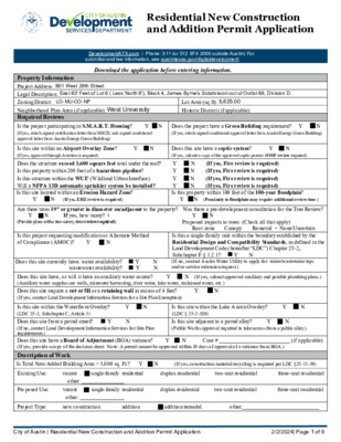
Residential New Construction and Addition Permit Application DevelopmentATX.com | Phone: 311 (or 512 974 2000 outside Austin) For - - submittal and fee information, see austintexas.gov/digitaldevelopment Download the application before entering information. Property Information Project Address: Legal Description: Zoning District: Neighborhood Plan Area (if applicable): Required Reviews Is the project participating in S.M.A.R.T. Housing? (If yes, attach signed certification letter from NHCD, and signed conditional approval letter from Austin Energy Green Building) Y Lot Area (sq ft): Historic District (if applicable): N N Does the project have a Green Building requirement? Y (If yes, attach signed conditional approval letter from Austin Energy Green Building) Is this site within an Airport Overlay Zone? (If yes, approval through Aviation is required) Y N Does this site have a septic system? (If yes, submit a copy of the approved septic permit. OSSF review required) N Y Does the structure exceed 3,600 square feet total under the roof? Is this property within 200 feet of a hazardous pipeline? Is this structure within the WUI? (Wildland Urban Interface) Will a NFPA 13D automatic sprinkler system be installed? Is this site located within an Erosion Hazard Zone? (If yes, EHZ review is required) Y N N N N N Y (If yes, Fire review is required) Y (If yes, Fire review is required) Y (If yes, Fire review is required) Y (If yes, Fire review is required) Is this property within 100 feet of the 100-year floodplain? (Proximity to floodplain may require additional review time.) Y N Are there trees 19” or greater in diameter on/adjacent to the property? Was there a pre-development consultation for the Tree Review? (Provide plans with a tree survey, tree review required) Proposed impacts to trees: (Check all that apply) If yes, how many? N Y Y N Is this project requesting modification or Alternate Method of Compliance (AMOC)? Y N Does this site currently have: water availability? wastewater availability? Y Y N N Does this site have, or will it have an auxiliary water source? (Auxiliary water supplies are wells, rainwater harvesting, river water, lake water, reclaimed water, etc.) Does this site require a cut or fill or a retaining wall in excess of 4 feet? (If yes, contact Land Development Information Services for a Site Plan Exemption) N N Y Y Root zone Removal None/Uncertain Canopy Is this a single-family unit within the boundary established by the Residential Design and Compatibility Standards, as defined in the Land Development Code (hereafter “LDC”) Chapter 25-2, Subchapter F § 1.2.1? Y (If no, contact Austin Water Utility to apply for water/wastewater taps and/or service extension request.) N (If yes, submit approved auxiliary and potable plumbing plans.) Y Is this site within the Waterfront Overlay? (LDC 25-2, Subchapter C, Article 3) Does this site front a paved street? (If no, contact Land Development Information Services for Site Plan requirements.) Does this site have a Board of Adjustment (BOA) variance? (If yes, provide a copy of the decision sheet. Note: A permit cannot be approved within 10 days of approval of a variance from BOA.) Is this site within the Lake Austin Overlay? (LDC § 25-2-180) Is this site adjacent to a paved alley? (Public Works approval required to take access from a public alley.) Case # Y N N N N Y Y N Y (if applicable) Description of Work Is Total New/Added Building Area > 5,000 sq. Ft.? Y N (If yes, construction material recycling is required per LDC §25-11-39) Existing Use: single-family residential duplex residential two-unit residential three-unit residential Proposed Use: single-family residential duplex residential two-unit residential three-unit residential vacant other: vacant other: Project Type: new construction addition addition/remodel other: City of Austin | Residential New Construction and Addition Permit Application 2/2/2024| Page 1 of 9 ' 4 7 5 N 05D00'21" W 48.89' ' 6 7 5 Exist. Conc. Drain 10' Rear Setback AC AC " 4 - ' 0 1 ' 8 7 5 WM ' 9 7 5 = . v e E l New Wood Stair Trash Box New Rear Covered Porch Area of 2nd Floor Addition Existing One Story Frame House k c a etb 5' S 1 C/O Ex. Convered Entry 4' 3.1 6" E 8 3 7 0 D 1 S 6 E et s) arie 9th Stre (R.O.W. V st 2 e W EM Exist. Conc. Drain 25' Building Line Ex. Concrete Porch Building Line Ex. Conc. Walk ' 5 . 8 7 5 = . v e E l 16.75" 3-Trunk Hackberry alk c. W n o C 2 t n e T 1 t n e T " 0 - ' 0 4 ' 4 1 . 3 8 W ' " 0 0 0 3 D 5 8 N ' 3 7 5 = . v e E l t e e r c n o C d n a t n a P i t u o - h s a W k c a b t e S ' 5 ' 4 7 5 = . v e E l l s a i r e t a M e g a r o S t Exist. Conc. Drive Portable Toilet S 05D01'13" W 48.89' E Assumed North E Site Plan 1/8"=1'-0" (1/16" at 11"x17" a. Smoke Alarms: Provide Smoke Alarms - hard wired, interconnected, battery backup, at each sleeping room and immediate common area outside of sleeping rooms. If applicable, on each additional story including basements and habitable attics. In accordance with 2021 IRC Sec R314. b. Carbon Monoxide Alarms: Provide Carbon Monoxide Alarm - hard wired with battery backup, installed outside of each separate sleeping area in the immediate vicinity of the bedrooms in dwelling units within which fuel-fired appliances are installed and/or have an attached garage. In accordance with 2021 IRC sec R315" SHEET INDEX SITE PLAN / DEMOLITION PLAN Not Used FLOOR PLANS TENT DIAGRAMS BUILDING SECTIONS STRUCTURAL NOTES STRUCTURAL NOTES FOUNDATION PLAN MAIN FLOOR FRAMING PLAN 2nd FLOOR FRAMING PLAN ROOF FRAMING PLAN 2nd FLOOR BRACED WALL PLAN FOUNDATION DETAILS FOUNDATION DETAILS FRAMING DETAILS FRAMING DETAILS A-1.0 A-2.0 A-3.0 A-4.0 A-5.0 S0.0 S0.1 S1.0 S2.0 S2.1 S2.2 S2.3 S3.0 S3.1 S4.0 S4.1 " 0 - ' 2 Remove Existing Pair and Save Remove Existing Wood and Concrete Stairs Remove Existing Door Remove Kitchen Cabinets and Fixtures . c e N s a e c a r B Remove Window and Prep for New Door Remove Existing Patio Roof Demolish Bath to Studs Remove Existing Door Remove Clo. Brace as Nec. Remove Closets as Nec. Replace Exist. Dr. Remove Clo. Rough Opening for New Pair Remove Cased Opening Remove Existing Door 28'-1 1/2" PROJECT INFORMATION Address: 801 West 29th Street Austin, Texas 78704 Legal: East 83 Feet of Lot 6 (Less North 6 Feet) Block "4", James Byrne's Subdivision Out of Outlot 69, Division D Vol. 3; Page 72 of the Travis County Deed Records Zoning: LO-MU-CO-NP LEGEND Property Line Fencing Setback Public Util. Easement Electrical Service New Addition Existing Structure E Power Pole Fire Hydrant Water Meter Sewer Cleanout PP FH WM C/O Wall to Remain Wall to Remove Demolition Plan 1/4"=1'-0" (1/8"=1'-0" at 11"x17") Remove and Reframe For New Dormer 12 12 Entry Exist. Asphalt Roofing Remove and Reframe For New Dormer 24'-3" 12 10 Remove Window Entry Remove Wall as Needed for New Window Remove Exist. Roof Remove Exist. Shed Roof Remove Exist. Wood Stair Remove This Exiting Roof Area Exist. Roof to Remain Remove Windows Remove Shed Roof Remove Door Remove Exist. Wood Stair Existing North Elevation 1/8"=1'-0" (1/16" at 11"x17" Existing East Elevation 1/8"=1'-0" (1/16" at 11"x17" Existing South Elevation 1/8"=1'-0" (1/16" at 11"x17" Existing West Elevation 1/8"=1'-0" (1/16" at 11"x17" Remove and Reframe For New Dormer Remove Exist. Roofs Remove Gable Wall as Necessary For New Extended Gable and Bay 12 10 Remove Exist. Stair N G I S E D / R E M M A H p i h s r e n t r a p n o i t c u r t s n o c & e r u t c e t i h c r a l a i t n e d i s e r A s a x e T , n i t s u A t e e r t S h t 5 . S 8 0 2 3 2 6 6 2 - 6 2 6 - 2 1 5 : t c a t n o C Seal t c e j o r P t e e r t S h t 9 2 t s e W s a x e T , n i t s u A t e e r t S h t 9 2 t s e W 1 0 8 Date: 10/02/23 Site Plan/ Demolition Plan/ Exist. Elevs. Revised: 03/11/24 Revised: 00/00/00 Revised: 00/00/00 A-1 These Drawings are the property of the Architect and may only be used in connection with this project. ' 4 7 5 N 05D00'21" W 48.89' ' 6 7 5 Exist. Conc. Drain 10' Rear Setback AC AC New Wood Stair Trash Box New Rear Covered Porch Area of 2nd Floor Addition Existing One Story Frame House EM Exist. Conc. Drain 25' Building Line 2 t n e T 1 t n e T " 0 - ' 0 4 ' 4 1 . 3 8 W ' " 0 0 0 3 D 5 8 N ' 3 7 5 = . v e E l t e e r c n o C d n a t n a P i t u o - h s a W k c a b t e S ' 5 ' 4 7 5 = . v e E l l s a i r e t a M e g a r o S t " 4 - ' 0 1 ' 8 7 5 ' 9 7 5 = . v e E l 4' 3.1 6" E 8 3 7 0 D 1 S 6 E et s) arie 9th Stre (R.O.W. V st 2 e W k c a etb 5' S 1 Ex. Convered Entry Ex. Concrete Porch Building Line 36" 3-Trunk Hackberry Ex. Conc. Walk ' 5 . 8 7 5 = . v e E l alk c. W n o C E Exist. Conc. Drive Portable Toilet S 05D01'13" W 48.89' Assumed North E Site Plan 1/8"=1'-0" (1/16" at 11"x17" a. Smoke Alarms: Provide Smoke Alarms - hard wired, interconnected, battery backup, at each sleeping room and immediate common area outside of sleeping rooms. If applicable, on each additional story including basements and habitable attics. In accordance with 2021 IRC Sec R314. b. Carbon Monoxide Alarms: Provide Carbon Monoxide Alarm - hard wired with battery backup, installed outside of each separate sleeping area in the immediate vicinity of the bedrooms in dwelling units within which fuel-fired appliances are installed and/or have an attached garage. In accordance with 2021 IRC sec R315" SHEET INDEX SITE PLAN / DEMOLITION PLAN Not Used FLOOR PLANS TENT DIAGRAMS BUILDING SECTIONS STRUCTURAL NOTES STRUCTURAL NOTES FOUNDATION PLAN MAIN FLOOR FRAMING PLAN 2nd FLOOR FRAMING PLAN ROOF FRAMING PLAN 2nd FLOOR BRACED WALL PLAN FOUNDATION DETAILS FOUNDATION DETAILS FRAMING DETAILS FRAMING DETAILS A-1.0 A-2.0 A-3.0 A-4.0 A-5.0 S0.0 S0.1 S1.0 S2.0 S2.1 S2.2 S2.3 S3.0 S3.1 S4.0 S4.1 " 0 - ' 2 Remove Existing Pair and Save Remove Existing Wood and Concrete Stairs Remove Existing Door Remove Kitchen Cabinets and Fixtures . c e N s a e c a r B Remove Window and Prep for New Door Remove Existing Patio Roof Demolish Bath to Studs Remove Existing Door Remove Clo. Brace as Nec. Remove Closets as Nec. Replace Exist. Dr. Remove Clo. Rough Opening for New Pair Remove Cased Opening Remove Existing Door 28'-1 1/2" PROJECT INFORMATION Address: 801 West 29th Street Austin, Texas 78704 Legal: East 83 Feet of Lot 6 (Less North 6 Feet) Block "4", James Byrne's Subdivision Out of Outlot 69, Division D Vol. 3; Page 72 of the Travis County Deed Records Zoning: LO-MU-CO-NP LEGEND Property Line Fencing Setback Public Util. Easement Electrical Service New Addition Existing Structure Power Pole Fire Hydrant PP FH E Wall to Remain Wall to Remove Demolition Plan 1/4"=1'-0" (1/8"=1'-0" at 11"x17") Remove and Reframe For New Dormer 12 12 Entry Exist. Asphalt Roofing Remove and Reframe For New Dormer 24'-3" 12 10 Remove Window Entry Remove Wall as Needed for New Window Remove Exist. Roof Remove Exist. Shed Roof Remove Exist. Wood Stair Remove This Exiting Roof Area Exist. Roof to Remain Remove Windows Remove Shed Roof Remove Door Remove Exist. Wood Stair Existing North Elevation 1/8"=1'-0" (1/16" at 11"x17" Existing East Elevation 1/8"=1'-0" (1/16" at 11"x17" Existing South Elevation 1/8"=1'-0" (1/16" at 11"x17" Existing West Elevation 1/8"=1'-0" (1/16" at 11"x17" Remove and Reframe For New Dormer Remove Exist. Roofs Remove Gable Wall as Necessary For New Extended Gable and Bay 12 10 Remove Exist. Stair N G I S E D / R E M M A H p i h s r e n t r a p n o i t c u r t s n o c & e r u t c e t i h c r a l a i t n e d i s e r A s a x e T , n i t s u A t e e r t S h t 5 . S 8 0 2 3 2 6 6 2 - 6 2 6 - 2 1 5 : t c a t n o C Seal t c e j o r P t e e r t S h t 9 2 t s e W s a x e T , n i t s u A t e e r t S h t 9 2 t s e W 1 0 8 Date: 10/02/23 Site Plan/ Demolition Plan/ Exist. Elevs. Revised: 00/00/23 Revised: 00/00/00 Revised: 00/00/00 A-1 These Drawings are the property of the Architect and may only be used in connection with this project. Dining Attic Existing Wall Remove Existing Stair Infill Exist. Door D D DW A- A5 New Wall A- A5 10'-4" New Bar Peninsula Remodeled Kitchen Dining Relocate Doors " 3 - ' 0 1 0 5' New Dormers Above Living " 3 - ' 6 1 New Window " 8 3 / 3 - ' 1 1 Drive Below B- A5 B- A5 Mid-Landing Mud Room UP Top Landing New Covered Deck Attic Ladder New Door Ref. Pantry 6'-5 1/2" Living Bath 2 Replace Exist. Dr. w/ 30" Swing " 1 - ' 5 Infill Exist. Door New Pair- to match " 0 1 Bath 1 2'-9" Ex. Door to Remain Ex. Door to Remain Infill Exist. Door " 4 - ' 2 Landing 3'-1 1/2" Wall to Underside of Stair New 30" Swing Dr. 6'-5" Infill Exist. Window. New Closet New 30" Swing Dr. Infill Exist. Door Area to be Furred Down to 8' Ceiling New 30" Door 4'-9" . . a e " 5 7 @ R 6 1 l r o o F d n 2 o t p U i n a m e R o T s w o d n W i . x E 1st Level Floor Plan 1/4"=1'-0" Assumed North C- A5 C- A5 2nd Level Floor Plan 1/4"=1'-0" Assumed North Bedroom 1 Bedroom 2 Ex. Windows To Remain Ex. Windows To Remain " 8 - ' 6 1 " 3 - ' 4 2 " 3 - ' 1 1 " 2 1 / 2 - ' 4 15'-0" Bedroom 3 i w o d n W m o o r d e B h g H i S S E R G E - New Shed Dormer Above Attic Attic Ladder Closet Kitchen Bath 3 High Stair Window 10" Down 16R @ 7.5" ea. 10' Attic " 5 - ' 1 1 Bedroom 4 Bath 4 HVAC Attic 5' Closet Closet 1st Level Air Handler Service Access 5' New Shed Dormer Above New Bedroom Window 12'-3 3/4" Exist. 10:12 Slope New Shed Dormer 2:12 New 10:12 Slope i e g d R w e N d e s o p o r P d e d n e t x E e b o t i e g d R g n i t s x E i New Dormer Existing Chimney New Dormer l e p o S 2 1 2 1 . t s x E : i l e p o S 2 1 : 2 1 . t s x E i A- A5 5'-10" 9" " 2 - ' 3 Up No Access Exist. 2x10" YP Ceiling Joists @ 20" O.C. - Sistered Over 4x6" Beams To Remain in Place- See Structural for Additional Blocking and Beam Requirements. Replace Existing Cedar Posts with 4"x6" Treated Posts on New 30"x30" Footings- (See Structural). Chimney Foundation Exist. 10:12 Slope Exist. Crawlspace Entry 10'-1" 4'-8" 5'-10" 6'-2" 7'-11" 6'-11" 5'-1" Exist. 10:12 Slope New Shed Dormer 2:12 Proposed Roof Plan 1/4"=1'-0" Assumed North 17"x17" Brick Flue Legend New Treated Post Perimeter Concrete Walls (Hgt. Varies) Exposed 2x4" Framed Wall w/ 4x6" Beam (Cont.) Exposed 2x4" Framed Wall (No Beam) 2x4" Framed Wall w/ Shiplap One Side Crawspace Floor Plan 1/4"=1'-0" Assumed North " 1 - ' 7 " 1 1 - ' 2 " 0 - ' 8 Footer/Landing n g i l A New 18"x18" Footers w/ 4"x4" Treated Posts on Simpson anchors. (See Structural) B- A5 C- A5 " 7 - ' 1 1 " 2 / 1 4 - ' 1 1 " 2 / 1 3 - ' 2 1 N G I S E D / R E M M A H p i h s r e n t r a p n o i t c u r t s n o c & e r u t c e t i h c r a l a i t n e d i s e r A s a x e T , n i t s u A t e e r t S h t 5 . S 8 0 2 3 2 6 6 2 - 6 2 6 - 2 1 5 : t c a t n o C Seal t c e j o r P t e e r t S h t 9 2 t s e W s a x e T , n i t s u A t e e r t S h t 9 2 t s e W 1 0 8 Date: 10/01/23 Floor Plan Revised: 02/12/24 Revised: 00/00/00 Revised: 00/00/00 A-3 These Drawings are the property of the Architect and may only be used in connection with this project. Dining Attic Existing Wall Remove Existing Stair Infill Exist. Door D D DW A- A5 New Wall A- A5 10'-4" New Bar Peninsula Remodeled Kitchen Dining Relocate Doors " 3 - ' 0 1 0 5' New Dormers Above Living " 3 - ' 6 1 New Window " 8 3 / 3 - ' 1 1 Drive Below B- A5 B- A5 Mid-Landing Mud Room UP Top Landing New Covered Deck Attic Ladder New Door Ref. Pantry 6'-5 1/2" Living Bath 2 Replace Exist. Dr. w/ 30" Swing " 1 - ' 5 Infill Exist. Door New Pair- to match " 0 1 Bath 1 2'-9" Ex. Door to Remain Ex. Door to Remain Infill Exist. Door " 4 - ' 2 Landing 3'-1 1/2" Wall to Underside of Stair New 30" Swing Dr. 6'-5" Infill Exist. Window. New Closet New 30" Swing Dr. Infill Exist. Door Area to be Furred Down to 8' Ceiling New 30" Door 4'-9" . . a e " 5 7 @ R 6 1 l r o o F d n 2 o t p U i n a m e R o T s w o d n W i . x E 1st Level Floor Plan 1/4"=1'-0" Assumed North C- A5 C- A5 2nd Level Floor Plan 1/4"=1'-0" Assumed North Bedroom 1 Bedroom 2 Ex. Windows To Remain Ex. Windows To Remain " 8 - ' 6 1 " 3 - ' 4 2 " 3 - ' 1 1 " 2 1 / 2 - ' 4 15'-0" Bedroom 3 i w o d n W m o o r d e B h g H i S S E R G E - New Shed Dormer Above Attic Attic Ladder Closet Kitchen Bath 3 High Stair Window 10" Down 16R @ 7.5" ea. 10' Attic " 5 - ' 1 1 Bedroom 4 Bath 4 HVAC Attic 5' Closet Closet 1st Level Air Handler Service Access 5' New Shed Dormer Above New Bedroom Window 12'-3 3/4" Exist. 10:12 Slope New Shed Dormer 2:12 New 10:12 Slope i e g d R w e N d e s o p o r P d e d n e t x E e b o t i e g d R g n i t s x E i New Dormer Existing Chimney New Dormer l e p o S 2 1 2 1 . t s x E : i l e p o S 2 1 : 2 1 . t s x E i A- A5 5'-10" 9" " 2 - ' 3 Up No Access Exist. 2x10" YP Ceiling Joists @ 20" O.C. - Sistered Over 4x6" Beams To Remain in Place- See Structural for Additional Blocking and Beam Requirements. Replace Existing Cedar Posts with 4"x6" Treated Posts on New 30"x30" Footings- (See Structural). Chimney Foundation Exist. 10:12 Slope Exist. Crawlspace Entry 10'-1" 4'-8" 5'-10" 6'-2" 7'-11" 6'-11" 5'-1" Exist. 10:12 Slope New Shed Dormer 2:12 Proposed Roof Plan 1/4"=1'-0" Assumed North 17"x17" Brick Flue Legend New Treated Post Perimeter Concrete Walls (Hgt. Varies) Exposed 2x4" Framed Wall w/ 4x6" Beam (Cont.) Exposed 2x4" Framed Wall (No Beam) 2x4" Framed Wall w/ Shiplap One Side Crawspace Floor Plan 1/4"=1'-0" Assumed North " 1 - ' 7 " 1 1 - ' 2 " 0 - ' 8 Footer/Landing n g i l A New 18"x18" Footers w/ 4"x4" Treated Posts on Simpson anchors. (See Structural) B- A5 C- A5 " 7 - ' 1 1 " 2 / 1 4 - ' 1 1 " 2 / 1 3 - ' 2 1 N G I S E D / R E M M A H p i h s r e n t r a p n o i t c u r t s n o c & e r u t c e t i h c r a l a i t n e d i s e r A s a x e T , n i t s u A t e e r t S h t 5 . S 8 0 2 3 2 6 6 2 - 6 2 6 - 2 1 5 : t c a t n o C Seal t c e j o r P t e e r t S h t 9 2 t s e W s a x e T , n i t s u A t e e r t S h t 9 2 t s e W 1 0 8 Date: 10/01/23 Floor Plan Revised: 02/12/24 Revised: 00/00/00 Revised: 00/00/00 A-3 These Drawings are the property of the Architect and may only be used in connection with this project. Max. Height Area of Gable Penetration into Side Yard Setback Plane- Ref. 2.6-E-4b of Subchapter F 9'-10" Attic New Roofline New Dormer Proposed Flat Ceiling High Bedroom Window -Egress i e n L y t r e p o r P Existing Roof New 2nd Floor Level 1'-4" Existing Floor Level 45 Deg. i e n L y t r e p o r P High Elev. = 579' Seal New Wood Stair w/ Railing to Code Median Elev. = 576' 7'-2 7/8" Tent 1 40'-0" Proposed West Elevation 1/8"=1'-0" (1/4"=1'-0" at 11"x17") Low Elev. = 573' Area of Gable Penetration into Side Yard Setback Plane- Ref. 2.6-E-4b of Subchapter F 32' Max. Height New Roof Proposed Flat Ceiling EGRESS EGRESS 1'-0" Existing Roof 'Teardrop' Siding to Match " 0 - ' 5 1 i e n L y t r e p o r P High Elev. = 579' Exist F.F. = 579.2' Remove Door New Covered Porch Median Elev.= 576' Low Elev. = 573' New Stair w/ Railing to Code Crawlspace Beyond New 6x6" Wood Post and Pier- (See Struct.) Springline 2nd Level Roof E " 0 - ' 2 3 Proposed Attic Floor Clg. " 0 - ' 9 i e n L g n d i l i u B Deck Piers- (See Struct.) Proposed South Elevation 1/8"=1'-0" (1/16"=1'-0" at 11"x17") i e n L y t r e p o r P N G I S E D / R E M M A H p i h s r e n t r a p n o i t c u r t s n o c & e r u t c e t i h c r a l a i t n e d i s e r A s a x e T , n i t s u A t e e r t S h t 5 . S 8 0 2 3 2 6 6 2 - 6 2 6 - 2 1 5 : t c a t n o C t c e j o r P t e e r t S h t 9 2 t s e W s a x e T , n i t s u A t e e r t S h t 9 2 t s e W 1 0 8 Date: 10/01/23 Tent Diagrams Revised: 02/12/24 Revised: 00/00/00 Revised: 00/00/00 A-4.1 These Drawings are the property of the Architect and may only be used in connection with this project. New Ridge 12 10 Field Verify Existing Slope & Match New Attic Dormer Beam-See Struct. 12 2 Proposed Clg. Hgt. 11" ? Egress Bed 3 Dining Existing Eave 2"x8" sistered to existing rafters 2"x8" sistered to existing rafters Living 2"x10" sistered to existing ceiling joists " 0 1 Kitchen Mud Rm. Dining Living Living " 3 - ' 9 Plate Beyond " 0 - ' 9 " 0 - ' 6 2nd Floor Exist. Ceiling Extend Exist. Wall Plate to Match 1st Fl. Plate Exist 1st Floor New 1-3/4" x 11-1/4" LVL Ridge-See Struct. 2x10"s @ 24" o.c. 12 10 Field Verify Existing Slope & Match 2x4" Jacks as Nec. New Attic Existing Ridge w/ (2) LVLs Sistered- See Struct. Existing Chimney 2nd Level Air Handler ? 20x20" Fixed @ East Stair Wall ? Beam E xist. R o of to b e R e m o v e d Kitchen Beyond Bath 4 " 8 - ' 5 Vanity 2"x8" sistered to existing rafters Duct Chase Living Beyond Proposed Ceiling Plate Line " 0 - ' 8 " 0 - ' 6 2nd Floor Level Attic Ladder Exist. Wall Plate 1-3/4" x 9-1/4"LVL sistered to existing ceiling joists Duct Chase Furr-down Ceiling w/ 2x4's - Flat Framed " 3 - ' 9 New Covered Porch Rear Entry 16 Risers @7.5" each Passsage to Dining Main Hallway To Living Entry Stairwell 14" LVL Stair Stringer Remodeled Hall Bath 1 Vanity Fully Enclosed Area Existing Crawlspace 40'-3" Field Verify Building Section- A 1/4"=1'-0" Crawlspace Access Replace Exist. Cedar Posts w/ New 4x6" Treated w/ Simpson Post Anchor on New 30x30"x18" Deep Footers- See Struct. Replace Exist. 4x6" Beam w/ (2) 1-7/8" x 9-1/2" LVLs. Existing Crawlspace Exist. Conc. Retaining Wall Exist. 1st Level New Wood Stair w/ Railing to Code Seal 1/4"=1'-0" Building Section- B New Roofline 12 10 New Ceiling Hgt. New Plate Hgt. Beyond " 0 - ' 8 " 0 - ' 6 Stair Ceiling High Stair Window ? Attic New Attic Beyond Existing Chimney Existing Ridge to Remain. 12 2 New Shed Dormer ? New 2x6" Rafters Stair Landing Beyond Typ. Headers- See Struct. New Dormer ? Living Area Beyond New Roofing Air Handler New @nd Level Sub-floor Bedroom 4 Closet Mech. Attic 2"x10" sistered to existing ceiling joists- See Struct. for Additional Blocking and Beams Bedroom 1 Bedroom 2 New Entry Door Closet Beyond Bath 1 Beyond Hall Beyond Hall Beyond Closet Beyond Exist. Entry New Covered Porch " 3 - ' 9 New Wood Stair Exist. 2x10" Joists @ 20"o.c.- See Structural for Additional Beams/ Blocking Req'd Replace Exist. Cedar Posts w/ New 4x6" Treated w/ Simpson Post Anchor on New 30x30"x18" Deep Footers- See Struct. Replace Exist. 4x6" Beam w/ (2) 1-7/8" x 9-1/2" LVLs. Existing Crawlspace Exist. Conc. Retaining Wall 28'-1 1/2" F.V. Building Section- C 1/4"=1'-0" N G I S E D / R E M M A H p i h s r e n t r a p n o i t c u r t s n o c & e r u t c e t i h c r a l a i t n e d i s e r A s a x e T , n i t s u A t e e r t S h t 5 . S 8 0 2 3 2 6 6 2 - 6 2 6 - 2 1 5 : t c a t n o C t c e j o r P t e e r t S h t 9 2 t s e W s a x e T , n i t s u A t e e r t S h t 9 2 t s e W 1 0 8 Date: 10/01/23 Building Sections Revised: 02/12/24 Revised: 00/00/00 Revised: 00/00/00 A-5 These Drawings are the property of the Architect and may only be used in connection with this project. Max. Height Area of Gable Penetration into Side Yard Setback Plane- Ref. 2.6-E-4b of Subchapter F 9'-10" Attic New Roofline New Dormer Proposed Flat Ceiling High Bedroom Window -Egress i e n L y t r e p o r P Existing Roof New 2nd Floor Level 1'-4" Existing Floor Level 45 Deg. i e n L y t r e p o r P High Elev. = 579' Seal New Wood Stair w/ Railing to Code Median Elev. = 576' 7'-2 7/8" Tent 1 40'-0" Proposed West Elevation 1/8"=1'-0" (1/4"=1'-0" at 11"x17") Low Elev. = 573' Area of Gable Penetration into Side Yard Setback Plane- Ref. 2.6-E-4b of Subchapter F 32' Max. Height New Roof Proposed Flat Ceiling EGRESS EGRESS 1'-0" Existing Roof 'Teardrop' Siding to Match " 0 - ' 5 1 i e n L y t r e p o r P High Elev. = 579' Exist F.F. = 579.2' Remove Door New Covered Porch Median Elev.= 576' Low Elev. = 573' New Stair w/ Railing to Code Crawlspace Beyond New 6x6" Wood Post and Pier- (See Struct.) Springline 2nd Level Roof E " 0 - ' 2 3 Proposed Attic Floor Clg. " 0 - ' 9 i e n L g n d i l i u B Deck Piers- (See Struct.) Proposed South Elevation 1/8"=1'-0" (1/16"=1'-0" at 11"x17") i e n L y t r e p o r P N G I S E D / R E M M A H p i h s r e n t r a p n o i t c u r t s n o c & e r u t c e t i h c r a l a i t n e d i s e r A s a x e T , n i t s u A t e e r t S h t 5 . S 8 0 2 3 2 6 6 2 - 6 2 6 - 2 1 5 : t c a t n o C t c e j o r P t e e r t S h t 9 2 t s e W s a x e T , n i t s u A t e e r t S h t 9 2 t s e W 1 0 8 Date: 10/01/23 Tent Diagrams Revised: 02/12/24 Revised: 00/00/00 Revised: 00/00/00 A-4.1 These Drawings are the property of the Architect and may only be used in connection with this project. Proposed North Elevation 1/8"=1'-0" (1/16"=1'-0" at 11"x17") " 0 - ' 2 3 " 8 / 1 9 - ' 9 2 48" x 20"H Slider i e n L g n d i l i u B i e n L y t r e p o r P 40'-0" Tent 1 7'-2 7/8" Tent 2 32' Max. Height Extended Portion of Existing Roof New Dormers Existing Roof New Casement Window- 16" x 32"H Area of Gable Penetration into Side Yard Setback Plane- Ref. 2.6-E-4b of Subchapter F 45 Deg. i e n L y t r e p o r P Exist F.F. = 579.2' High Elev. = 579' Median Elev.= 576' Low Elev. = 573' Entry Exist. Masonry Chimney " 0 - ' 5 1 Seal Proposed Flat Ceiling New Roofline " 8 1 / 9 - ' 9 2 " 0 - ' 5 1 i e n L y t r e p o r P " 0 - ' 6 " 3 - ' 9 New Wood Stair 9'-10" 32' Max. Height Area of Gable Penetration into Side Yard Setback Plane- Ref. 2.6-E-4b of Subchapter F Stair Ceiling High Stair Window New Dormer 36" x 60" Sing. HUng EGRESS Exist. Chimney New Dormer Existing Roof 45 Deg. New Entry Door Existing House Entry i e n L y t r e p o r P Exist F.F. = 579.2' Existing Crawlspace Proposed East Elevation 1/8"=1'-0" (1/16"=1'-0" at 11"x17") " 0 - ' 5 1 High Elev. = 579'' Median Elev.= 576' Low Elev. = 573' N G I S E D / R E M M A H p i h s r e n t r a p n o i t c u r t s n o c & e r u t c e t i h c r a l a i t n e d i s e r A s a x e T , n i t s u A t e e r t S h t 5 . S 8 0 2 3 2 6 6 2 - 6 2 6 - 2 1 5 : t c a t n o C t c e j o r P t e e r t S h t 9 2 t s e W s a x e T , n i t s u A t e e r t S h t 9 2 t s e W 1 0 8 Date: 10/01/23 Tent Diagrams Revised: 02/12/24 Revised: 00/00/00 Revised: 00/00/00 A-4.0 These Drawings are the property of the Architect and may only be used in connection with this project. New Ridge 12 10 Field Verify Existing Slope & Match New Attic Dormer Beam-See Struct. 12 2 Proposed Clg. Hgt. 11" ? Egress Bed 3 Dining Existing Eave 2"x8" sistered to existing rafters 2"x8" sistered to existing rafters Living 2"x10" sistered to existing ceiling joists " 0 1 Kitchen Mud Rm. Dining Living Living " 3 - ' 9 Plate Beyond " 0 - ' 9 " 0 - ' 6 2nd Floor Exist. Ceiling Extend Exist. Wall Plate to Match 1st Fl. Plate Exist 1st Floor New 1-3/4" x 11-1/4" LVL Ridge-See Struct. 2x10"s @ 24" o.c. 12 10 Field Verify Existing Slope & Match 2x4" Jacks as Nec. New Attic Existing Ridge w/ (2) LVLs Sistered- See Struct. Existing Chimney 2nd Level Air Handler ? 20x20" Fixed @ East Stair Wall ? Beam E xist. R o of to b e R e m o v e d Kitchen Beyond Bath 4 " 8 - ' 5 Vanity 2"x8" sistered to existing rafters Duct Chase Living Beyond Proposed Ceiling Plate Line " 0 - ' 8 " 0 - ' 6 2nd Floor Level Attic Ladder Exist. Wall Plate 1-3/4" x 9-1/4"LVL sistered to existing ceiling joists Duct Chase Furr-down Ceiling w/ 2x4's - Flat Framed " 3 - ' 9 New Covered Porch Rear Entry 16 Risers @7.5" each Passsage to Dining Main Hallway To Living Entry Stairwell 14" LVL Stair Stringer Remodeled Hall Bath 1 Vanity Fully Enclosed Area Existing Crawlspace 40'-3" Field Verify Building Section- A 1/4"=1'-0" Crawlspace Access Replace Exist. Cedar Posts w/ New 4x6" Treated w/ Simpson Post Anchor on New 30x30"x18" Deep Footers- See Struct. Replace Exist. 4x6" Beam w/ (2) 1-7/8" x 9-1/2" LVLs. Existing Crawlspace Exist. Conc. Retaining Wall Exist. 1st Level New Wood Stair w/ Railing to Code Seal 1/4"=1'-0" Building Section- B New Roofline 12 10 New Ceiling Hgt. New Plate Hgt. Beyond " 0 - ' 8 " 0 - ' 6 Stair Ceiling High Stair Window ? Attic New Attic Beyond Existing Chimney Existing Ridge to Remain. 12 2 New Shed Dormer ? New 2x6" Rafters Stair Landing Beyond Typ. Headers- See Struct. New Dormer ? Living Area Beyond New Roofing Air Handler New @nd Level Sub-floor Bedroom 4 Closet Mech. Attic 2"x10" sistered to existing ceiling joists- See Struct. for Additional Blocking and Beams Bedroom 1 Bedroom 2 New Entry Door Closet Beyond Bath 1 Beyond Hall Beyond Hall Beyond Closet Beyond Exist. Entry New Covered Porch " 3 - ' 9 New Wood Stair Exist. 2x10" Joists @ 20"o.c.- See Structural for Additional Beams/ Blocking Req'd Replace Exist. Cedar Posts w/ New 4x6" Treated w/ Simpson Post Anchor on New 30x30"x18" Deep Footers- See Struct. Replace Exist. 4x6" Beam w/ (2) 1-7/8" x 9-1/2" LVLs. Existing Crawlspace Exist. Conc. Retaining Wall 28'-1 1/2" F.V. Building Section- C 1/4"=1'-0" N G I S E D / R E M M A H p i h s r e n t r a p n o i t c u r t s n o c & e r u t c e t i h c r a l a i t n e d i s e r A s a x e T , n i t s u A t e e r t S h t 5 . S 8 0 2 3 2 6 6 2 - 6 2 6 - 2 1 5 : t c a t n o C t c e j o r P t e e r t S h t 9 2 t s e W s a x e T , n i t s u A t e e r t S h t 9 2 t s e W 1 0 8 Date: 10/01/23 Building Sections Revised: 02/12/24 Revised: 00/00/00 Revised: 00/00/00 A-5 These Drawings are the property of the Architect and may only be used in connection with this project. Proposed North Elevation 1/8"=1'-0" (1/16"=1'-0" at 11"x17") " 0 - ' 2 3 " 8 / 1 9 - ' 9 2 48" x 20"H Slider i e n L g n d i l i u B i e n L y t r e p o r P 40'-0" Tent 1 7'-2 7/8" Tent 2 32' Max. Height Extended Portion of Existing Roof New Dormers Existing Roof New Casement Window- 16" x 32"H Area of Gable Penetration into Side Yard Setback Plane- Ref. 2.6-E-4b of Subchapter F 45 Deg. i e n L y t r e p o r P Exist F.F. = 579.2' High Elev. = 579' Median Elev.= 576' Low Elev. = 573' Entry Exist. Masonry Chimney " 0 - ' 5 1 Seal Proposed Flat Ceiling New Roofline " 8 1 / 9 - ' 9 2 " 0 - ' 5 1 i e n L y t r e p o r P " 0 - ' 6 " 3 - ' 9 New Wood Stair 9'-10" 32' Max. Height Area of Gable Penetration into Side Yard Setback Plane- Ref. 2.6-E-4b of Subchapter F Stair Ceiling High Stair Window New Dormer 36" x 60" Sing. HUng EGRESS Exist. Chimney New Dormer Existing Roof 45 Deg. New Entry Door Existing House Entry i e n L y t r e p o r P Exist F.F. = 579.2' Existing Crawlspace Proposed East Elevation 1/8"=1'-0" (1/16"=1'-0" at 11"x17") " 0 - ' 5 1 High Elev. = 579'' Median Elev.= 576' Low Elev. = 573' N G I S E D / R E M M A H p i h s r e n t r a p n o i t c u r t s n o c & e r u t c e t i h c r a l a i t n e d i s e r A s a x e T , n i t s u A t e e r t S h t 5 . S 8 0 2 3 2 6 6 2 - 6 2 6 - 2 1 5 : t c a t n o C t c e j o r P t e e r t S h t 9 2 t s e W s a x e T , n i t s u A t e e r t S h t 9 2 t s e W 1 0 8 Date: 10/01/23 Tent Diagrams Revised: 02/12/24 Revised: 00/00/00 Revised: 00/00/00 A-4.0 These Drawings are the property of the Architect and may only be used in connection with this project. Dining Attic Existing Wall Remove Existing Stair Infill Exist. Door D D DW A- A5 New Wall A- A5 10'-4" New Bar Peninsula Remodeled Kitchen Dining Relocate Doors " 3 - ' 0 1 0 5' New Dormers Above Living " 3 - ' 6 1 New Window " 8 3 / 3 - ' 1 1 Drive Below B- A5 B- A5 Mid-Landing Mud Room UP Top Landing New Covered Deck Attic Ladder New Door Ref. Pantry 6'-5 1/2" Living Bath 2 Replace Exist. Dr. w/ 30" Swing " 1 - ' 5 Infill Exist. Door New Pair- to match " 0 1 Bath 1 2'-9" Ex. Door to Remain Ex. Door to Remain Infill Exist. Door " 4 - ' 2 Landing 3'-1 1/2" Wall to Underside of Stair New 30" Swing Dr. 6'-5" Infill Exist. Window. New Closet New 30" Swing Dr. Infill Exist. Door Area to be Furred Down to 8' Ceiling New 30" Door 4'-9" . . a e " 5 7 @ R 6 1 l r o o F d n 2 o t p U i n a m e R o T s w o d n W i . x E 1st Level Floor Plan 1/4"=1'-0" Assumed North C- A5 C- A5 2nd Level Floor Plan 1/4"=1'-0" Assumed North Bedroom 1 Bedroom 2 Ex. Windows To Remain Ex. Windows To Remain " 8 - ' 6 1 " 3 - ' 4 2 " 3 - ' 1 1 " 2 1 / 2 - ' 4 15'-0" Bedroom 3 i w o d n W m o o r d e B h g H i S S E R G E - New Shed Dormer Above Attic Attic Ladder Closet Kitchen Bath 3 High Stair Window 10" Down 16R @ 7.5" ea. 10' Attic " 5 - ' 1 1 Bedroom 4 Bath 4 HVAC Attic 5' Closet Closet 1st Level Air Handler Service Access 5' New Shed Dormer Above New Bedroom Window 12'-3 3/4" Exist. 10:12 Slope New Shed Dormer 2:12 New 10:12 Slope i e g d R w e N d e s o p o r P d e d n e t x E e b o t i e g d R g n i t s x E i New Dormer Existing Chimney New Dormer l e p o S 2 1 2 1 . t s x E : i l e p o S 2 1 : 2 1 . t s x E i A- A5 5'-10" 9" " 2 - ' 3 Up No Access Exist. 2x10" YP Ceiling Joists @ 20" O.C. - Sistered Over 4x6" Beams To Remain in Place- See Structural for Additional Blocking and Beam Requirements. Replace Existing Cedar Posts with 4"x6" Treated Posts on New 30"x30" Footings- (See Structural). Chimney Foundation Exist. 10:12 Slope Exist. Crawlspace Entry 10'-1" 4'-8" 5'-10" 6'-2" 7'-11" 6'-11" 5'-1" Exist. 10:12 Slope New Shed Dormer 2:12 Proposed Roof Plan 1/4"=1'-0" Assumed North 17"x17" Brick Flue Legend New Treated Post Perimeter Concrete Walls (Hgt. Varies) Exposed 2x4" Framed Wall w/ 4x6" Beam (Cont.) Exposed 2x4" Framed Wall (No Beam) 2x4" Framed Wall w/ Shiplap One Side Crawspace Floor Plan 1/4"=1'-0" Assumed North " 1 - ' 7 " 1 1 - ' 2 " 0 - ' 8 Footer/Landing n g i l A New 18"x18" Footers w/ 4"x4" Treated Posts on Simpson anchors. (See Structural) B- A5 C- A5 " 7 - ' 1 1 " 2 / 1 4 - ' 1 1 " 2 / 1 3 - ' 2 1 N G I S E D / R E M M A H p i h s r e n t r a p n o i t c u r t s n o c & e r u t c e t i h c r a l a i t n e d i s e r A s a x e T , n i t s u A t e e r t S h t 5 . S 8 0 2 3 2 6 6 2 - 6 2 6 - 2 1 5 : t c a t n o C Seal t c e j o r P t e e r t S h t 9 2 t s e W s a x e T , n i t s u A t e e r t S h t 9 2 t s e W 1 0 8 Date: 10/01/23 Floor Plan Revised: 02/12/24 Revised: 00/00/00 Revised: 00/00/00 A-3 These Drawings are the property of the Architect and may only be used in connection with this project. Water/Wastewater Service Plan Verification Form (WWWSPV) 6310 Wilhelmina Delco Drive | 512-972-1000 Option 3 | AWTaps@austintexas.gov Service Address: Lot: ALL FIELDS ARE REQUIRED Block: Subdivision: Will the dwelling units be demolished? Are there multiple dwelling units on the lot? Land Status or re-subdivision? Original Address: Are new dwelling units being built? Is this a corner lot? Existing Lot Use: Proposed Use: If SFR, sq ft: If Proposed Use is Other, describe the structure to be built: Existing Bath Count: Additional Bath Count: Proposed Bath Count Meter #1: Meter #2: Existing protected trees to remain on lot? Refer to the City Arborist website for required levels of tree protection. Water meters and wastewater cleanouts are not permitted in sidewalks or driveways Relocation of services from sidewalks or driveways shall be performed at the applicant's expense. The applicant listed below attests that the information provided is deemed accurate and complete based on available records. The applicant is responsible to confirm the location and suitability of existing water and wastewater services. The applicant may be responsible for costs associated to corrections due to incomplete or invalid information provided. Applicant Name Date Applicant Phone Applicant Email Submit this form along with plot plan, site plan or building plan to AWTaps@austintexas.gov. Plans must clearly mark all utilities and any tree critical root zones. Failure to comply may result in this form being rejected. Austin Water Use Only - Submit supporting documentation to Applicant when responding Water main size: 6" CI Water service size: 3/4" Water service material: COPPER Existing water service line/meter location: 20' L/RLL Existing Meter #s: 10080353 Existing meter size(s): 5/8" Shared service? NO If Yes, meter #/size/address: Proposed new meter size(s): 3/4" Wastewater main size: 8" PVC WW service size: 6" Clean-out location: RLL WO denoting WW service line work: Water or wastewater main located on property? NO REQUIRED ACTIONS Secondary Address Needed? NO YES Comments Meter Purchase Required? Utility Plan Required? NO PLAN REQUIRED Land Status Determination Needed? NO WORK ORDERS SHOW FOR BACK UP'S BUT BECAUSE THERE WAS NO CLEANOUT BUT WAS INSTALLED BY THE CITY NO ISSUES AFTER CLEANOUT WAAS INSTALLED. C8-1922-1316 Taps Permitting Office Staff Signature Date of Signature Stamp WWWSPV Form - revised 10/2/2023 801 W 29th StE 83 Ft llot 64Byrnes JamesNoNoNoNoYesSingle Family ResidentialSingle Family Residential1,0522.02.04.0YesAdam Stephens3/7/20512-689-7650g.com(Select)(Select) I If 'i I 'i ii I i m lll i J ~ H fl I .~rw :b cwt~t\~~~·1~ ~-1~-1-t i ii [ 8. I I i i ~ !''-- - ---~ ' -:,:::::::------ ---- ...... ...... ...... ...... ...... ...... Ill ~ """- Il l 11111 n / lllt: rl ~ ; I',-. ·1 • ________ , , ,._ r - I ,,- _/ / .-· , I I~' I'·_- I ,: ' 1 1· j i z i I 1' ' ~ - -j i -...._ S711' . jij': '•,. ....... :,-... : ',, I - -- - i / ~ __ ~,", "-. ,.:!'. '·,_ , ..... '"T7 ! I "-l:i: , . , 1 __ "579' I ----~ o· 1 ·---- -~ WW • W , .l , ~l--i ! I I ff .. j r ~Mf 1~-~1/ 'C••·~.Je ------ ~., U-f ,f'].: !U! ====_=_==i i-- r ==· ,, ['--, i::.):- ~ 1f ~' JI! ,_: _U : l j • ···-ll '------ ·-J it 1 lii-2 ~I i f~i !". Ii: [f iii •• ! ... ~Ii !i; l·• •• .. Q.~ lo li rt•· 1.H it t f nH ~Hi ii!; ii n i,rt .,if! ~r I' Hi ~iil l • ~ ~ ~ ~ E E ~ ~ ~ ~ ~ n HE u II ~ ~ q Ha q f • q ' ~ di p § ' ~ C n p n ~n ~ n ~ ~ a a q 9 ~ C ~ ~ 2 ~ ~ Ell O O O "ifl[11 I ,; ~ii•,r t•~ I r n r ,., r, s i = :s J,.1_~'&'! ! I i,,.,.,•~.~i !iJ f 1 ~!ht 111 !lH J~P:f~ ~~- ~ a ( l i:: } O 1111 I ! 1 ! I !I 1 ! 1r Ji ~ , ' // ! I 11111l 'i ! II I > l ~- 1~- 1~- 1 •·:d ! i: i: ~i; i: ~ f f i ~H ii i II 1( West 29th Street Project 801 West 29th Street Austin, Texas HAMMER/ DESIGN Al't'Siden1ial~&ronstrllctiot>por11>errhip Jl08 S.5tbStreet Ausdn, Teus Cont.act: 512""26-2662