1 - 507 E 10th St - history and drawings — original pdf
Backup
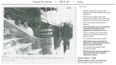
German Free School • 507 E. 10th • Austin Timeline o o o o o o o o o 1857-58: Construction of rammed earth building (directly south of project area), wood shingle roof 1872: Two-story addition to the north, constructed of limestone, with 1-story wood framed porch and balcony, wood shingle roof 1881: School closed, building became a residence 1901: Double gallery porch constructed with turned posts, turned balusters, and gingerbread trim; exterior stair, tin roof 1919: Fire destroyed much of the original building, but the limestone addition and porch was spared 1921: Second floor porch was screened 1948: Victorian-era porch removed and replaced with a Greek Revival porch with no balcony rails until at least 1965 1991: German Texas Heritage Society acquired the building 2022: GTHS seeks to remove the 1948 porch and rebuild the 1901 porch, including needed stair for egress. Historic Photo c. 1918 Double-gallery porch and staircase Photo courtesy of the Austin History Center German Free School • 507 E. 10th • Austin 1872: Northern (limestone) section of school constructed 1900: Single story wood- framed porch still shows on Sanborn Map 1901: Double gallery porch likely constructed as part of stone addition at east end of school 1921: upper level screened as a sleeping porch for tenants 1 ! 1949: Porch removed and replaced with existing Greek 4 Revival-styled porch - ; I ^ 1 ! 4 - ; I ^ German Free School • 507 E. 10th • Austin 1 ! 4 - ; I ^ The double gallery porch was constructed circa 1901, and screened-in 1921. It was removed in the 1948 renovation of the property by owner Kelly Stevens. The photo to the right shows two different patterns of turned balusters: one at the upper gallery, and one at the stair Historic Photos c. 1940 Double-gallery porch and staircase German Free School • 507 E. 10th • Austin Photo c. 1948 Original building in foreground, original porch still in place at 1872 addition Photo courtesy of the German Texas Heritage Society German Free School • 507 E. 10th • Austin Photo c. 1971 Greek Revival porch constructed ca. 1948 no railings present State marker on fence Photo courtesy of the Austin History Center PICH 06305 German Free School • 507 E. 10th • Austin EAST ELEVATION, 2022 German Free School • 507 E. 10th • Austin Rough outline of proposed reconstructed porch EAST ELEVATION, 2022 German Free School • 507 E. 10th • Austin NEW STAIR LOCATION German Free School • 507 E. 10th • Austin WEST ELEVATION, 2022 German Free School • 507 E. 10th • Austin EAST ELEVATION, 2022 German Free School • 507 E. 10th • Austin NORTH ELEVATION, 2022 As seen from 10th Street PROJECT INFORMATION LEGAL DESCRIPTION: Lot 6 and Lot 7, Block 114, original City of Austin, Travis County, Texas HISTORIC DESIGNATIONS: Austin Landmark, National Register of Historic Places, Recorded Texas Historic Landmark ZONING: CS-1-H YEAR CONSTRUCTED: 1858 and 1872 APPLICABLE CODES: 2021 IBC and IEBC LOT SIZE: 17,592 SQ. FT. OCCUPANCY: A-3 or B FLOOR AREA: 2,625 SQ. FT. [NET] CONSTRUCTION TYPE: IIIB SYMBOL LEGEND FFE 0" FFE OR GRADE ELEVATION AS NOTED ELEVATION (LARGE SCALE) D101 DOOR NUMBER W1 WINDOW NUMBER A WALL TYPE (PLAN VIEW) NEW WALL (PLAN VIEW) W E 1/A-401 ELEVATION (SMALL SCALE) STRUCTURAL SECTION DETAIL CL CENTERLINE PLAN/ ELEVATION DETAIL EQUAL DIMENSIONS IN LINE A-211 1 N S 1 A-211 1 A-211 LIST OF DRAWINGS ARCHITECTURAL A-000 A-100 A-110 A-120 A-121 A-122 A-210 A-310 A-510 A-511 A-901 A-902 A-903 S-001 S-002 S-003 S-101 S-201 S-202 COVER SHEET SITE PLAN DEMOLITION PLANS FOUNDATION & PAVING FIRST FLOOR AND FRAMING PLANS SECOND FLOOR AND ROOF PLANS ELEVATIONS SECTIONS RAILING & POST DETAILS DETAILS SPECIFICATIONS SPECIFICATIONS SPECIFICATIONS STRUCTURAL NOTES STRUCTURAL NOTES SPECIAL INSPECTIONS FOUNDATION, FLOOR & ROOF STRUCTURAL DETAILS STRUCTURAL DETAILS ABBREVIATIONS & # @ And Pound At Air Conditioning A/C ACOUST Acoustical ADD'L Additional ADJ AFF AHJ AHU APPROX Approximately ARCH ASTM American Society for Testing Adjacent Above Finish Floor Authority Having Jurisdiction Air Handling Unit Architect & Materials Equal Spacing, Equivalent EQ Equipment EQUIP EXH Exhaust EXST'G Existing Exterior EXT FAR FF(E) FIN FIXT FLR FT FTG FV FV HT Floor-Area Ratio Finished Floor (Elevation) Finish(ed) Fixture Floor Feet, Foot Footing Field Verify Field Verify Height Base Flood Elevation BFE Board BRD BLDG Building BDRM Bedroom BTM BTWN Between Bottom Cabinet Cubic Feet Control Joint Centerline Ceiling Closet Clear Column CAB CF CJ CL CLG CLO CLR COL COMP Composite CONC CONST Construction CONT COORD Coordinate, Coordination Critical Root Zone CRZ Cover CVR Cold Water CW Continuous Concrete Deep, Depth, Dryer Double D DBL DEMO Demolish, Demolition Double Hung DH Diameter DIA Diagonal, Diagonally DIAG Down DN Downspout DS Dishwasher DW Drawing DWG Drawer DWR East Each Expansion Joint Electric Meter Equal Spacing, Equivalent Equipment E EA EJ EM EQ EQUIP EXST'G Existing Exterior EXT Gauge GA Galvanized GALV General Contractor GC Ground Fault Circuit Interrupt GFCI Glass GL Gas Meter GM GPM Gallons Per Minute GR GRND Ground GSF GYP BD Gypsum Wall Board Gross Square Feet Grade Hose Bib Header HB HDR HDWR Hardware HORIZ Horizontal HR HT HTG HVAC Hour Height Heating Heat/Ventilation/ Air Conditioning Id Est (That Is) Inches Inaccessible Including Information Insulation Interior Joint Joist Kitchen I.E. IN INAC INCL INFO INSUL INT JNT JST KIT L LAM LAV LB(S) LF LP LT LVR Length Laminated Lavatory Pound(s) Linear Foot Light Pole or Lightning Protection Light Louver MFGR Manufacturer MAX Maximum MECH Mechanical M/E MEP Mechanical/Electrical Mechanical, Electrical, & Plumbing Minimum MIN MISC Miscellaneous MTD Mounted MTL Metal N NA NIC NO NSF NTE NTS North Not Applicable Not in Contract Number Net Square Feet Not to Exceed Not to Scale OC On Center OCEW On Center Each Way OP'G OVHD Overhead OZ Opening Ounce P&I PC PG PL PR PSF PSI PT PTD PVC PVMT PWD Provide & Install Photo Cell Page Plate or Plateline Pair Pounds Per Square Foot Pounds Per Square Inch Pressure Treated Painted Polyvinyl Chloride Pavement Plywood QTR Quarter Radius/Refrigerator Reflected Ceiling Plan R RCP RE/REF Reference REINF Reinforced REQ'D Required REQMT'S Requirements Revision REV Roofing RFG Room RM Rough Opening RO ROW Right of Way South Salvage Self-Adhering Underlayment S SALV SAU SCH'D Scheduled SECT SEP SF SHT SIM SHTG SK SMACNA Sheet Metal & Air Conditioning National Association, Inc. Specifications Section Seperate, Seperated Square Feet Sheet Similar Sheathing Sink Square Stainless Steel Steel SPECS SPEC'D Specified SQ SS STL STRUCT Structural Suspended SUSP Switch SW Symmetrical SYM Tongue & Groove Temporary, Tempered Thick Total T&G TEMP THK TOT TOW Top of Wall TRTD TYP Treated Typical Under Counter Under Counter Refrigerator Underwriter's Laboratory UC UCR UL UNFIN Unfinished UNO Unless Noted Otherwise Vapor Barrier Vertical Verify VB VERT VFY W Wide, Width, West, Washing Machine With Stackable Washer Dryer Wood W/ W/O Without W/D WD WDW Window WH WM WP WT Water Heater Water Meter Waterproofing Weight YD Yards GENERAL NOTES 1. 2. 3. 4. 5. All work shall be performed in a professional matter, and in accordance with the International Building Code, related trade codes, and applicable local codes, ordinances and laws. Contractor shall verity critical dimensions before beginning work. Do not scale drawings. Ask Architect for needed dimensions if not provided. Historic designation of this building requires the Contractor and his subcontractors to exercise special caution in executing the work to prevent unnecessary damage to historic features, conditions, or materials. Contractor shall inform all subcontractors and workmen of these requirements. The Contractor shall thoroughly example and familiarize himself with the requirements of the Contract Documents. Any conflicts shall be brought to the Architect's attention for resolution prior to the work being installed. Perform all work in a safe and conscientious manner to prevent injuries and damage to the building and workers. Contractor shall maintain OSHA Standards for job safety and worker protection, and comply with applicable state and local government requirements. 6. Building permitting will be coordinated by the Owner and Architect prior to construction. Contractor is responsible for all trade permits, inspections, and compliance requirements. 7. Maintain the building and site in a clean and orderly condition. 8. The Contractor shall visit the site of the proposed work and full acquaint himself with the existing conditions regarding site access, staging, parking limitations, security, and other aspects of constructibility. 9. The Contractor shall coordinate work between all trades in this contract to ensure a smooth and timely workflow. 10. All work to be warranted for one year from the date of Substantial Completion unless otherwise noted. DESIGN TEAM ARCHITECTURE O'CONNELL ARCHITECTURE, LLC TERESA O'CONNELL, AIA 3908 AVENUE B, SUITE 309 AUSTIN, TEXAS 78751 512|751-1374 STRUCTURAL ENGINEERING TSEN ENGINEERING JAMIE BUCHANAN, P.E. 210 BARTON SPRINGS ROAD, #250 AUSTIN, TEXAS. 78704 OWNER GERMAN TEXAS HERITAGE SOCIETY CHRISTOPHER MARKLEY, EXECUTIVE DIRECTOR 507 EAST 10th STREET AUSTIN, TEXAS. 78701 G E R M A N F R E E S C H O O L 3908 Avenue B, #309 Austin, Texas 78751 512|751-1374 NOT FOR CONSTRUCTION TERESA O'CONNELL #15432 L O O H C S E E R F N A M R E G 1 0 7 8 7 s a x e T n i t s u A t , t e e r t S h 0 1 . E 7 0 5 East 10th Street 68'11.04" S 71°07'00" E s p e t S Lot 7 h c r o g P tin xis E Lot 6 Block 114 g uildin y B r n o s a " 2 0 " E 9 1'5 0 ° 9 8'.0 N 1 2 1 y M r o t 2-S e c a r r e k T ric B s p e t S " " W 0 9'5 8'0 5 2 ° 1 8 S 1 Lot 5 Carport N 71°07'00" W 69'0" 20' Alley e et e r Str d Riv E. R e 1 SITE PLAN Scale: 1" = 20'-0" ISSUE DATE 95% CONSTRUCTION DOCS September 1, 2022 SHEET NAME COVER SHEET SHEET NUMBER A-000 4 9 7 4 9 6 4 9 8 4 9 2 4 9 1 4 8 9 4 8 8 East 10th Street 10th STREET r o n R o d I F o u n d 1 / 2 " (69.00') 68.52' S73°44'38"E (69.00') 69.21' N73°35'53"W C o n c W a l l F o u n d 1 / 2 " r o n R o d I S t o n e W a l l 503 502 504 501 500 505 506 498 499 4 9 8 . 4 ' . E l 0.8' El. 496.9' Brick Paving " 0 - ' 3 1 1/2 CRZ Full CRZ (69.00') 68.44' S73°22'17"E Stone Flags s r e s i R 9 #114 Planting 496 r o n R o d C a p p e d I S e t (69.00') 68.44' S73°22'17"E r o n R o d I F o u n d 1 / 2 " C o n c S t e p s ' 2 8 . 7 2 1 ( 1 2 8 . 0 0 ' ) ' E " 2 0 6 4 ° 6 1 N Wood Deck i j A d o n n g B u i i l i d n g 507 508 509 510 511 5 1 2 513 514 515 516 Metal Shed STORAGE BUILDING Fin. Fl. 517.8' #85 518 Asphalt Parking Lot 7 5 1 9 5 2 0 5 2 1 5 2 2 5 2 3 #140 4 2 5 (69.00') N73°26'28"W 68.99' r o n R o d I F o u n d 1 / 2 " 20' ALLEY E l . 4 9 8 . 9 ' Lower Fin. Fl. 499.0' 2 Risers El. 495.4' El. 496.1' 2 Risers g n i t n a P l 4 9 8 4 9 7 g n i v a P k c i r B El. 497.1' El. 497.7' El. 498.4' g n i t n a P l E l . 4 9 9 . 6 ' 500 Stone Flags Planting 4 9 7 498 LIMITS of CONSTRUCTION 1 2 8 . 1 0 ' ( 1 2 8 . 0 0 ' ) S 1 6 ° 1 8 1 3 " W ' Mid Fin. Fl. 501.4' Steps Upper Fin. Fl. 510.4' g n d i l i u B y r n o s a M y r o t S 2 E l . 5 1 0 . 2 ' e c a r r e T k c i r B Upper Fin. Fl. 510.4' Grass Lawn 5 0 0 . 9 ' . E l s r e s i R 3 El. 502.7' 501 Stone Steps Lot 6 Block 114 g n i v a P k c i r B 503 Grass Lawn Critical Root Zone Lot 5 t e e r t S r e v i R d e R . E #288 Planting s p e t S 5 0 3 . 8 ' 5 0 5 . 0 ' . E l . E l 1/2 Critical Root Zone Wood Shed 0.36' Wood Shed 5 1 0 5 1 0 . 1 ' . e l Existing Carport ! 8 1 5 7 1 5 6 1 5 515 514 513 512 1 1 5 5 1 0 ! 9 0 5 CONSTRUCTION SITE ACCESS ! ! 20' Alley (69.00') N73°26'28"W 69.01' 509 5 0 7 5 0 8 5 0 6 5 0 5 5 4 0 #271 TREE SURVEY 85 16" Pecan 114 33" Live Oak 140 42" Live Oak 271 13" China Berry 288 37", 28" Live Oak 1 SITE PLAN Scale: 1" = 10'-0" 3908 Avenue B, #309 Austin, Texas 78751 512|751-1374 NOT FOR CONSTRUCTION TERESA O'CONNELL #15432 1 0 7 8 7 s a x e T n i t s u A t , t e e r t S h 0 1 . E 7 0 5 L O O R H E C S D E E R R I F V N E A M R R S E G T R E E T ISSUE DATE 95% CONSTRUCTION DOCS September 1, 2022 SHEET NAME SITE PLAN SHEET NUMBER A-100 Remove Porch complete with Columns and Roof Limits of Construction Remove Iron Railing Panels and Salvage to owner Remove Historic Markers and Corner Stone for Relocation 3 WEST ELEVATION Scale: 1/4" = 1'-0" 3908 Avenue B, #309 Austin, Texas 78751 512|751-1374 NOT FOR CONSTRUCTION TERESA O'CONNELL #15432 L O O H C S E E R F N A M R E G 1 0 7 8 7 s a x e T n i t s u A t , t e e r t S h 0 1 . E 7 0 5 ISSUE DATE 95% CONSTRUCTION DOCS September 1, 2022 SHEET NAME DEMO DRAWINGS SHEET NUMBER A-110 Remove Railing and Coping Stones Remove Porch with Roof Remove Exist. Steps Remove Brick Paving & Concrete Slab to excavate for new Footings Down Remove Exist. Steps, salvage Iron Railings Salvage Iron Railing Sections to Owner, typical for all 2 SECOND FLOOR DEMOLITION PLAN Scale: 1/4" = 1'-0" Remove lower Stone Wall and excavate for new Footing Remove Paving & Steps for rebuilding n w o D Down n w o D Down Down 1 GROUND FLOOR DEMOLITION PLAN Scale: 1/4" = 1'-0" Edge of Terrace Wall Limits of Slab Removal 1'-6" CL Simpson Post Base on Reinf. Concrte Footing – see structural dwg.s Planting Bed CL 6 1/2" 12'-1 1/2" Step Footing CL CL Post Base, Typ. Limits of Slab Removal 10'-0" CL CL " 2 / 1 5 - ' 5 Footer for Bottom of Stair 2 A-520 New Poured Concrete Footing, see Structural dwg.s El. 501.4' El. 500.0' Limits of New Steps to Restroom " 1 1 - ' 3 " 2 / 1 6 - ' 4 " 9 " 4 - ' 4 ± Exist. Brick Paving " 8 - ' 8 Remove and Rebuild Steps in Stone as required for construction of new Foundations Repair/Patch Paving to match existing CL 3" 10'-0" Planting Bed ex. limestone slab curb n w o D El. 499.0' El. 498.9' 9'-9 1/2" 10'-0" 8'-0" Rebuild Steps to align with new Porch New Limestone Curb at Planting Bed, ea. side, to align with Porch Posts infill and Patch walks as required Rebuild landscape wall with return Remove and rebuild stone curb to align with stair Planting Bed ex. 12" wide stone edge ex. landscape walls Exist. Brick Paving El. 499.6' " 0 - ' 3 ± Exist. Grass El. 498.1' El. 497.1' Exist. Brick Paving El. 496.1' El. 495.4' Down Down Down Exist. Stone Paving Note: New Paving for area below porch and rebuilt steps shall be Limestone flags. Existing Brick below Porch shall be salvaged for use to patch and repair existing brick walks adjacent to the porch and steps. 1 FOUNDATION & PAVING PLAN Scale: 1/2" = 1'-0" 3908 Avenue B, #309 Austin, Texas 78751 512|751-1374 NOT FOR CONSTRUCTION TERESA O'CONNELL #15432 L O O H C S E E R F N A M R E G 1 0 7 8 7 s a x e T n i t s u A t , t e e r t S h 0 1 . E 7 0 5 ISSUE DATE 95% CONSTRUCTION DOCS September 1, 2022 SHEET NAME FOUNDATION & PAVING PLAN SHEET NUMBER A-120 6'-7" 1'-0" 1'-0" 1'-0" 1'-0" 1'-0" See Strucutral Dwg.s for All Member Sizes " 3 - ' 5 " 0 - ' 2 3 Risers @ ±6" ea. 11" 5'-8" 5 Risers @ ±5-1/2" ea. " 6 - ' 3 S l o p e t o d r a i n Black Steel Handrail 3 LAYOUT FOR STEPS Scale: 1/2" = 1'-0" 4'-8" 12'-8 1/4" " 8 / 1 1 - ' 4 UP 5'-0" 5'-0" g n i r o o l F G & T . Q E . Q E . Q E . Q E 6 3/4" 12'-1 1/2" 10'-0" 10'-0" 10'-0" 2 3/4" 2 PORCH CEILING FRAMING Scale: 1/4" = 1'-0" 3908 Avenue B, #309 Austin, Texas 78751 512|751-1374 NOT FOR CONSTRUCTION TERESA O'CONNELL #15432 L O O H C S E E R F N A M R E G 1 0 7 8 7 s a x e T n i t s u A t , t e e r t S h 0 1 . E 7 0 5 ISSUE DATE 95% CONSTRUCTION DOCS September 1, 2022 SHEET NAME GROUND FLOOR PLAN SHEET NUMBER A-121 3 A-121 Half Post at face of Wall 2 A-310 Half Post at face of Wall 1 A-310 ex. landscape walls Turned Post Remove brick paving for new work, install new limestone flags at steps & paved area below Porch UP Turned Newel post for handrail 5-1/4" x 5-1/4" Turned Wood Posts, typical " 8 - ' 8 12'-1 1/2" 9'-11 7/8" 10'-0" 10'-0" 2 5/8" ex. landscape wall 42'-10 1/2" Rebuild Steps to align with new Porch ex. landscape wall 1 GROUND FLOOR PLAN Scale: 1/4" = 1'-0" Hip Edge of Main Roof Flat Seam Terne Metal Roof Porch Roof Edge 2 PORCH ROOF PLAN Scale: 1/4" = 1'-0" 2 A-310 Brick at Terrace Wood Porch Flooring 1 A-310 1'-0" - 3 7 / 8 " 3 ' DN 4'-8 1/8" Extend exist. iron rail to meet new porch rail " 4 / 3 8 - ' 3 " 0 - ' 4 " 8 / 7 3 T&G Porch Flooring, all boards shall be single lengths 5-1/4" Turned Porch Posts, typical Wood Guardrail, see drawings Sheet A-510 1 SECOND FLOOR PLAN Scale: 1/4" = 1'-0" 3908 Avenue B, #309 Austin, Texas 78751 512|751-1374 NOT FOR CONSTRUCTION TERESA O'CONNELL #15432 L O O H C S E E R F N A M R E G 1 0 7 8 7 s a x e T n i t s u A t , t e e r t S h 0 1 . E 7 0 5 ISSUE DATE 95% CONSTRUCTION DOCS September 1, 2022 SHEET NAME SECOND FLOOR & ROOF PLAN SHEET NUMBER A-122 3 3 A-511 Sawn Brackets above each Post, with 2x @ equal spaces between Flat Seam Terne Metal Roof 4 A-511 Elev. 510.2' " 6 - ' 7 ± Elev. 502.7' Open Riser Staircase with Turned Balusters Elev. 501.4' Elev. 499.6' 2 WEST ELEVATION Scale: 1/4" = 1'-0" Elev. 498.9' Elev. 495.4' Half-Round Gutters Custom 5-1/2" SQ. Turned Porch Posts Turned Balusters Fancy Sawn Scrollwork Porch Brackets, as per detail Sheet A-520 New Downspout Relocate Corner stone, new location TBD Sawn Brackets at Wall, Porch Corner, & midpoint Sawn Brackets at Wall, Porch Corner, & midpoint Turned Porch Posts New Downspout Exist. Terrace Fancy Sawn Scrollwork Brackets, see Detail 4/A-520 Turned Posts Turned Ballusters New Downspout Half-Post at Wall, Plain Rectangular Stock 5-1/2" x 3", with chamfered corners Elev. 510.4' Elev. 501.4' Exist. Downspout SECOND FLOOR Elev. 510.4' GROUND FLOOR Elev. 499.0' 3 PARTIAL SECTION/NORTH ELEVATION Scale: 1/4" = 1'-0" Reinf. Concrete Footings, typical 1 SOUTH ELEVATION Scale: 1/4" = 1'-0" 3908 Avenue B, #309 Austin, Texas 78751 512|751-1374 NOT FOR CONSTRUCTION TERESA O'CONNELL #15432 L O O H C S E E R F N A M R E G 1 0 7 8 7 s a x e T n i t s u A t , t e e r t S h 0 1 . E 7 0 5 ISSUE DATE 95% CONSTRUCTION DOCS September 1, 2022 SHEET NAME ELEVATIONS SHEET NUMBER A-210 2 x 4 Rafters 1 A-310 12 2 1 x 6 T&G board Roof Sheathing 3 A-511 Flat Seam Terne Metal Roof over Building Paper 2 A-310 2 x 6 Roof Rafters Outline of Posts at Exterior Elevation 3-1/8" post below rail Nom. 3-1/8" x 8-1/4" Glu-lam Member Guardrail 3-1/8" sq. Post at Corners, chamfer top at 30° 1'-0" Corner at Rail Guardrail 3-1/8" post below rail 5" typ. NOTE: Porch Decking rests on Stone Ledge at Building Wall 4" x 10" timber Beam, painted finish Bracket sawn from 6/4 stock 5-1/4" Sq. Turned Wood Posts Nom. 3-1/8" x 9-5/8" Appearance Grade Glu-Lam timber, painted finish Nom. 5-1/8" x 9-5/8" Member 1 A-511 3-1/8" sq. Post at Corners, chamfer top at 30° " 6 - ' 3 6/4 Tongue & Groove Porch Flooring 5'-0" " 8 / 7 0 - ' 7 h c a e " 9 6 ± @ . s r e s i R 0 2 = " 2 / 1 5 - ' 1 1 ± 2 A-510 1'-0" Guard below Stair welded from 3/4" sq. steel tube 1 STAIR SECTION Scale: 1/2" = 1'-0" " 0 - ' 3 " 8 / 7 6 11" " 6 - ' 1 4'-7" 17'-5" = 19 Treads @ 11" each 5 Risers @ ±5-1/2"ea. 3" Square Bottom Post Extend Stringer to Post 3 Risers @ ±6" ea. Warp Paving to meet grades in angle of Steps below stair See Structural for Footings 6" 12'-0 1/2" 10'-0" 3'-0" " 0 - ' 3 2 PORCH CROSS SECTION Scale: 1/2" = 1'-0" 3908 Avenue B, #309 Austin, Texas 78751 512|751-1374 NOT FOR CONSTRUCTION TERESA O'CONNELL #15432 L O O H C S E E R F N A M R E G 1 0 7 8 7 s a x e T n i t s u A t , t e e r t S h 0 1 . E 7 0 5 ISSUE DATE 95% CONSTRUCTION DOCS September 1, 2022 SHEET NAME PORCH SECTION SHEET NUMBER A-310 NOTE: Porch guardrail balusters and Staircase handrail balusters are different in profile! R 1/8" 4" dia. Sphere 2 1/4" 4 " 4 / 1 6 " 2 / 1 2 - ' 1 1 1/4" CLCL 5 1/2" 5 1/2" 1 1/4" " 0 - ' 3 CL " 8 / 3 7 2 1/4" 3" 1 5/8" 5 1/4" 4" " 4 / 1 1 " 8 / 1 6 " 4 / 3 1 " 4 / 1 1 4 HANDRAIL Scale: Actual Size Bracket from 6/4 Stock Volute End at Handrail Extension R 1 3/4" CL " 5 - ' 4 1'-0" 3" Square Railing Bottom Post, with beaded corners 6" dia. Sphere 1" thk. Risers 5/4" thk. Hardwood Treads Clip Angle Extended Stringer Miter into Post " 6 - ' 3 " 3 " 8 / 7 6 " 4 / 1 6 - ' 1 " 8 / 3 8 " 2 / 1 3 " 2 " 1 " 2 / 1 " 4 / 1 2 " 1 " 4 / 1 0 1 " 1 1 - ' 1 " 8 / 7 1 1 " 4 / 3 " 8 / 3 6 " 8 / 7 4 1/8" R 3/4" 5 1/4" 3908 Avenue B, #309 Austin, Texas 78751 512|751-1374 NOT FOR CONSTRUCTION TERESA O'CONNELL #15432 L O O H C S E E R F N A M R E G 1 0 7 8 7 s a x e T n i t s u A t , t e e r t S h 0 1 . E 7 0 5 ISSUE DATE 95% CONSTRUCTION DOCS September 1, 2022 SHEET NAME DETAILS SHEET NUMBER A-510 3 PORCH GUARD RAIL Scale: 3" = 1'-0" 2 STAIR HANDRAIL Scale: 3" = 1'-0" 1 TURNED PORCH POST Scale: 3" = 1'-0" 2" 1 1/8" 3" 5 3/8" 2 1/8" R 1/8" typ. " 2 " 8 / 7 1 R 1" R 5/8" R 3 7/8" Flat Seam Terne Metal Roof over Building Paper 1 x 6 T&G board Roof Sheathing " 8 / 3 6" Bracket sawn from 6/4 stock 4 X 10 Header (or app'v'd. equal) Rounded profile got out of 1x4 stock with plane or spokeshave 2 x 6 Roof Rafters 2 x 4 Ledger, lagged into Header 4 3/4" ±2 1/4" 3 / 4 " 6 0 . 0 0 ° 1 1/2" 2 5/8" 3/4" 5 EAVE BRACKET LAYOUT Scale: Half Actual Size " 8 / 7 " 8 / 3 4 " 8 / 1 2 " 2 / 1 7 " 4 / 1 1 1 " 2 " 8 / 1 1 " 8 / 3 3 " 8 / 3 1 " 8 / 3 3 R 2 3/4" 2" 1 7/8" " 8 / 1 2 1/2" 4 SCROLLWORK BRACKET LAYOUT Scale: Half Actual Size Brackets shall be sawn from 6/4 clear stock 3 EAVE DETAIL Scale: 3" = 1'-0" Edge of old Columns 8'-8" from face of Building New Porch Post Simpson Post Base – see structural dwg.s 498.7' New Stone Paving Mortar setting Bed Exist. Slab Reinforced Concrete Grade Beam – see structural dwg.s Remove exist. Coping stone and rail New Stone Pavers at edge Extend Floor to provide 1/4" clear Wood Porch Flooring 3"x 5" Steel Angle, lag bolted into Girder Carlisle WIP 300HT Waterproofing Membrane Lam Girder at Porch End 3 1/2" Exist. Terrace Wall 2 PORCH EDGE & STEPS Scale: 1 1/2" = 1'-0" 1 THRESHOLD DETAIL Scale: 1 1/2" = 1'-0" line of exist. steps to be removed 497.1' ex. walk New New stone steps 3908 Avenue B, #309 Austin, Texas 78751 512|751-1374 NOT FOR CONSTRUCTION TERESA O'CONNELL #15432 L O O H C S E E R F N A M R E G 1 0 7 8 7 s a x e T n i t s u A t , t e e r t S h 0 1 . E 7 0 5 ISSUE DATE 95% CONSTRUCTION DOCS July 31, 2022 SHEET NAME DETAILS SHEET NUMBER A-511 3908 Avenue B, #309 Austin, Texas 78751 512|751-1374 NOT FOR CONSTRUCTION TERESA O'CONNELL #15432 L O O H C S E E R F N A M R E G 1 0 7 8 7 s a x e T n i t s u A t , t e e r t S h 0 1 . E 7 0 5 ISSUE DATE 95% CONSTRUCTION DOCS September 1, 2022 SHEET NAME SPECIFICATIONS SHEET NUMBER A-901 Contractor is expected to monitor the work of all trades to prevent unnecessary or otherwise avoidable damage to original features, condi6ons, or materials. SUBCONTRACTORS: This project an6cipates the use of subcontractors to perform aspects of work. These persons or en66es will contract directly with the Contractor to perform their defined scope of work. The Contractor will furnish in wri6ng to the Owner through the Architect the names of persons or en66es (including those who are to furnish materials or equipment fabricated to a special design) proposed for each principal por6on of the work. Should the Architect or Owner iden6fy a reasonable objec6on to a proposed subcontractor within 14 days, the Contractor shall find another acceptable subcontractor to perform the work in ques6on. As a result, contract adjustments for cost and 6me may be required. DRESS AND CONDUCT: Minimum street dress shall include shoes, long pants or shorts, and shirt at all 6mes. Amplified music, foul language, and/or smoking will not be permijed on the site. Do not allow personal trash or debris to accumulate on site – dispose of all waste by the end of each work day. 01200 PROJECT ADMINISTRATION, SUBMITTALS, PAYMENTS, AND CLOSEOUT: SCOPE: This sec6on covers highlights of project administra6on, payments, and project closeout, and is intended as a supplement to the Uniform General Condi6ons and Supplemental Condi6ons. SUBMIT: 1.Insurance 2.Construc6on Schedule 3.Schedule of Values 4.Applica6ons for Payment 5.Record Documents 6.Substan6al Comple6on Punch List 7.Extra Stock and Materials CONSTRUCTION SCHEDULE: should indicate: Milestone start-up, span, and comple6on dates for defined scopes of work. The construc6on period is an6cipated to be 180 days from date of contract signing to Final Comple6on. Mock up review dates Substan6al Comple6on Final Comple6on Provide for a reasonable number of inclement weather days based upon the past 5 years of weather performance in Aus6n for the an6cipated period of construc6on. SCHEDULE OF VALUES: The Schedule of Values shall break down project costs in accord with the following minimum categories OR APPROVED EQUAL. Greater detail may be provided at Contractor’s discre6on. 1.Project Administra6on, (including Temporary Facili6es and Temporary Protec6on) 2.Selec6ve Demoli6on 3.Site Work 4.Founda6on 5.Concrete Stairs, Sidewalks, and Pads 6.Masonry 7.Metal Handrails 8.Wood Framing 9.Finish Carpentry, Repair of Exis6ng Windows and Doors 10.Roofing, Gujers and Downspouts 11.Pain6ng APPLICATIONS FOR PAYMENT: Submijals: Payments to the Contractor shall be made twice per month as s6pulated in General Condi6ons of the Contract for Construc6on (AIA document A201 or approved equal). Contractor shall submit one dram electronically for review and one final copy of each Applica6on for Payment to the Architect for cer6fica6on. Retainage: The Owner will retain 5 percent (5%) of each payment un6l Project Comple6on. Timeliness of Payment: Payment of approved Applica6ons for Payment will be made within 10 working days of approval. 01200 PROJECT MEETINGS: Conduct progress mee6ngs at the Project site at regularly scheduled intervals. Mee6ngs shall include a review of Contractor's payment request when applicable, review of progress in rela6onship to schedule, review of mock-ups, and discussion of upcoming work. Coordinate dates of mee6ngs with prepara6on of the payment request. Provide an updated Progress Schedule at each Progress Mee6ng. Advise the Architect and Owner of scheduled mee6ng dates. PROJECT COORDINATION: Coordina6on: Contractor shall coordinate work between all trades in this contract. Any conflicts shall be brought to the Architect’s ajen6on prior to the work being installed for resolu6on. Verifica6on of dimensions: Contractor shall check and verify all dimensions, building eleva6ons, and condi6ons both exis6ng and new. Report any and all discrepancies to the architect before beginning any phase of work. Do not scale drawings. Contractor is responsible for field dimensions and measurements including slope. Protec6on of building and site: contractor shall protect all surfaces not scheduled for work under this contract. Any damage to the exis6ng structure and site that occurs following the no6ce to proceed shall be corrected to pre-construc6on condi6on at no expense to the owner. Contractor shall keep the building secure and weather-6ght at all 6mes. Safety: perform all work in a safe and conscien6ous manner to prevent injuries and damage to the building, its contents, or its surroundings. Contractor shall maintain OSHA standards for job safety and worker protec6on and comply with all requirements of the Health And Safety Code Of Texas, Chapter 756, Subchapter c for adequate trench protec6on, barricades, signs, etc. Storage: establish a secure storage area for all items marked "remove for reinstalla6on" or "remove and salvage". Storage is to be a protected, secure, weatherproof loca6on to prevent damage to materials. REQUESTS FOR INFORMATION: The Contractor may request clarifica6ons and instruc6ons regarding the Contract Documents. A Request for Informa6on (RFI) is a means for which the Contractor shall use to request such guidance and instruc6on from the Architect. These are to be sequen6ally numbered and an RFI register shall be maintained by the Contractor. This register shall be updated and regularly scheduled progress mee6ng. 01300 SUBMITTALS: CoordinaIon: Coordinate prepara6on and processing of submijals with performance of the Work. Transmit each submijal to the Architect sufficiently in advance of scheduled performance of related construc6on ac6vi6es to avoid delay. A.Coordinate each submijal with fabrica6on, purchasing, tes6ng, delivery, other submijals and related ac6vi6es that require sequen6al ac6vity. B.Coordinate transmijal of different types of submijals for the same element of the Work and different elements of related parts of the Work so that processing will not be delayed by the Architect or Engineer’s need to revise submijals concurrently for coordina6on. C.The Architect reserves the right to withhold ac6on on a submijal requiring coordina6on with other submijals un6l related submijals are received. D.Submijals received amer installa6on of the submijed material or product is complete will be rejected and the work shall be removed. SubmiUal PreparaIon: Place a permanent label or 6tle block on each submijal for iden6fica6on. Indicate the name of the firm or en6ty that prepared each submijal on the label or 6tle block. Include: Project 6tle, name of owner, name of contractor, name of architect, date of submijal, specifica6on sec6on referenced, drawing details where appropriate, and contractor cer6fica6on of accuracy. In the submijal and construc6on process, the Contractor is responsible for: A.Dimensions, which shall be confirmed and correlated at the job site B.Fabrica6on processes and techniques of construc6on C.Coordina6on of work with that of all other trades D.Sa6sfactory performance of work under this contract. Product Data: Provide where requested in specifica6ons. Product Data to includes printed informa6on such as manufacturer’s installa6on instruc6ons, catalog cuts, standard color charts, roughing-in diagrams and templates, standard wiring diagrams and performance curves. A.Mark op6ons available to the project B.Mark selec6ons requiring architectural or engineering confirma6on C.Do not submit MSDS sheets – this informa6on is for contractor use, not the architect. Samples: Where specified, submit Samples physically iden6cal with the material or product proposed for use; submit full-size, fully fabricated Samples, cured and finished in the manner specified. Coordinate Architect's review of required Samples with regularly scheduled Project Mee6ngs, as indicated in Construc6on Schedule. Mock Ups are intended to fully and accurately represent the proposed installed quality, detailing, and installa6on techniques to be used in the Work. Coordinate Architect's review of required Mock Ups with regularly scheduled Project Mee6ngs, as indicated in Construc6on Schedule. Process and AcIons: The Architect, in consulta6on with the Owner, will accept, provide comments, or reject submijals, and convey that informa6on back to the Contractor. 01380 – CONSTRUCTION PHOTOGRAPHS GENERAL Submit digital images to meet the following requirements CONTENT: A.Pre-construc6on photographs representa6ve of all condi6ons. B.Images of u6li6es and systems that will be concealed below slabs, behind walls, and above ceilings before they are covered up. C.Photos of condi6ons requiring input from others as needed during the course of construc6on. D.Final comple6on photographs representa6ve of all areas. QUALITY: A.Color images with a minimum resolu6on of 3264 x 2448 pixels (typical of current model iPhone) B.Focus, ligh6ng and composi6on as needed to convey intended informa6on FORMAT: Name each image using the following format: GFS_YEAR-MM-DD_View-## A.View is a brief descrip6on of the image B.## is a sequen6al number for the images taken on that date. MEDIA: Submit digital photographs on a dedicated flash drive that is PC-and MAC-compa6ble. Clearly label storage device GFS-CONSTRUCTION PHOTOGRAPHS (DATE) TIME: Submit photographs according to the following schedule: A.Pre-Construc6on Photographs shall be submijed and accepted within one month of project start up B.Progress and Project Comple6on photographs shall be submijed and accepted prior to Final Project Close Out. C.Photographs as needed for communica6on throughout the course of construc6on shall be submijed on an “as needed” basis. 01600 CUTTING AND PATCHING: SCOPE General Contractor shall be responsible for all cuvng and patching that is required for the comple6on of any subcontractor's work. This shall include all necessary blocking and framing. Blocking/patching material shall be of solid wood of same species and size of adjacent material. Report any unexpected findings to Architect immediately upon discovery. 01700 PROJECT CLOSEOUT EXTRA STOCK AND MATERIALS: Convey extra stock to Owner at Substan6al Comple6on, including: A.Architectural woodwork, including spare molding, flooring, balusters and rail sec6ons B.Paint C.Stone remnants RECORD DOCUMENTS: During the construc6on period, maintain a complete set of Contract Drawings, Shop Drawings, Coordina6on Drawings, Addenda, Submijals, and Project Correspondence at the jobsite for documen6ng work during construc6on. Mark these Drawings to indicate the actual installa6on where the installa6on varies appreciably for the installa6on shown originally. Give par6cular ajen6on to informa6on on concealed elements that would be difficult to iden6fy or measure and record later. Items required to be marked include but are not limited to: A.Dimensional changes to the Drawings. B.Revisions to details shown on the Drawings. C.Changes made by Change Order. D.Details not on original Contract Drawings. SUBSTANTIAL AND FINAL COMPLETION: Scheduling of visits rela6ng to Substan6al and Final Comple6on shall be at the wrijen no6fica6on of the General Contractor as per the General Condi6ons. Project Closeout will be accomplished with the cer6fica6on by the Architect of the General Contractor's Final Applica6on for Payment. General Contractor must submit prior to Project Closeout: A.Contractor’s warranty B.Manufacturer’s warran6es C.maintenance instruc6ons D.equipment manuals E.extra materials F.record documents G.building permit documenta6on including Cer6ficate of Occupancy 01790 WARRANTIES: SCOPE: The Contractor shall guarantee all work under this Contract against defects in material and workmanship for a minimum period of one (1) year from the date of Substan6al Comple6on, and shall replace any work showing defects during this guarantee period without expense to the Owner. Where guarantees or warran6es for longer terms are wrijen into, required by, or referred to in any Division of these specifica6ons, they shall apply. Provide Owner with extended material warran6es at Project Closeout in the following sec6ons Sec6on 07611 Metal Roofing Sec6on 09900 Exterior Pain6ng 02300 EARTHWORK: SCOPE: A.Protect Heritage Trees in yard. B.Verify soundness of all downspout connec6ons to subgrade drainage system. C.Grade yard to provide posi6ve drainage away from building. JOB CONDITIONS: Barricade open excava6ons occurring as part of this work and post with signage and/or warning lights as recommended by authori6es having jurisdic6on. Protect structures, u6li6es, trees, sidewalks and plan6ng beds to remain from damage caused by sejlement, lateral movement, undermining, washout and other hazards created by earthwork opera6ons. Bulk Materials: Do not dump or store bulk materials near structures, u6li6es, walkways and pavements, or on exis6ng turf areas or plants. Provide erosion-control measures to prevent erosion or displacement of bulk materials; discharge of soil-bearing water runoff; and airborne dust reaching adjacent proper6es, water conveyance systems, or walkways. PROTECTION OF EXISTING TREES: Protect all exis6ng trees and other vegeta6on in the work area against unnecessary cuvng, breaking or skinning of roots, skinning or bruising of bark, smothering of trees by stockpiling construc6on materials or excavated materials within drip line, excess foot or vehicular traffic, or parking of vehicles within drip line. Provide temporary guards to protect trees and vegeta6on. Heritage Tree: Live oak trees in sideyard are protected by the City of Aus6n tree ordinance. Construct a 4’ chain link fence at the perimeter of the ½ Cri6cal Root Zone (marked CRZ on A-101). Water the tree on a regular basis in 6mes of low precipita6on throughout construc6on. SUBGRADE DRAINS: Determine the condi6on of the exis6ng downspout drain system and report findings to Owner and Architect. Coordinate repairs if needed before work con6nues. Subgrade drain system work may be required. If so, they will be considered as an added cost. UTILITIES: Locate all exis6ng underground u6li6es before beginning work. Maintain all exis6ng u6li6es not indicated to be removed. Coordinate with u6lity companies to temporarily shutoff services during excava6on if lines are ac6ve. MULCH: Provide Landscaper’s Mix mulch or approved equal as needed for heritage tree protec6on. Apply 3” of mulch around ½ Cri6cal Root Zone, and maintain throughout the course of the project. INSTALLATION GRADING: Uniformly grade areas to a smooth surface, free from irregular surface changes. Comply with compac6on requirements and grade to cross sec6ons, lines, and eleva6ons indicated. A.Provide a smooth transi6on between exis6ng adjacent grades and new grades. B.Cut out som spots, fill low spots, and trim high spots to conform to required surface tolerances. C.Avoid any impacts to ¼ Cri6cal Root Zone of the Heritage Tree. D.Do not disturb more than 4” of topsoil within the ¼ - ½ Cri6cal Root Zone of the Heritage Tree. Slope grades to direct water away from buildings and to prevent ponding. Finish subgrades to required eleva6ons within the following tolerances: Lawn or Unpaved Areas: Grade to drain away from the house at 8% slope Repair and reestablish grades to specified tolerances where completed or par6ally completed surfaces become eroded, rujed, sejled, or lose compac6on due to subsequent construc6on opera6ons or weather condi6ons. Sejling: Where sejling occurs during the Project correc6on period, remove finished surfacing, backfill with addi6onal approved material, compact, and reconstruct surfacing. Restore appearance, quality, and condi6on of finished surfacing to match adjacent work, and eliminate evidence of repair to the greatest extent possible. 02410 SELECTIVE DEMOLITION SCOPE Includes full removal and disposal of the following items and elements: A.Exis6ng wood porch and roof B.Steps to restroom C.Exis6ng concrete founda6on D.Brick paving below exis6ng porch Includes removal and salvage for reinstalla6on of the following items and elements: A.Iron railings and stair rails B.Exis6ng Corner Stone and Historical Markers C.Stone paving Includes removal and salvage to Owner of the following items and elements: A.Iron railing sec6ons DEMOLITION requires that the selec6ve removal, salvage, or reinstalla6on of certain elements of work be supervised or performed by the en6ty responsible for subsequent repair and restora6on. PROVIDE AND INSTALL temporary weather-6ght protec6on for any parts of the exterior wall, roof, windows and doors that are open 01010 SUMMARY OF THE WORK SCOPE: The extent of work covered in this contract is shown on the drawings in these specifica6ons, and includes: 1.Removal of the exis6ng 1950s-era porch, paving, steps and walks below porch; 2.New concrete founda6ons for the new porch and stair; 3.New double-gallery exterior porch and stair reconstructed from historic photographs; and 4.New masonry paving and masonry wing walls within work area. The Work will be constructed under a single prime contract. Project Loca6on: German-Texan Heritage Society, 507 E. 10th Street, Aus6n, TX 78701 OWNER: A.The Owner referred to in these Contract Documents is German-Texan Heritage Society, as represented by Christopher Markley, Execu6ve Director, 507 E. 10th Street, Aus6n, TX 78701 ARCHITECTURAL AND ENGINEERING: A.Architecture: O’Connell Architecture, LLC, as represented by Tere O’Connell, AIA, 3908 Avenue B, Room 309, Aus6n, Texas 78751. Contact informa6on: 512/751-1374, tere@ocpreserva6on.com B.Structural Engineering: Tsen Engineering, LLC, as represented by Jamie Buchanan, P.E., 210 Barton Springs Road, #250, Aus6n, Texas 78704. WORK IN HISTORIC STRUCTURES A.General: Historical classifica6on of this building requires Contractor to exercise special cau6on in execu6ng all stages of work to prevent unnecessary damage to historical features, condi6on, or materials. B.Contractor shall meet with the architect and develop a plan for protec6on of the adjacent historic construc6on. C.Contractor to apprise all sub-contractors and workmen of special precau6ons required when working with historic buildings. D.Contractor to monitor the work of all trades to prevent unnecessary or otherwise avoidable damage to historical features, condi6ons, or materials. E.Contractor shall immediately no6fy Architect and Owner as concealed historical condi6ons are uncovered during the course of the work and shall allow and facilitate the documenta6on of those condi6ons. F.Governing Preserva6on Requirements: The German-Texan Heritage Society building is subject to the provisions of the Secretary of the Interior’s Standards for Rehabilita1on. This project must comply with requirements as administered by the Texas Historical Commission (THC) to qualify for state and federal tax credits. The THC has authority to review the progress and comple6on of the Work. SITE AVAILABILITY Make the site available and accessible to representa6ves of the Texas Historical Commission upon request and as required within these specifica6ons. CONTRACTOR USE OF PREMISES: Limit use of site to areas impacted by work defined in contract documents. Protect all landscaping to remain. Temporary FaciliIes Portable Toilet: Locate portable toilet at least 20’ away from all structures and away from the front yard, in a serviceable loca6on. Schedule regular maintenance of portable toilets to prevent disrup6on or inconvenience to the Owner. Temporary Office: Contractor may supply their own desk and will provide all tools and equipment as needed to complete the project. Enclosure Fencing for ConstrucIon Staging Area: At Contractor’s discre6on, provide galvanized 2-inch, chain link fencing 6-feet high with galvanized steel pipe posts, 1-1/2" I.D. for line posts and top posts and 2-1/2" I.D. for corner posts. Provide 6-foot high gates fabricated from galvanized steel pipe and galvanized 2-inch chain link fabric fencing as required for access; gates to be secured with locks and one key to be provided to Owner. Material storage is allowed with prior Owner approval when kept in an orderly and protected manner at the east side of the property. CommunicaIon Services: Provide Project Superintendent/ Manager with con6nuous access to internet and cell phone service during working hours. Standards: Comply with NFPA Code 241, "Building Construc6on and Demoli6on Opera6ons", ANSI-A10 Series standard for "Safety Requirements for Construc6on and Demoli6on.” UIliIes: Owner shall provide access to electrical service and water for Contractor use. Contractor shall provide all hoses and OSHA compliant power cords as needed to complete the work. Do not allow water to run or drip during construc6on – repair leaks immediately to avoid damage to property and/or wasteful use. SUPERVISION AND STAFFING Project supervision shall include a Project Superintendent who is on site at all 6mes when work is underway. 3908 Avenue B, #309 Austin, Texas 78751 512|751-1374 NOT FOR CONSTRUCTION TERESA O'CONNELL #15432 L O O H C S E E R F N A M R E G 1 0 7 8 7 s a x e T n i t s u A t , t e e r t S h 0 1 . E 7 0 5 ISSUE DATE 95% CONSTRUCTION DOCS September 1, 2022 SHEET NAME SPECIFICATIONS SHEET NUMBER A-902 during construc6on. Remove protec6on at comple6on of work. Repair any damaged incurred as a result of inadequate protec6on at no expense to the Owner. REMOVE AND SALVAGE FOR REUSE: All work designated “remove and salvage for reuse” shall be completed by the subcontractor or tradesman who will be performing the reinstalla6on. Carefully remove designated element to secure storage in prepara6on for reinstalla6on. IF UNANTICIPATED mechanical, electrical or structural elements which conflict with intended func6on or design are encountered, inves6gate and measure both nature and extent of the conflict. Submit report to Architect in wrijen, accurate detail. Pending receipt of direc6ve from Owner, rearrange selec6ve demoli6on schedule as necessary to con6nue overall job progress without delay. REPAIR demoli6on performed in excess of that required. Return structures and surfaces to remain to condi6ons exis6ng prior to commencement of selec6ve demoli6on work. Repair adjacent construc6on or surfaces soiled or damaged by selec6ve demoli6on work. 02780 STONE PAVING: SCOPE: Paving below reconstructed porch, paved walks, stone veneered steps and landscape borders ADDITIONAL REQUIREMENTS: Refer to S-002 Structural Notes for addi6onal Masonry requirements. COORDINATE: Coordinate masonry work with concrete founda6on, metal handrails, and sub-grade drainage work. SUBMIT: Product data for each material used in mortar. Include source of sand aggregate. Sample(s) of mortar color and copy of final mortar mix to match exis6ng. Stone samples: Full-size units of each different limestone unit for each color, finish, and pajern specified, showing full range to be expected. MOCK-UPS: Create a mock up to match exis6ng construc6on to demonstrate techniques for masonry finishing. Accepted mockup may be incorporated into final work. REFERENCES: ASTM C91-01: Standard ASTM C144-03: Standard Specifica6on for Aggregate for Masonry ASTM C150-02ae1: Standard Specifica6on for Portland Cement. ASTM C207-97: Standard Specifica6on for Hydrated Lime for Masonry Purposes. MATERIALS: LIMESTONE: Material Quality Standard: ASTM C 568, Classifica6on II or III. To match character and color of original material – Note that exis6ng stone shall be salvaged for reuse . SAND: ASTM C144, screened, graded, and with natural coloring and varia6on to match original mortar character. LIME: Hydrated, ASTM C207, Type S. CEMENT: ASTM C150, Type I, non-staining white cement complying with staining requirement of ASTM C91 for not more than 0.03% water soluble alkali. WATER: Potable, clean, free of oils, acids, alkalis and organic majer. EXECUTION: PROPORTIONS: Comply with ASTM C270, Propor6on Specifica6on, Type S and as indicated on S-002 MIXING MORTAR: Measure cemen66ous and aggregate material in a dry condi6on by volume or equivalent weight. Do not measure by shovel; use known measure. Mix materials in a clean mechanical batch mixer. Thoroughly mix cemen66ous and aggregate materials together before adding any water. Then mix again adding only enough water to produce a damp, unworkable mix that will retain its form when pressed into a ball. Maintain mortar in this dampened condi6on for 1-to 2-hours. Add remaining water in small por6ons un6l mortar of desired consistency is reached. Mix mortars in mechanical type batch mixer for not less than 3 minutes amer all materials including water are in the drum. Use mortar within 30 minutes of final mixing; do not retemper or use par6ally hardened material. Do not use admixtures of any kind in mortar, unless otherwise indicated. INSTALLATION: Installa6on Quality Standards: In addi6on to standards specified elsewhere, perform work according to following, unless otherwise specified: General Requirements: A.Mix pavers from several pallets or cubes, as they are placed, to produce uniform blend of colors and textures. B.Cut unit pavers with motor-driven masonry saw equipment to provide clean, sharp, unchipped edges. Cut units to provide pajern indicated and to fit adjoining work neatly. Use full units without cuvng where possible. Hammer cuvng is not acceptable. C.Do not use unit pavers with chips, cracks, voids, discolora6ons, and other defects that might be visible in finished work. Steps: Install paver steps before installing adjacent pavers. Tolerances: Do not exceed 1/16 inch unit-to-unit offset from flush (lippage) nor 1/8 inch in 24 inches and 1/4 inch in 10 feet from level, or indicated slope, for finished surface of paving. MORTAR SETTING BED APPLICATIONS Sub-base Prepara6on: Saturate concrete sub-base with clean water several hours before placing sevng bed. Remove surface water about one hour before placing sevng bed. Placing Mortar Sevng Bed: 1.Apply mortar bed bond coat over surface of concrete subbase about 15 minutes before placing sevng bed. 2.Limit area of bond coat to avoid its drying out before placing sevng bed. 3.Do not exceed 1/16 inch thickness for bond coat. 4.Apply mortar bed over bond coat immediately amer applying bond coat. 5.Spread and screed sevng bed to uniform thickness at subgrade eleva6ons required for accurate sevng of pavers to finished grades indicated. 6.Place mortar bed with reinforcing wire fully embedded in middle of sevng bed. 7.Spread and screed sevng bed to uniform thickness at subgrade eleva6ons required for accurate sevng of pavers to finished grades indicated. 8.Mix and place only that amount of mortar bed that can be covered with pavers before ini6al set. 9.Cut back, bevel edge, remove, and discard sevng-bed material that has reached ini6al set before placing pavers. Sevng Pavers: 1.Place pavers before ini6al set of cement occurs. 2.Immediately before placing pavers on sevng bed, apply uniform 1/16 inch thick, slurry bond coat to bed or to back of each paver with a flat trowel. 3.Tamp or beat pavers with a wooden block or rubber mallet to obtain full contact with sevng bed and to bring finished surfaces within indicated tolerances. 4.Set each paver in a single opera6on before ini6al set of mortar; do not return to areas already set or disturb pavers for purposes of realigning finished surfaces or adjus6ng joints. 5.Provide 3/8 inch nominal joint width with varia6ons not exceeding plus or minus 1/16 inch. Grou6ng Joints: 1.Grout joints as soon as possible amer ini6al set of sevng bed. 2.Force grout into joints, taking care not to smear grout on adjoining surfaces. 3.Clean pavers as grou6ng progresses by dry brushing or rubbing with dry burlap to remove smears before tooling joints. 4.Tool exposed joints slightly concave when thumbprint hard, using a jointer larger than joint thickness, unless otherwise indicated. 5.If tooling squeezes grout from joints, remove excess grout and smears by dry brushing or rubbing with dry burlap and tool joints again to produce a uniform appearance. Curing: Cure grout by maintaining in a damp condi6on for 7 days, unless otherwise recommended by grout or liquid-latex manufacturer. CLEANING: Amer mortar has fully hardened, thoroughly clean exposed masonry surfaces of excess mortar and foreign majer using s6ff nylon or bristle brushes and clean water, spray applied at low pressure. Use of acid or alkali cleaning agents is not permijed. 03300 CONCRETE: Refer to Structural Drawings SCOPE: A.New concrete stair at front porch B.New sidewalk to match exis6ng C.New stair landing pad at back deck REFERENCE: Refer to Sheet S-001 for concrete requirements. 06100 CARPENTRY: SCOPE A.Wood framing for porch floors, ceiling and roof as indicated in structural drawings B.Roof sheathing C.Blocking where needed REFERENCE: Refer to S-002 for 6mber framing requirements. COORDINATE: Due to the nature of the project, A clear dis6nc6on can not be made between finish carpentry and framing carpentry. The General Contractor shall familiarize himself with the documents taking special no6ce of where structural framing members cons6tute an exposed finished part of the work. Framing lumber for those por6ons of the work shall be hand selected for appearance. Review all drawings including plans, eleva6ons, and reflected ceiling plans to ensure that framing is coordinated with new work. Exposed surfaces include: visible surfaces of trim, rails, stairs, woodwork, excluding the top surfaces 80" or more above the floor, unless visible from above, and the bojom surfaces 40" or less above the floor unless visible from below. Concealed surfaces include: non visible surfaces ajached to/or covered by another member, and non visible blocking, spacers, etc. Semi-exposed surfaces include: top horizontal surfaces 80" or more above finish floor unless visible from above, and bojom horizontal surfaces 40" or less above finish floor unless visible from below. PRODUCTS LUMBER, GENERAL: Lumber Standards: Furnish lumber manufactured to comply with PS 20 "American Somwood Lumber Standard" and with applicable grading rules of inspec6on agencies cer6fied by American Lumber Standards Commijee's (ALSC) Board of Review. Inspec6on Agencies: Inspec6on agencies and the abbrevia6ons used to reference them with lumber grades and species include the following: 1. NLGA - Na6onal Lumber Grades Authority (Canadian). 2. SPIB - Southern Pine Inspec6on Bureau. 3. WCLIB - West Coast Lumber Inspec6on Bureau. 4. WWPA - Western Wood Products Associa6on. Grade Stamps: Provide lumber with each piece factory-marked with grade stamp of inspec6on agency evidencing compliance with grading rule requirements and iden6fying grading agency, grade, species, moisture content at 6me of surfacing, and mill. Nominal sizes are indicated, except as shown by detail dimensions. Provide actual sizes as required by PS 20, for moisture content specified for each use. Provide dressed lumber, S4S, unless otherwise indicated. Provide seasoned lumber with 15 percent maximum moisture content at 6me of dressing and shipment for sizes 2 inches or less in nominal thickness, unless otherwise indicated. MATERIALS Dimension lumber (2-inches by 4-inches thick): No. 2 Grade Southern Pine, visually graded according to the published grading rules of the Southern Pine Inspec6on Bureau. Timbers (5-inches by 2-inches thick and larger): No. 1 Grade Southern Pine, visually graded according to the published grading rules of the Southern Pine Inspec6on Bureau, dimensions as shown on plans or to match exis6ng. End grain of all 6mbers shall be coated with paraffin wax or approved sealer at the mill or immediately amer treatments, prior to shipping. Concealed Boards: Where boards will be concealed by other work, provide lumber of 19 percent maximum moisture content (S-DRY or KD-19) and of Southern Pine "No. 2 Boards" per SPIB rules. 1.Board Sizes: Provide and install sizes indicated or, if not indicated (for sheathing, gujer liners, and similar uses), provide 1-inch boards to match exis6ng to be replaced. 2.Furring Strips: Provide 1x2 furring strips @ 16-18” OC at exterior walls to create air space. 3.Provide preserva6ve treated wood in all areas in contact with the roof and/or gujer system. Blocking and bridging shall be No. 2 Grade Southern Pine, nominal thickness, unless otherwise noted. Shims shall be taper-sawn western red cedar or approved subs6tute. PRESERVATIVE TREATMENT General: Where lumber or plywood is indicated as treated wood or is specified herein to be treated, comply with applicable requirements of AWPA Standards C2-99 (lumber and 6mber) and C9 (plywood). Mark each treated item with the AWPB or SPIB Quality Mark Requirements. Above-Ground Use: Pressure treat wood members for above ground use with Alkaline Copper Quat (ACQ) or Copper Azole (CA) preserva6ves by vacuum pressure full-cell process to a minimum CCA dry salt reten6on of 0.25 pcf. For interior uses, amer treatment, kiln-dry lumber and plywood to a maximum moisture content, respec6vely, of 19 percent and 15 percent. FASTENERS, ADHESIVES, & ACCESSORY MATERIALS All fasteners in exterior or treated wood shall be hot dip galvanized, stainless steel, or shall have an approved corrosion resistant coa6ng. A.Galvanized fasteners shall be G185 hot-dip zinc coa6ng per ASTMA153. B.Stainless steel fasteners shall be AISI Type 304. Screws: For deck installa6on, unless otherwise noted, screws shall be self drilling. Where length is not given, the length shall be sufficient to develop the full shear capacity of the screw in the main member. Bolts, nuts, and washers: ASTM A 307, Grade A, unless otherwise noted. Washers in contact with wood shall be cast iron. Approved manufacturer: Master Bolt Manufacturing, Inc. (888) 905-2658, www.masterbolt.com Concrete or masonry substrate: galvanized anchor with expansion shank, or threaded concrete screw anchor, length as shown on the plans or as recommended by manufacturer for minimum 1,000 pound pull-out resistance. Approved manufacturers: A.Tapcon B.Hil6 C.Powers-Rawl Connector hardware: approved manufacturers: A.Cleveland Steel Specialty Co. (Cleveland, Teco) B.United Steel Products Co. (Kant-Sag - Silver) C.Simpson Strong-Tie Construc6on Adhesive: Polyurethane-based, single component, gun-grade adhesives by OSI Sealants, Inc. A.Moisture Content 19% or lower, use PL Premium B.Pressure Treated Wood, use PL-400 STORAGE AND HANDLING All wood products shall be placed on blocking so that the material does not sag and is completely out of ground-contact. All wood products shall be protected from rain and direct sunlight. Materials shall be stored on site no more than 30 days prior to use. Once un-bundled, materials must be installed immediately unless s6ckered and protected in a manner approved by the Engineer. EXECUTION EXAMINATION Verify all dimensions and exis6ng condi6ons in the field. Verify that surfaces are ready to receive work. Verify mechanical, electrical, and building items affec6ng work of this Sec6on are ready to receive this work. No6fy the engineer of any such items requiring adjustment. INSTALLATION Remove exis6ng materials to be replaced. Accurately measure or scribe members before cuvng. Make all cuts clean and true to ma6ng surfaces. All lumber and 6mber shall be accurately cut and framed to a close fit so that the joints will have even bearing over the en6re contact surface. Mor6ses shall be true to size for their full depth and tenons shall make a snug, but not a driven, fit there-in. Treat all field-cuts of exis6ng and new treated material with an approved water repellent preserva6ve. Firestop concealed spaces of wood framed walls, furring, and par66ons at each floor level and at the ceiling line of the top story. Use closely-fijed wood blocks of nominal 2-inch thick lumber of the same width as framing members. Set and secure materials and components in place, plumb, and level. Discard units of material with defects, which might impair quality of work, and units which are too small to use in fabrica6ng work with minimum joints or op6mum joint arrangement. Set carpentry work accurately to required levels and lines, with members plumb and true and accurately cut and fijed. Securely ajach carpentry work to substrate by anchoring and fastening as shown and as required by recognized standards. Countersink nail heads on exposed carpentry work and fill holes. Bridging and blocking shall be framed neatly and accurately, and securely toenailed with at least two nails in each end. Bridging or blocking shall be provided as follows: A.In new work, in rows at midspan and 8-feet on-center, and over supports; and B.Where shown on the plans or as required to prevent warping or twis6ng of installed materials. Connec6ng hardware shall be installed in accordance with the manufacturer’s recommenda6ons. 06200 ORNAMENTAL MILLWORK & FINISH CARPENTRY: SCOPE: All exposed exterior standing and running wood trim members, ornamental and miscellaneous millwork that are not structural in nature, to include: A.Wood caps, pediments and wood thresholds, plinth, corner blocks and other exposed trim. B.Wood ceiling, soffit or decora6ve paneling. C.Porch flooring D.Turned or boxed porch posts or columns, pilasters, false beams, screens, brackets, corbels, finials and drops. E.Band sawn, scrolled, turned or carved ornamental millwork. F.Cornice moldings, verge boards, corner and edge boards, fascia and soffits, wood belt and base courses, water tables and casings. PERFORMANCE REQUIREMENTS: Furnish and install new ornamental millwork as shown in the drawings. Repair and install new finish carpentry as indicated herein and as required to produce a product ready for final finishing which meets at least the minimum requirements specified with respect to surface smoothness and joint tolerances. SUBMITTALS: Samples: Submit sample of each item of custom reproduc6on millwork for architect's wrijen approval. Submit shop drawings for any custom knives required. A.Porch Posts B.Roof Brackets C.Handrail & Balusters D.Porch Floor E.Sawn Scrollwork QUALITY ASSURANCE: Installer Qualifica6ons: Finish work done "in place" shall be performed by a firm with successful experience in similar work on projects comparable to this project in scope, nature, and complexity. Workmen shall be skilled finish carpenters, and experienced in the type of work required. PRODUCT DELIVERY, STORAGE AND HANDLING: Protect ornamental millwork materials during transit, delivery, storage, and handling to prevent damage, soiling and deteriora6on. Do not deliver ornamental millwork materials, un6l wet work, grinding and similar opera6ons which could damage, soil or deteriorate woodwork have been completed in installa6on areas. PROJECT/SITE CONDITIONS: Condi6on wood materials at the installa6on area no less than 3 weeks per inch of thickness prior to installa6on. PRODUCTS Lumber products shall be of the species and grade specified, and: 1.Shall conform in finish width, thickness and length of lumber with the appropriate AWI 300-2018 Materials Standard. 2.Shall have no defects, either natural or manufactured exceeding those permijed by AWI 300-2018 Materials Standard, sec6on 3 Somwood Material Rules for the selected species, however: Finger joints are not permijed. 3.Natural and manufacturing defects are permijed, if covered by adjoining members or otherwise concealed when installed. Warp that can be held flat and straight with normal ajachment is permijed. 4.Lumber species for exterior ornamental millwork shall be either: Idaho White Pine, Northern White Pine, American Mahogany or Douglas Fir. Obtain lumber for ornamental millwork from a single source. MATERIALS, GENERAL: Exposed surfaces shall comply with smoothness requirements. Flat wood surfaces require minimum 120 grit sanding. Profiled or shaped wood surfaces require minimum 120 grit sanding. Turned surfaces require minimum 120 grit sanding. Cross sanding, excluding turned surfaces, is not allowed. Tear outs, knife nicks, or hit or miss machining is not permijed. Knife marks are not permijed where sanding is required. Glue or filler, if used shall be inconspicuous and match the adjacent surface for smoothness. Edge Treatment: Unless otherwise indicated, exposed edges of smooth surfaced trim specified in this sec6on, shall be slightly eased. Cut sawn edges are permijed at scrollwork. Turnings shall be clean, cut, sanded and well matched for alignment. Kerf backs of wide flat members, except for member ends exposed in finish work. Exterior standing and running trim 5-1/4" and wider shall require kerfing, 1/8" wide by 1/4" deep, a maximum of 1-1/2" on center. Nominal sizes are indicated, except as shown by detailed dimensions. Provide dressed or worked and dressed lumber, as applicable, manufactured to actual sizes and pajern as shown, unless otherwise indicated. Moisture Content of Lumber: Provide kiln-dried (KD) lumber having a moisture content from 6me of manufacture un6l 6me of installa6on not greater than values required by the applicable grading rules of the respec6ve grading and inspec6ng agency for the species and product indicated. Inspect each piece of lumber and plywood or each unit of finish carpentry amer drying; do not use twisted, warped, bowed or otherwise damaged or defec6ve wood. Exterior ornamental millwork shall be neatly and accurately installed, mechanically fastened with nails or screws, with fasteners located in molding quirks or reliefs where possible, otherwise countersunk. Glue where required shall be a type 1 fully waterproof glue suitable for exterior use with adhesive residue removed from exposed and semi-exposed surfaces. Scribe and cut work to fit adjoining work, and refinish cut surfaces or repair damaged finish at cuts. Standing and Running Trim: Install with minimum number of joints possible, using full-length pieces (from maximum length of lumber available). Stagger joints in adjacent and related members. Cope at returns, miter at corners, to produce 6ght fivng joints with full surface contact throughout length of joint. Use scarf joints for end-to-end joints. Anchor finish carpentry work to anchorage devices or wood blocking built-in or directly ajached to substrates. Secure to grounds, stripping and blocking with countersunk, concealed fasteners and blind nailing as required for a complete installa6on. Use fine finishing nails for exposed nailing, countersink and filled flush with finished surface. Woodwork shall be securely fastened and 6ghtly fijed with flush joints, and: installed plumb, level, square and flat within 1/8" in 96". Woodwork shall be installed free of warp, cupping, twis6ng and/or bowing that cannot be held true. Woodwork shall be free of open joints, visible machine marks, nicks, chips, tear-outs, cross-sanding, and/or scratches. STAIRWORK: Glue up is permijed of handrails, guardrails, newel posts and balusters. Treads at open string stairs shall have a mitered return nosing, doweled or biscuit spline joined. Risers shall be rabbeted to receive the back edge of the tread and shall be mitered at open string. Rails to receive balusters with square heads shall be plowed on underside and provided with a fillet. Rails to be installed without splices, and joints to avoid par6al cuts. CLEANING AND PROTECTION: Finishing: Before finishing, all exposed por6ons of woodwork shall have handling marks or effects of exposure to moisture removed with a thorough, final sanding over all surfaces of the exposed por6ons, using appropriate grit sandpaper, and shall be cleaned before applying sealer or finish. 3908 Avenue B, #309 Austin, Texas 78751 512|751-1374 NOT FOR CONSTRUCTION TERESA O'CONNELL #15432 L O O H C S E E R F N A M R E G 1 0 7 8 7 s a x e T n i t s u A t , t e e r t S h 0 1 . E 7 0 5 ISSUE DATE 95% CONSTRUCTION DOCS September 1, 2022 SHEET NAME SPECIFICATIONS SHEET NUMBER A-903 Concealed surfaces of all architectural woodwork that might be exposed to moisture, such as those adjacent to exterior masonry walls, shall be primed. Exterior standing and running trim shall be back-primed before installa6on. Cut ends shall be primed before installa6on. Protec6on: Installer of finish carpentry work shall advise Contractor of final protec6on and maintained condi6ons necessary to ensure that work will be without damage or deteriora6on at 6me of acceptance. 07500 FLAT SEAM METAL ROOFING Related Requirements: Sec6on 076215 - Flashing and Trim: Flashing and other trim not part of roofing. Sec6on 076220 - Gujers and Downspouts: Gujers and downspouts associated with roofing. COORDINATION Coordinate metal roofing with rain drainage work, flashing, gujers, downspouts, trim and construc6on of decks, parapets, walls, and other adjoining work to provide permanently water6ght, secure, and noncorrosive installa6on. SUBMITTALS General: Submit the following: Product data including metal manufacturer's specifica6ons, installa6on instruc6ons, and general recommenda6ons for roofing applica6ons. Shop drawings showing manner of forming, joining, and securing metal roofing, and pajern of seams. Show expansion joint details and waterproof connec6ons to adjoining work and at obstruc6ons and penetra6ons. WARRANTY Warrant installed system and components to be free from defects in material and workmanship for period of 2 years. MATERIALS Terne Coated Stainless Steel Roofing Sheets: 439 Stainless Steel with 100% 6n coa6ng alloy electroplated to surface. i.Pans: 25 ga, 18” x 28” ii.Solder: 6n/lead alloy containing not more than .5% an6mony, as approved by roofing manufacturer. iii.Flux: as approved by roofing manufacturer. High Temperature Grade Water Barrier Underlayment: Cold applied, self-adhering membrane composed of a high density, cross laminated polyethylene film coated on one side with a layer of butyl rubber or high temperature asphalt adhesive. Provide primer when recommended by water barrier manufacturer. Acceptable Products: A.Blueskin PE 200 HT, Henry. B.Ultra, W.R. Grace Company. C.CCW MiraDRI WIP 300 High Temperature, Carlisle Coa6ngs and Waterproofing. Fasteners: TCSS: Stainless Steel roofing nails, ¾” length Paper Slip Sheet: Minimum 4-lb. red rosin-sized building paper. FABRICATION General Metal Fabrica6on: Shop-fabricate work to greatest extent possible. Comply with details shown and with applicable requirements of the Architectural Sheet Metal Manual, SMACNA, 7th Edi6on, 2012. Fabricate for waterproof and weather-resistant performance with expansion provisions for running work, sufficient to permanently prevent leakage, damage, or deteriora6on of the work. Form work to fit substrate. Comply with material manufacturer's instruc6ons and recommenda6ons for forming material. Form exposed metal work without excessive oil-canning, buckling, and tool marks, true to line and levels indicated, with exposed edges folded back to form hems. Fabricate to allow for adjustments in field for proper anchoring and joining. Form sec6ons true to shape, accurate in size, square, free from distor6on and defects. Cleats: Fabricate cleats and starter strips of same material as sheet, interlockable with sheet. INSTALLATION: Design wind loads were based upon the requirements of ASCE 7-10 1.Wind Speed: 120 MPH 2.Risk Category: II 3.Exposure Category: B Anchor blocking and plywood to cornice assembly only through exis6ng mortar joints. A.Anchor blocking to masonry mortar joints with specified 410 Stainless Steel Tapcon Anchors. Countersink heads in blocking. B.Anchor plywood to blocking with 1 5/8” (Type W) screws spaced at 7” OC. Sheathing must be clean, smooth, dry and must remain dry amer applica6on. Install Self Adhering Underlayment A.Install 6” band of SEU centered at joint between parapet wall and plywood deck. B.Install primary underlayment up wall to new reglet, over span of cornice, and down face of cornice edge to cover joint between wood blocking/deck and stone C.Install with minimum side laps of 3.5” and endlaps of 6”. Hand roll all membrane edges and overlaps with a 2” steel roller. Do not leave exposed longer than 6me recommended by manufacturer. Install rosin-sized paper if roofing finish changes to copper Pre-6n all joints 1 ½” back from all edges if finish changes to copper. Follow manufacturer’s recommenda6on for pre-6nning TCSS. Install new metal roof cap per details, including counterflashings, flat seam roofing, drip edge wrap, and all cleats. SHEET METAL INSTALLATION: 1.Unless otherwise specifically permijed by Preserva6on Architect, turn all exposed edges back 3/4". Form bends to 1/16" inside radius. 2.Shield all sheet metal against galvanic ac6on with adhesive sealer tape. 3.Join parts with soldered rivets where necessary for strength or s6ffness. Provide water6ght expansion joints where indicated on Drawings. 4.Whenever possible, secure metal by means of clips or cleats without nailing through metal. 5.Flat Lock Seam Roofs: Edges of sheets shall be locked and soldered together and shall by heavily pre-6nned with solder on both sides at least 1-1/2” back. 6.Two adjacent edges of each rectangular sheet shall be folded over (form pans on press brake) the top of the sheet 3/4 inch and the edges on the other two adjacent sides shall be folded underneath 3/4”. Place sheet and engage 2 inch cleats in each of the “over” folds; nail cleats to wood deck and bend the end of cleat over the nail heads. The next sheet shall be placed by engaging one of its edges which has been folded under with upturned cleated edge of the preceding sheet. This process shall be con6nued un6l surface is covered. 7.All seams shall be malleted and thoroughly sweated full with solder. 8.Soldering: Thoroughly clean and 6n all joint materials before soldering. Perform all soldering slowly with well heated soldering copper to heat seams thoroughly and completely fill with solder. 9.Perform all soldering with heavy soldering copper (3 lb. minimum each) of blunt design, properly 6nned for use. Make all exposed soldering on finished surfaces neat, full flowing, and smooth. 10.Form soldered joints by applying flux to surface and liming overlapping sheet to apply between sheets to minimum 1/2” depth. Thoroughly sweat joint drawing solder between sheets to minimum 1/2” depth and apply uniform surface bead without excess build up. 11.Do not nail metal components directly to substrate or solder over nail heads. Where metal components are indicated to be joined prior to soldering, flat lock the pieces of metal together and secure to substrate with cleats. 12.Cut, notch, miter, and provide tabs as necessary to properly join and interlock individual components for soldering. Spot braze units to be soldered except where rive6ng is permijed or indicated. When rive6ng in the field, take care not to penetrate substrate waterproofing. 13.Immediately neutralize flux using cloth saturated with 10% solu6on of washing soda and water, rinse with clean water, and wipe again using separate cloth. 14.Seams: Fabricate non-moving seams in sheet metal with flat-lock seams. Pre-6n edges to be seamed, form seams, and solder. Make all lock and lap seams, where soldered, at least 3/4" wide. Where lap seams are not soldered, lap according to pitch but in no case less than 4 inches and hem exposed view edge 1/2". Make all flat and lap seams in direc6on of flow. Join parts with rivets or sheet metal screws where necessary for strength or s6ffness and cover heads with 2” diameter metal discs fully soldered. Install expansion joint every 30’ along cap as approved through Shop Drawings. CLEANING: A.Upon comple6on of each area of soldering, carefully remove flux and other residue from surfaces. Neutralize acid flux by washing with baking soda solu6on, and then flushing clear water rinse. Use special care to neutralize and clean crevices. B.Clean exposed metal surfaces of substances that would interfere with uniform oxida6on and weathering. PROTECTION: Provide final protec6on in a manner acceptable to installer that ensures that metal roofing is without damage or deteriora6on at 6me of Substan6al Comple6on. 07900 JOINT SEALERS: SCOPE: Seal all open joints in work area. SUBMITTALS: Product data if other than specified materials Sealant color samples PERFORMANCE: Joint sealers are required to establish and maintain air6ght and waterproof con6nuous seal on a permanent basis, within recognized limita6ons of wear and aging as indicated for each applica6on. All sealants must be professionally installed, sound and 6ght at project comple6on. MATERIALS: Type 1: Single-Component High Performance Polyurethane Sealant: Exterior use 1. Addi6onal Movement Capability: +/-35 movement in expansion and contrac6on. 2. Joint Substrates: Concrete, brick, wood, expansion wall joints, precast units, perimeter window caulking. 3. Available Products: Subject to compliance with requirements, elastomeric sealants that may be incorporated in the Work include, but are not limited to, the following: a. MasterSeal NP-1, BASF Corpora6on or approved equal Type 2: Mul6-Component Self Leveling and Slope Grade Sealant: Type M, Grade P, Class 25, Uses T and M as applicable to joint substrates indicated: 1. Addi6onal Movement Capability: +/-25 movement in expansion and contrac6on. 2. Joint Substrates: Cast-in-place concrete, sidewalks 3. Available Products: Subject to compliance with requirements, elastomeric sealants that may be incorporated in the Work include, but are not limited to, the following: a. MasterSeal SL-2, BASF Corpora6on b. THC/900/901, Tremco, Inc. Sealant Backer Rod: As recommended by sealant manufacturer for back up and compa6bility with sealant. EXECUTION INSPECTION: Installer must examine substrates, joint surfaces and condi6ons under which joint sealer work is to be performed, and must no6fy Contractor in wri6ng of unsa6sfactory condi6ons. Do not proceed with joint sealer work un6l unsa6sfactory condi6ons have been corrected in a manner acceptable to Installer. JOINT PREPARATION: Clean joint surfaces immediately before installa6on of gaskets, sealants or caulking compounds. Remove dirt, insecure coa6ngs, moisture and other substances which could interfere with seal of gasket and bond of sealant or caulking compound. Concrete: Etch concrete and masonry joint surfaces as recommended by sealant manufacturer. Metal: Roughen metal and wipe with xylene solvent as recommended by sealant manufacturer. Prime or seal joint surfaces where indicated, and where recommended by sealant manufacturer. Confine primer/sealant to areas of sealant bond; do not allow spillage or migra6on onto adjoining surfaces. INSTALLATION: Comply with manufacturer's printed instruc6ons except where more stringent requirements are shown or specified, and except where manufacturer's technical representa6ve directs otherwise. Set joint filler units at depth or posi6on in joint as indicated to coordinate with other work, including installa6on of bond breakers, backer rods and sealants. Do not leave voids or gaps between ends of joint filler units. Install bond breaker tape where required by manufacturer's recommenda6ons to ensure that sealants will perform as intended. Employ only proven installa6on techniques which will ensure that sealants are deposited in uniform, con6nuous ribbons without gaps or air pockets, with complete "wevng" of joint bond surfaces equally on opposite sides. Except as otherwise indicated, fill sealant rabbet to a slightly concave surface, slightly below adjoining surfaces. Where horizontal joints are between a horizontal surface and ver6cal surface, fill joint to form a slight cove, so that joint will not trap moisture and dirt. Spillage: Do not allow sealants or compounds to overflow from confines of joints, or to spill onto adjoining work, or to migrate into voids of exposed finishes. Clean adjoining surfaces by whatever means may be necessary to eliminate evidence of spillage. CLEANING: Clean off excess sealants or sealant smears adjacent to joints as work progresses by methods and with cleaning materials approved by manufacturers of joint sealants and of products in which joints occur. CURE AND PROTECTION: Cure sealants and caulking compounds in compliance with manufacturer's instruc6ons and recommenda6ons, to obtain high early bond strength, internal cohesive strength and surface durability. Advise Contractor of procedures required for cure and protec6on of joint sealers during construc6on period, so that they will be without deteriora6on or damage (other than normal wear and weathering) at 6me of substan6al comple6on. Cure and protect sealants in a manner which will minimize increases in modulus of elas6city and other accelerated aging effects. Replace or restore sealants which are damaged or deteriorated during construc6on period. 09900 PAINTING & FINISHING: SCOPE: Prime and paint all exterior painted surfaces including posts, trim, railings, stairs, ceilings, and floors. SINGLE SOURCE RESPONSIBILITY: Provide primers and other undercoat paint produced by same manufacturer as finish coats. Use only thinners recommended by manufacturers and in amounts indicated. Use products from one of the following manufacturers or approved equal: •Benjamin Moore •Sherwin Williams JOB CONDITIONS shall be as recommended by paint manufacturer for each applica6on. COORDINATION OF WORK: Review other sec6ons in which primers are provided to ensure compa6bility of the total systems for various substrates. On request, furnish informa6on on characteris6cs of finish material to ensure use of compa6ble primers. DELIVERY, STORAGE AND HANDLING: Deliver materials to the job site in the manufacturer’s original, unopened packages and containers bearing manufacturer’s name and label. Store materials not in use in 6ghtly covered containers in a well-ven6lated area at a minimum ambient temperature of 45º F. Maintain containers used in storage in a clean condi6on, free of foreign materials and residue. Keep storage area neat and orderly. SUBMITTALS: Product Data for all paint systems specified. Warranty Informa6on Field Samples: On wall surfaces and other exterior and interior components which have been cleaned and finish removal/prepara6on accomplished and approved, duplicate finishes of prepared samples. Provide full-coat finish samples on at least 100 sq. m. of surface un6l required sheen, color, and texture are obtained; simulate finished ligh6ng condi6ons for review of in-place work. MATERIALS: Provide best quality grade of various types of coa6ngs as regularly manufactured by acceptable materials manufacturers. Materials not displaying manufacturer’s iden6fica6on as a standard, best grade product will not be acceptable. Proprietary names used to designate colors or materials are not intended to imply that products of named manufacturers are required to exclusion of equivalent products of other manufacturers. Furnish the manufacturer’s material data and cer6ficates of performance for proposed subs6tu6ons. COMPATIBILITY: Paint Coordina6on: Provide finish coats which are compa6ble with prime paints used. Review other sec6ons of these specifica6ons in which prime paints are to be provided to ensure compa6bility of total coa6ng system for various substrates. Upon request from other trades, furnish informa6on on characteris6cs of finish materials proposed for use, to ensure compa6ble prime coats are used. Provide barrier coats over incompa6ble primers or remove and reprime as required. No6fy Architect in wri6ng of any an6cipated problems using specified coa6ng systems with substrates primed by others. EXECUTION: GENERAL: Remove hardware and hardware accessories, plates, machined surfaces, ligh6ng fixtures, and similar items already installed that are not to be painted, or provide surface-applied protec6on prior to surface prepara6on and pain6ng. Remove these items, if necessary, to completely paint the items and adjacent surfaces. Following comple6on of pain6ng opera6ons in each space or area, have items reinstalled by workers skilled in the trades involved. CLEANING: Before applying paint or other surface treatments, clean the substrates of substances that could impair the bond of the various coa6ngs. Remove oil and grease prior to cleaning. Schedule cleaning and pain6ng so dust and other contaminants from the cleaning process will not fall on wet, newly painted surfaces. SURFACE PREPARATION: Perform prepara6on and cleaning procedures in accordance with paint manufacturer's instruc6ons for each par6cular substrate condi6on. Upon delivery; immediately prime all edges, ends, faces, undersides, and back of wood to be field painted. APPLICATION: Apply paint, sealers, stains, and all other coa6ngs in accordance with manufacturer's direc6ons. Use applicators and techniques best suited for substrate and type of material being applied. Apply successive coats un6l coa6ng film is of uniform finish, color and appearance. Give special ajen6on to insure that all edges, corners and profiles receive dry film thickness equivalent to that of flat surfaces. Sand lightly between each succeeding coat. Comply with paint manufacturer's published specifica6ons for surface prepara6on, environmental condi6ons, paint applica6on, and curing. All materials shall be applied under adequate illumina6on, evenly spread and smoothly flowed on without runs or sags. Cloudiness, spovng, holidays, laps, brush marks, color irregularity, orange peel, nail holes or other surface imperfec6ons will not be acceptable. Primers: Provide the manufacturer's recommended factory-formulated primers that are compa6ble with the substrate and finish coats indicated. Tint primers as necessary to maximize hiding proper6es of paint system. Finish Coats: Provide 2 coats on each surface of the manufacturer's recommended factory-formulated finish-coat materials that are compa6ble with the substrate and undercoats indicated. Total Dry Film Thickness: Provide total dry film thickness (DFT) not less than manufacturer’s recommended thickness for each product specified. CLEANING: Cleanup: At the end of each work day, remove empty cans, rags, rubbish, and other discarded paint materials from the site. Amer comple6ng pain6ng, clean glass and paint-spajered surfaces. Remove spajered paint by washing and scraping. Be careful not to scratch or damage adjacent finished surfaces. PROTECTION: Protect work of other trades, whether being painted or not, against damage by pain6ng. Correct damage by cleaning, repairing or replacing, and repain6ng, as acceptable to Architect.