18.2 - 3104 Oakmont - revised — original pdf
Backup
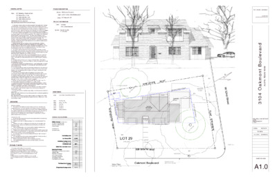
GENERAL NOTES PROJECT DESCRIPTION Address: 3104 Oakmont Boulevard Legal: Lot 29 - the West 24 feet Brykerwoods G Zoning: SF-3 Windsor Rd NP PROJECT INFORMATION Owner: Tom Terkel 3104 Oakmont Boulevard Architect: Donald Harris AIA 512.297.4206 Codes 2021 International Residential Code 2020 National Electric Code 2021 Uniform Plumbing Code 2021 Uniform Mechanical Code Visit link below for more information https://publicinput.com/2021TechnicalCodeChanges 1. It is the intent of these Contract Documents to establish a high quality level of material and workmanship, but not necessarily to note and call for every last item of work to be done. Any item not specifically covered but deemed necessary for satisfactory completion of the work shall be accomplished by the Contractor in a manner consistent with the quality of work without additional cost to the owner. All material and methods of installation shall be in accordance with industry standards and manufacturer's recommendations. 2. The Contractor shall be responsible for a thorough review of all drawings specifications and existing conditions prior to commencement of work. This includes but is not limited to site utilities and the structural scope of work. The failure of the Contractor to report discrepancies and seek modification or change prior to commencement of work shall be construed as full acceptance of the condition in question by the Contractor. The Contractor shall assume responsibility for all work depicted by the Contract Documents regardless of whether the Subcontractors agree as to whose jurisdiction certain areas of the scope of work are under. 3. It shall be assumed that the Contractor and the Subcontractors are sufficiently experienced to be considered qualified in their respective work responsibilities. The Contractor shall insure that the Owner receives acceptable workmanship common to the industry from all Subcontractors and material suppliers and is responsible for hiring qualified staff personnel and/ or Subcontractors as necessary. 4. The Contractor shall verify the location of all existing utilities so that the work may proceed safely and be coordinated among all Subcontractors and personnel involved. The Contractor shall notify the Owner and Designer in advance of any work required by public utility entities that will affect the cost of schedule of the work. 5. The contractor shall meet all safety requirements applicable in the city of Austin and maintain a safe working environment for all personnel and occupants during the entire project. The jobsite is to be kept orderly and as clean as possible during all construction activities. 6. This drawing set is provided to communicate only the basic design of the building. Structural design by others, all plumbing and Electrical shall also be design build and shall be coordinated by contractor. 7. Any errors and omissions or inconsistencies found in these drawings shall be brought to the Architects attention immediately. Do not proceed with work until all issues have been resolved in writing. 8. Do not scale the drawings, written dimensions take precedence over scale dimensions. 9. All new construction dimensions are drawn to the face of new studs as shown on the drawings. Any inconsistencies shall be brought to the Designer's attention prior to the commencement of work. 10. The Contractor shall verify all grades and grading requirements prior to the commencement of work. Grades shown are approximate, therefore all stairs and finish floor elevations shall be coordinated in the field. Note: Two consecutive steps shall constitute a stair, and stairs shall not exceed 7 3/4" rise or a 10" run per code. Mount one handrail per stair to continue the length of the run at 34" above the nosing typical. All stairs shall be built in conformance with all codes as applicable. 11. All 'clear' and 'minimum' dimensions shall be within 1/8" along it's full length. No adjustments shall be made without the Designer's prior written consent. 12. Locations of all partitions and doors shall be approved by the Designer or Owner in the field prior to construction. The Contractor shall notify the Designer or Owner of any conflicts or discrepancies in the location of new construction. 13. Larger scale drawings take precedence over small scale, details take precedence over all. Contractor shall notify the Designer of any discrepancies in writing prior to commencement of work. 14. The Contractor and Owner shall take responsibility to meet all code and manufacturer's requirements. It is the responsibility of the Builder to insure the project conforms to all codes applicable at the time of construction. Note: Manufacturers installation guidelines take precedence over diagrammatic details and drawings. Any inconsistencies shall be brought to the Owner's attention prior to the commencement of work. SITE NOTES EROSION CONTROL 1. The contractor shall install erosion/sedimentation controls and tree/natural area protective fencing prior to any site preparation work (clearing, grubbing or excavation). 2. The contractor is required to inspect the controls and fences at weekly intervals and after significant rainfall events to insure that they are functioning properly. The person(s) responsible for maintenance of controls and fences shall immediately make any necessary repairs to damaged areas. Silt accumulation at controls must be removed when the depth reaches six (6) inches. TREE PROTECTION 1. All trees and natural areas shown on plan to be preserved shall be protected during construction with temporary fencing. 2. Protective fences shall be erected according to City of Austin Standards for Tree Protection. 3. Protective fences shall be installed prior to the start of any site preparation work (clearing, grubbing or grading), and shall be maintained throughout all phases of the construction project. 4. Erosion and sedimentation control barriers shall be installed or maintained in a manner which does not result in soil build-up within tree drip lines. 5. Protective fences shall surround the trees or group of trees, and will be located at the outermost limit of branches (drip line) , for natural areas, protective fences shall follow the Limit of Construction line, in order to prevent the following: A. Soil compaction in the root zone area resulting from vehicular traffic or storage of equipment or materials; B. Root zone disturbances due to grade changes (greater than 6 inches cut or fill), or trenching not reviewed and authorized by the City Aborist; C. Wounds to exposed roots, trunk or limbs by mechanical equipment; D. Other activities detrimental to trees such as chemical storage, cement truck cleaning, and fires. VISITABILITY NOTES 1. At noted ground floor bathroom on plan provide: lateral two-inch by six-inch or larger nominal wood blocking installed flush with stud edges of bathroom walls. Centerline of the blocking must be 34 inches from and parallel to the interior floor level, except for the portion of the wall located directly behind the lavatory. 2. All light switches to be intalled at 48"aff to top of box, all wall outlets and receptacles must be installed minimum 15"aff to bottom of box. I I I N O T C U R T S N O C R O G N T T M R E P W E V E R Y R O T A L U G E R R O F T O N I ELECTRICAL EASEMENT OHL 20" H A C K B E R R Y OHL POWER POLE R E A R YA R D S E T B A C K 1 0 ' DRIVEWAY 407 sq ft 34 sq ft GARAGE 291 sq ft N 1 9 ° 2 9 ' 1 5 " E 9 4 . 4 1 ' HOUSE FFE 605.00' 1,304 sq ft PORCH 34 sq ft 120 sq ft 25' FRONT YARD SETBACK 604 1 5 ' S I D E Y A R D S E T B A C K 29.5" P E C A N 603 1 5 ' - 0 " 7 2 . 4 4 ' S 7 0 ° 4 6 ' 0 0 " E N W 3 2 n d S t r e e t OHL POWER POLE Building & Impervious Coverage 603 5 ' S I D E Y A R D S E T B A C K N 7 0 ° 3 2 ' 0 0 " W 5 6 . 6 8 ' 604 LOT 29 6,104 sq ft S28°56'04"W 96.02' 605 WATER METER Site Plan SCALE: 1/8" = 1'-0" Oakmont Boulevard ELEVATION DATUM 604.71' AT CUT ON CURB Page 1 SHEET INDEX A1.0 Cover Sheet / General Notes/ Site Plan A2.1 A2.2 A2.3 A3.0 A3.1 A4.0 First Floor Plan Second Floor Plan Roof Plan Elevations Elevations Building Sections ZONING CALCULATIONS Building Coverage (roofed areas) 1st Floor Conditioned Area 2nd Floor Conditioned Area Carport-Garage Covered Patios Covered Porches 3104 1302 1049 290 34 34 1660 415 120 18 Total Building Area: 2709 0 Lot Area per Plat: % Building Coverage on Lot: areas under 7' tall Conditioned Area: 6,104 27.2% 2351 Yielded Floor Area Ratio on Lot: 0.3999 Impervious Coverage Total Building Coverage on Lot (above) Driveway Area Sidewalks & Walkways pool coping/pool deck Uncovered Wood Decks Air Conditioner Pads Other Impervious Coverage Total Impervious Coverage: allowable 2213 2746.8 % Impervious Coverage on Lot: 36.3% Don Harris | Architect 512.297.4206 www.donharrisarchitect.com d r a v e l u o B t n o m k a O 4 0 1 3 3 0 7 8 7 S A X E T , I N T S U A FULL SCALE AS NOTED AT 22x34 HALF SCALE AT 11X17 JOB No. 2022-3104 REVISION 8.27.2022 SCHEMATIC SHEET NUMBER A1.0 7'-7" 17'-5 1/2" 21'-5" 71'-4" 3 A4.0 16'-5" 13'-1 1/2" 1'-10 1/2" 1'-5" 1 A4.0 8'-5 1/2" " 0 1 - ' 2 DECK LIVING ROOM 10' CEILING 2-0x2-0 2-0x2-0 2-0x2-0 2-0x2-0 STAIR LINEN PRIMARY BATH SHOWER 0 - 3 x 0 - 2 2-6x8-0 3-0x8-0 " 0 - ' 0 3 2 A4.0 D W UTILITY 0 - 8 x 6 - 2 0 - 8 x 0 - 3 PRIMARY BEDROOM 12'4"x13'8" 3-0x8-0 CLOSET P U 2-0x8-0 " 0 - ' 2 " 6 - ' 3 " 0 - ' 2 " 2 / 1 6 - ' 5 " 6 - ' 9 " 2 / 1 7 - ' 4 CLOSET 0 - 6 x 8 - 2 ENTRY 9'-0" 2-8x8-0 POWDER F E R PANTRY 3-0x8-0 COVERED PORCH 10' CEILING ISLAND KITCHEN 10' CEILING " 6 - ' 3 2-8x6-0 2-8x6-0 2-8x6-0 DW 2-6x5-0 2-6x5-0 2-6x5-0 3-0x5-0 3-0x5-0 1'-6" 6'-1" 11'-4 1/2" 9'-7" 12'-10 1/2" 5'-1/2" 5'-7" 2'-7" 16'-8 1/2" 5 1/2" 42'-9 1/2" 1 A4.0 71'-4" 3 A4.0 GARAGE 10' CEILING 5'-4 1/2" 7'-9 1/2" 7'-9 1/2" " 0 - ' 2 1 P U L L O R ' 8 x ' 9 " 0 - ' 6 1 3-0x8-0 MUDROOM BAR DINING ROOM 10' CEILING E N W I 0 - 5 x 0 - 3 0 - 5 x 0 - 3 0 - 5 x 0 - 3 " 0 - ' 4 " 2 / 1 5 - ' 0 3 2 A4.0 " 0 - ' 3 1 " 0 - ' 1 " 2 / 1 5 Proposed Floor Plan SCALE: 1/4" = 1'-0" PROJECT NORTH LEGEND DOOR NOTES WINDOW NOTES NEW WALL FULL HEIGHT 2x6 @ 16"O.C. WOOD FRAME NEW WALL FULL HEIGHT 2x4 @ 16"O.C. WOOD FRAME NEW WALL PARTIAL HEIGHT 1. COORDINATE HARDWARE REQUIREMENTS WITH DOOR MANUFACTURER. 2. REFER TO FLOOR PLANS FOR SIZES. WIDTH AND HEIGHT DIMENSIONS ARE TYPICALLY DOOR LEAF SIZE. COORDINATE FRAMING R.O. FOR ADJACENT DOOR AND WINDOW ASSEMBLIES TO ALIGN HEAD HEIGHT AS SHOWN OR NOTED ON THE DRAWINGS. 3. PROVIDE TEMPERED GLASS AT ALL DOORS WITH LIGHTS. 4. PROVIDE SMOKE AND FIRE GASKETS AND CLOSER AT ALL RATED DOOR ASSEMBLIES. 5. PROVIDE RATED DOOR ASSEMBLIES WHERE NOTED ON PLAN. 6. PROVIDE SILLS AND THRESHOLDS AT ALL EXTERIOR DOORS. PROVIDE WOOD THRESHOLDS AT INTERIOR DOORS TO MATCH WOOD FLOOR WHERE APPLICABLE. 7. ALL EXTERIOR DOORS SHALL BE INSTALLED USING WEATHERLAPPED ELASTOMERIC FLASHING AT THE HEAD AND JAMBS. 8. COORDINATE ALL DOORS AS REQUIRED TO ACCOMMODATE FLOOR FINISHES. 9. SUBMIT DOOR CUT SHEETS FOR OWNER APPROVAL PRIOR TO ORDERING. 10. PROVIDE WEATHERSTRIPPING AT ALL DOORS. ANY DAMAGED WEATHERSTRIPPING SHALL BE REMOVED AND REPLACED. 11. PROVIDE TEMPERED GLASS AT SHOWER STALLS AND BUILT IN FURNITURE WITH GLASS DOORS. ANDERSEN 100 SERIES WINDOWS 1. DOUBLE GLAZED, LOW-E W/ U-VALUE OF 0.50 OR LOWER AND SHGH .20 OR LOWER, AS APPROVED BY OWNER AND ARCHITECT 2. REFER TO PLANS FOR TYPE AND SIZES. DIMENSIONS SHOWN ARE FRAME SIZE. VERIFY ROUGH OPENINGS AND WINDOW SIZES WITH MANUFACTURER AND LOCATION. NOTIFY DESIGNER OF ANY NECESSARY ADJUSTMENTS IN ROUGH OPENING REQUIREMENTS PRIOR TO ANY MODIFICATIONS. COORDINATE ASSEMBLY REQUIREMENTS WITH FRAMING REQUIREMENTS. 3. COORDINATE PIECES OF WINDOW ASSEMBLIES TO PRODUCE A UNIFIED, WEATHER TIGHT UNIT. 4. ALL WINDOWS SHALL BE INSTALLED USING WEATHERLAPPED ELASTOMERIC FLASHING AT THE HEAD JAMB AND SILLS 5. PROVIDE TEMPERED GLASS AT ALL WINDOWS LOCATED WITHIN 18" OF A DOOR, WHERE THE BOTTOM EDGE OF THE WINDOW IS LESS THAN 18" FROM THE FLOOR, ADJACENT TO A SHOWER OR TUB LESS THAN 60" TO SILL. Don Harris | Architect 512.297.4206 www.donharrisarchitect.com d r a v e l u o B t n o m k a O 4 0 1 3 3 0 7 8 7 S A X E T , I N T S U A FULL SCALE AS NOTED AT 22x34 HALF SCALE AT 11X17 JOB No. 2022-3104 REVISION 8.27.2022 SCHEMATIC SHEET NUMBER A2.1 I I I N O T C U R T S N O C R O G N T T M R E P W E V E R Y R O T A L U G E R R O F T O N I 17'-5 1/2" 3 A4.0 16'-10 1/2" 3-0x6-0 3-0x6-0 3-0x6-0 " 0 - ' 2 " 6 - ' 3 " 8 - ' 1 2 " 2 / 1 0 1 ROOF BELOW 0 - 3 x 6 - 2 BATH 2 2 - 6 x 8 - 0 CLOSET 2-6x8-0 0 - 8 x 8 - 2 BEDROOM 2 12'4"x14'3" 2 A4.0 HVAC CLOSET 0 - 8 x 8 - 2 0 - 8 x 6 - 2 2-6x8-0 BEDROOM 3 13'10"x10'4" DEN 15'10"x15'4" " 2 / 1 - ' 6 1 ROOF BELOW " 2 - ' 7 2 0 - 8 x 0 - 6 CLOSET " 2 / 1 1 - ' 1 1 2 A4.0 3-0x5-0 3-0x5-0 3'-8 1/2" 7'-6 1/2" 3-0x5-0 3-0x5-0 3-0x5-0 10'-3 1/2" 3'-3" 3 A4.0 Second Floor SCALE: 1/4" = 1'-0" PROJECT NORTH 1 A4.0 8'-5 1/2" 3-0x5-0 0 - 5 x 6 - 2 STAIR 0 1 1 1 2 1 3 1 4 1 5 1 6 1 7 1 N D BATH 3 2-6x3-0 18'-0" 42'-9 1/2" 1 A4.0 Don Harris | Architect 512.297.4206 www.donharrisarchitect.com d r a v e l u o B t n o m k a O 4 0 1 3 3 0 7 8 7 S A X E T , I N T S U A FULL SCALE AS NOTED AT 22x34 HALF SCALE AT 11X17 JOB No. 2022-3104 REVISION 8.27.2022 SCHEMATIC SHEET NUMBER A2.2 I I I N O T C U R T S N O C R O G N T T M R E P W E V E R Y R O T A L U G E R R O F T O N I 2 A4.0 RIDGE RIDGE 2 A4.0 10' PL HEIGHT RIDGE 2 1 : 0 1 E K A R RIDGE 2 1 : 0 1 2 1 : 0 1 10' PL HEIGHT 7' PL HEIGHT 2 1 : 0 1 2 1 : 0 1 2 1 : 4 9' PL HEIGHT 7' PL HEIGHT 9' PL HEIGHT 7' PL HEIGHT 9' PL HEIGHT DORMER DORMER DORMER 1 A4.0 3 A4.0 I T H G E H L P ' 9 10:12 10:12 V A L L E Y I T H G E H L P ' 9 VALLEY RIDGE 2 1 : 0 1 2 1 : 0 1 RIDGE 9' PL HEIGHT 2 1 : 0 1 RIDGE 2 1 : 0 1 E K A R 9' PL HEIGHT 2 1 : 0 1 E K A R 10' PL HEIGHT E G D R I 2 1 : 0 1 2 1 : 4 3 A4.0 2 1 : 0 1 2 1 : 0 1 2 1 : 4 1 A4.0 Roof Plan SCALE: 1/4" = 1'-0" PROJECT NORTH Don Harris | Architect 512.297.4206 www.donharrisarchitect.com d r a v e l u o B t n o m k a O 4 0 1 3 3 0 7 8 7 S A X E T , I N T S U A FULL SCALE AS NOTED AT 22x34 HALF SCALE AT 11X17 JOB No. 2022-3104 REVISION 8.27.2022 SCHEMATIC SHEET NUMBER A2.3 I I I N O T C U R T S N O C R O G N T T M R E P W E V E R Y R O T A L U G E R R O F T O N I 1 A4.0 3 A4.0 BRICK COMPOSITION SHINGLE ROOF BOARD AND BATTEN SIDING East SCALE: 1/4" = 1'-0" 2 A4.0 3 A4.0 South SCALE: 1/4" = 1'-0" 1 A4.0 " 0 - ' 9 " 0 - ' 0 1 I I I N O T C U R T S N O C R O G N T T M R E P W E V E R Y R O T A L U G E R R O F T O N I North SCALE: 1/4" = 1'-0" West SCALE: 1/4" = 1'-0" 2 A4.0 Don Harris | Architect 512.297.4206 www.donharrisarchitect.com d r a v e l u o B t n o m k a O 4 0 1 3 3 0 7 8 7 S A X E T , I N T S U A FULL SCALE AS NOTED AT 22x34 HALF SCALE AT 11X17 JOB No. 2022-3104 REVISION 8.27.2022 SCHEMATIC SHEET NUMBER A3.0 3 A4.0 1 A4.0 West SCALE: 1/4" = 1'-0" 3 A4.0 1 A4.0 1 A4.0 2 A4.0 2 A4.0 1 A4.0 I I I N O T C U R T S N O C R O G N T T M R E P W E V E R Y R O T A L U G E R R O F T O N I " 0 - ' 7 " 0 - ' 8 BEDROOM " 0 - ' 3 STUDY STAIR " 0 - ' 8 " 6 - ' 0 1 " 0 - ' 9 PANTRY " 0 - ' 0 1 ENTRY PORCH PORCH " 0 - ' 0 1 1 Building Section SCALE: 1/4" = 1'-0" 1 A4.0 2 A4.0 2 Building Section SCALE: 1/4" = 1'-0" 2 A4.0 1 A4.0 Don Harris | Architect 512.297.4206 www.donharrisarchitect.com d r a v e l u o B t n o m k a O 4 0 1 3 3 0 7 8 7 S A X E T , I N T S U A FULL SCALE AS NOTED AT 22x34 HALF SCALE AT 11X17 JOB No. 2022-3104 REVISION 8.27.2022 SCHEMATIC SHEET NUMBER A3.1 1 A4.0 3 A4.0 " 0 - ' 9 HALL BATH STAIR BEDROOM CLOSET HALL DEN " 0 - ' 0 1 PORCH CLOSET BEDROOM ATTIC DINING ROOM STAIR 1 A4.0 LIVING ROOM 3 A4.0 1 Building Section SCALE: 1/4" = 1'-0" 2 Building Section SCALE: 1/4" = 1'-0" 2 A4.0 ENTRY 2 A4.0 2 A4.0 I I I N O T C U R T S N O C R O G N T T M R E P W E V E R Y R O T A L U G E R R O F T O N I BEDROOM DEN LIVING ROOM 3 Building Section SCALE: 1/4" = 1'-0" 2 A4.0 Don Harris | Architect 512.297.4206 www.donharrisarchitect.com d r a v e l u o B t n o m k a O 4 0 1 3 3 0 7 8 7 S A X E T , I N T S U A FULL SCALE AS NOTED AT 22x34 HALF SCALE AT 11X17 JOB No. 2022-3104 REVISION 8.27.2022 SCHEMATIC SHEET NUMBER A4.0