18.2 - 2607 McCallum - plans — original pdf
Backup
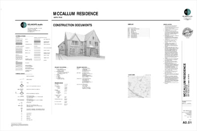
1 2 / 8 0 / 0 1 MCCALLUM RESIDENCE AUSTIN, TEXAS CONSTRUCTION DOCUMENTS BATT INSULATION COMPRESSIBLE JOINT FILLER RIGID INSULATION GYPSUM WALLBOARD CEMENT BOARD CEMENT STUCCO ON METAL LATH CARPET & PAD RUBBBER/VCT MARBLE 916 Springdale, Bldg 4 #104 Austin, TX 78702 bart@delineatestudio.com 512.522.3511 MATERIAL HATCHES SITEWORK THERMAL, MOISTURE PROTECTION CONCRETE, MASONRY FINISHES EARTH GRAVEL CRUSHED STONE CONCRETE BRUCK, U.N.O. BRICK, U.N.O. STEEL ALUMINUM & NON- FERROUS METALS PLYWOOD WOOD FRAMING - THROUGH MEMBER WOOD FRAMING - INTERRUPTED MEMBER FINISHED WOOD/ MILLWORK EXISTING CONTOUR NEW CONTOUR TREE METALS WOOD SYMBOLS LEGEND ELEVATION TAG (DRAWING #, SHEET #) SECTION TAG (DRAWING #, SHEET #) DETAIL TAG (DRAWING #, SHEET #) 100.00-TC 100.00-TC EXISTING ELEVATION TC= TOP OF CONCRETE, TG+ TOP OF GRADE TW= TOP OF WALL NEW ELEVATION TC= TOP OF CONCRETE, TG=TOP OF GRADE TW= TOP OF WALL KEYED NOTE WALL TYPE - SEE WALL DETAILS (SEE WALL SECTIONS FOR EXTERIOR WALL CONSTRUCTION) HORIZONTAL ASSEMBLY - SEE ASSEMBLY DETAILS (HORIZONTAL ASSEMBLIES NOTED ON SECTIONS) 1 A4.01 1 A5.01 1 A8.01 1 S2 S2 (R) (E) (D) CJ D.S. DOWNSPOUT RELOCATED EXISTING DEMOLISH CONTROL JOINT Notice of Copyright Protection: © Copyright 2021 This drawing and details on it are the sole property of the architect and may be used for this specific project only. It shall not be loaned, copied or reproduced, in whle or in part, or for any other purpose or project without written consent of the architect PROJECT DIRECTORY OWNER LAURA AND JOHN LEE (512) 368-0938 laura@lauraleehome.com jleecpa3@gmail.com ARCHITECT STRUCTURAL HOLLINGSWORTH PACK DELINEATE STUDIO BART WHATLEY, ARCHITECT (512) 522-3511 bart@delineatestudio.com 916 SPRINGDALE RD. #4-104 AUSTIN, TX 78702 CHRIS HEWITT, PE (512) 275-6060 X101 chris.h@holl-pack.com 3801 S CONGRESS AVE #110 AUSTIN, TX 78704 DAVID MORGAN (512) 778-5573 idmbuilders@gmail.com 350 COUNTY ROAD 258 LIBERTY HILL, TX 78642 LOT AREA 10131 SF CONTRACTOR IDM BUILDERS PROJECT DESCRIPTION 1. PROJECT ADDRESS: 2607 MCCALLUM DRIVE AUSTIN, TX 78703 2. LEGAL DESCRIPTION: S 55 FT OF LOT 22 *& N 15 FT OF LOT 24 BLK 17 PEMBERTON HEIGHTS SEC 8 3. ZONING: SF3-NP 4. LOT SIZE: 10232 SF 7. APPLICABLE CODES: 2021 IRC, 2021 IECC PROJECT AREAS MAIN HOUSE Conditioned Level 1 Level 2 GARAGE Conditioned Level 2 Unconditioned Level 1 COVERED PORCH Main House Front Back FAR (Gross Floor Area) BUILDING COVER IMPERVIOUS COVER 3442 SF 1786 SF 1656 SF 1054 SF 527 SF 527 SF 32 SF 18 SF 4046 SF 39.94% 2397 SF 23.66% 4377.5 SF 43.21% SHEET LIST Cover Sheet & Gen Notes A R C H I T E C T U R A L A0.01 A0.21 Window Types Site Demo Plan A0.91 Site Plan A1.01 Site Setback Plan A1.02 Tree Protection Site Plan A1.03 Level 1 Floor Plan A2.01 Level 2 Floor Plan A2.02 Building Elevations A4.01 Building Elevations A4.02 VICINITY MAP: SITE LOCATION GENERAL NOTES 1. Drawings are for permitting and do not address all elements of construction. Construction administration services by the architect should be contracted. 2. Contractor is responsible for protecting all completed work. 3. Contractor shall schedule and obtain permission from building owner for access to any building/site areas outside the limits of construction. Contractor responsible for protecting and cleaning any of these access areas. 4. All work shall be constructed in compliance with adopted codes, local amendments/rules, and state regulations. Contractor responsible for coordination of requirements. 5. Contractor shall verify and correlate all dimensions on the job site. Use dimensions indicated. Do not scale drawings. Immediately notify the architect of any discrepancies in the drawings, specifications, or actual job conditions which affect the execution of the work as intended. 6. 7. Contractor shall comply with the Texas statute governing trench safety. Any trench excavation exceeding 5 feet shall comply with Texas "occupational safety" and "health administration" standards. See structural/civil for any special shoring requirements. Geotechnical information may be included in the project manual or available from the architect. Contractor's pay request must contain a separate pay line for excavation safety systems. The above trench requirements are required by Texas law for both public and private projects. 8. Contractor shall supply all necessary labor and material necessary to complete the work described herein. 9. Fire extinguishers shall be provided in accordance with NFPA 10 and local fire department requirements. 10. Access panels shall be provided and installed where required by building code or for the proper operation or maintenance of mechanical/electrical equipment, whether or not indicated on the drawings. Contractor shall coordinate size, location, and type of access panel with work of all trades. All access panels shall receive approval of the architect. 11. Contractor shall perform any work within public right-of-way according to gov. agency requirements. 12. The contractor shall obtain and pay fees for all necessary permits, licenses, certificates, testing. 13. Furnish all new materials except where specifically noted otherwise. Warrant all materials and labor for a period of one year from the date of substantial completion, or the date of beneficial occupancy by the owner, whichever is later. Repair or replace all work that is discovered to be defective during that period. 14. The contractor shall coordinate the work of all trades. 6/14/2022 I E C N E D S E R M U L L A C C M 3 0 7 8 7 X T , n i t s u A , e v i r D m u l l a C c M 7 0 6 2 N O I T C U R T S N O C W E N REVISIONS NUMBER DATE DESCRIPTION Cover Sheet & Gen Notes CONSTRUCTION DOCUMENTS DATE: 6 /14 /2022 JOB: 2204 SHEET: A0.01 M P 1 3 : 5 5 : 3 2 2 0 2 1 2 6 / / 6' - 0" 6' - 0" 2' - 6" 3' - 0" 12' - 0" 8' - 0" 3' - 0" " 6 - ' 6 " 0 - ' 2 " 6 - ' 5 " 0 - ' 3 " 6 - ' 5 " 0 - ' 2 " 0 - ' 4 " 6 - ' 4 " 0 - ' 5 " 6 - ' 2 " 0 - ' 6 " 6 - ' 2 " 0 - ' 4 " 6 - ' 3 " 6 - ' 5 " 0 - ' 2 " 0 - ' 5 " 6 - ' 2 " 6 - ' 3 " 0 - ' 4 A W INDOW SINGLE HUNG B W INDOW SINGLE HUNG C W INDOW SINGLE HUNG BATH D W INDOW SINGLE HUNG E W INDOW SINGLE HUNG F W INDOW SINGLE HUNG 2' - 6" G W INDOW SINGLE HUNG 2' - 0" 2' - 0" 9' - 0" 3' - 0" 3' - 0" 6' - 0" 2' - 6" 2' - 6" 6' - 0" 4' - 0" 5' - 0" " 0 - ' 6 " 6 - ' 2 " 0 - ' 5 " 6 - ' 2 " 0 - ' 5 " 0 - ' 2 " 6 - ' 4 " 0 - ' 3 " 0 - ' 5 " 0 - ' 2 " 0 - ' 5 " 6 - ' 3 " 0 - ' 5 " 6 - ' 2 " 9 - ' 3 . S V E L E . T X E . F E R " 6 - ' 3 " 6 - ' 3 " 0 - ' 5 " 6 - ' 3 " 0 - ' 3 . S V E L E . T X E . F E R " 6 - ' 3 " 6 - ' 3 3' - 0" 9' - 0" 2' - 6" 2' - 10" S W INDOW SINGLE HUNG T W INDOW SINGLE HUNG U W INDOW SINGLE HUNG V W INDOW SINGLE HUNG H W INDOW SINGLE HUNG I W INDOW SINGLE HUNG J W INDOW SINGLE HUNG K W INDOW SINGLE HUNG L W INDOW SINGLE HUNG M W INDOW SINGLE HUNG BATH N W INDOW SINGLE HUNG O W INDOW SINGLE HUNG P W INDOW SINGLE HUNG BATHTUB Q W INDOW FIXED R W INDOW FIXED VISITABILITY NOTES: 6 /14 /2022 TRANSITION STRIP . X A M " 2 / 1 . X A M " 8 / 3 1 . X A M " 2 / 1 DOOR SEAL THRESHOLD . X A M " 2 / 1 INTERIOR EXTERIOR 2 VISITABLE ENTRY THRESHOLD 3" = 1'-0" 1. First floor to comply with all visitability standards under city code Sec. 25-12-243, R320. Visitability items are referenced on floor plans. 2. Visitable bathrooms (R320.3): At least 1 bathroom group must contain the following: A) Minimal net clear opening of 30"; B) Lateral 2x6 blocking, centerline 34" from finished floor, except for the portion behind the lavatory. C) 30”x30” floor space not impeded by door swing. D) Bath walls to have lateral 2x6 blocking, centerline 34" from finished floor, except for portion behind lavatory. 3. Visitable light switches, receptacles and environmental controls (R320.4): The first floor of a dwelling must contain the following: A) All light switches and environmental controls shall not be installed greater than 48" above the finished floor; B) All outlets and receptacles shall be installed no less than 18" above floor. This measurement is from the top of the device or box to the unfinished floor. 4. Visitable bathroom route (R320.5): All bathrooms designated for visitability on the first floor will be accessible by a route with a minimum clear pathway of 36" beginning at the visitable entrance and continuing through the living room, dining room, and kitchen. Any living space on a first floor requires a visitable bathroom, though living and kitchen is not required to be on the first floor. 5. Visitable dwelling entrance (R320.6): A dwelling must be accessible by at least one "no-step" entrance (Detail 2/BP-5) and the door shall have a net clear opening of 32" served by a 36” min. exterior route WINDOW NOTES 1. Glazing within 24” of either side of any door shall be tempered unless noted as wire glass. 2. Glazing greater than 9 S.F. in area with a bottom edge less than 18” above (and horizontally within 36”) or a walking surface shall be tempered. 3. Exterior glazing shall be tinted as selected by owner. 4. Minimum window specifications: see energy code compliance report. (See Owner/Architect for actual selection.) 5. At least one window in each bedroom shall be 44” A.F.F. max. and open 20” wide min. by 24” high min. and open 5.7 S.F. 6. For windows with sills less than 24” A.F.F. and where floors are 30” above exterior grade, window shall open no more than 4” or shall have an interior opening rail/guard that is operable at egress windows. 7. Exterior glazing shall be insulated. 8. Dimensions are nominal frame sizes, actual sizes vary by manufacturer. 9. Contractor responsible for verifying actual dimensions and rough openings. WINDOW LEGEND SEE COVER SHEET FOR COMPLETE SYMBOLS LEGEND REVISIONS DETAIL REFERENCE NUMBER DATE DESCRIPTION 1 A101 T TEMPERED I E C N E D S E R M U L L A C C M 3 0 7 8 7 X T , n i t s u A , e v i r D m u l l a C c M 7 0 6 2 N O I T C U R T S N O C W E N Window Types CONSTRUCTION DOCUMENTS DATE: 6 /14 /2022 JOB: 2204 SHEET: A0.21 Notice of Copyright Protection: © Copyright 2020 This drawing and details on it are the sole property of the architect and may be used for this specific project only. It shall not be loaned, copied or reproduced, in whole or in part, or for any other purpose or project without written consent of the architect 1 WINDOW TYPES 1/4" = 1'-0" M P 1 3 : 5 5 : 3 2 2 0 2 1 2 6 / / EXIST. DRIVE SHALL BE REMOVED FROM BACK TO FRONT, WITH EQUIPMENT ON CONC. PAVING TO PROTECT CRZS. (D) EDGING (D) DRIVE 10' x 100' BLDG LINE (DEED) 10" AM. ELM S 60° 02' 00" E 144.77' 18" AM. ELM (E) SITE WALL (D) SITE WALL 5' SETBACK PREVIOUS LOCATION OF 1-STORY GARAGE DEMO PERMIT 2020-144517 LOT 22 LOT AREA 10131 SF ' 8 9 . 9 6 E " 0 0 ' 0 0 ° 0 3 N 35" LIVE OAK K C A B T E S ' 5 2 ) D E E D ( I E N L G D L B ' 0 4 28" LIVE OAK (E) W (D) DRIVE (D) WALK 35" LIVE OAK (E) W 17" RED OAK PREVIOUS LOCATION OF 2- STORY RESIDENCE DEMO PERMIT 2020-144516 EXIST. DRIVES SHALL BE USED FOR STORAGE AND VEHICLE ACCESS FOR AS LONG AS POSSIBLE DURING CONSTRUCTION TO PROTECT CRZS. (E) CURB CUT I E V R D M U L L A C C M 7 0 6 2 . . W O R . ' 0 5 (E) WM AND LINE (D) CURB CUT. REPLACE W/ CURB & GUTTER (E) GAS LINE (E) WW C.O. AND LINE (E) G (E)WW (E) WW (E) WW (E) G 20" PECAN 18" CHINESE TALLOW LOT 24 18" LIGUSTRUM (MS 11" 8" 6") ADJACENT RESIDENCE 5' SETBACK N 60° 02' 00" W 144.77' Notice of Copyright Protection: © Copyright 2020 This drawing and details on it are the sole property of the architect and may be used for this specific project only. It shall not be loaned, copied or reproduced, in whole or in part, or for any other purpose or project without written consent of the architect 1 SITE DEMO PLAN 1/8" = 1'-0" GENERAL SITE DEMO NOTES: 1. Existing house and garage have been demolished under permits 2020-144516 & 2020-144517. 2. Coordinate all demolition activities with the appropriate trade, agency, utility company, etc., as required. 3. Protect all existing utility service lines, indicated or not, and repair and replace any damaged utility service lines. 4. Locate, identify, stub off, and disconnect utility services that are not indicated to remain. LEGEND STRUCTURE TO BE DEMO'D HARDSCAPE TO BE DEMO'D FULL CRZ 1/2 CRZ 1/4 CRZ CRITICAL ROOT ZONE OF PROTECTED TREE 6 /14 /2022 ABBREVIATIONS (E) EXISTING (R) RELOCATED (D) DEMOLISH CJ CONTROL JOINT CRZ CRITICAL ROOT ZONE CU CONDENSING UNIT EM ELEC METER OHE OVERHEAD ELEC UGE UNDERGROUND ELEC UP UTILITY POLE GM GAS METER WATER METER WM WW WASTE WATER IC D.S. IMPERVIOUS COVER DOWNSPOUT I E C N E D S E R M U L L A C C M 3 0 7 8 7 X T , n i t s u A , e v i r D m u l l a C c M 7 0 6 2 N O I T C U R T S N O C W E N REVISIONS NUMBER DATE DESCRIPTION Site Demo Plan CONSTRUCTION DOCUMENTS DATE: 6 /14 /2022 JOB: 2204 SHEET: A0.91 E H O E H O E H O K C A B T E S ' 0 1 . . E U P . ' 5 ' 8 9 . 9 6 W " 0 0 ' 0 0 ° 0 3 S 18" CHINESE TALLOW 18" CHINESE TALLOW (E) PULL BOX (E) UP M P 4 3 : 5 5 : 3 2 2 0 2 1 2 6 / / GENERAL SITE NOTES 1. Any work that involves cutting or damage to existing conditions shall be repaired to match existing. 2. Locate and mark all utilities prior to construction notify underground utility companies 48 hours prior to any excavation. Repair any damaged utility lines at contractor's expense. 3. Construction materials shall be delivered via path and site entrance determined in pre- construction meeting. 4. Coordinate with owner for special permits required for any temporary blockage of driveways, streets, or parking areas as required during construction. 5. Remove all existing construction and landscaping within the footprint of the new construction. 6. Contractor shall construct all new grades as indicated. Assume a constant slope between new relative spot elevations. 7. Slope grade away from new building a minimum of 4% for 6 feet. Slope new impervious surfaces away from building at 2% (1/4" per foot) for 6 feet minimum. 8. Provide a rough broom finish on all new exterior concrete walks. 9. Restore existing landscape areas and lawns damaged by construction with sod. 10. Provide reinforced HVAC unit, transformer, and generator pads as required by mechanical and electrical. Pad sizes shown are approximate sizes. Concrete pads shall be sized to accommodate manufacturer's recommendations. 11. The limits of construction shall include, but not be limited to 12 feet outside of any constructed or renovated area and not to extend beyond the property line. 12. Stockpiling of excavated or fill material shall be limited to an area as defined by the Architect / Owner. 13. Trim all trees within 4 feet of new building. Coordinate any tree removal or pruning with the city tree permit. Provide city required tree protection. 14. Indicated (100.0') finish floor elevation is a reference elevations. Actual finish floor elevation above sea level differs. All elevations are relative to F.F. (100.0') unless noted without parenthesis as 792.2' 15. Site information provided by owner. Architect is not responsible for inaccurate site information or problems caused by inaccurate site information. 16. Provide one pre-cast concrete splash block at each downspout extending 4 feet from building, unless downspout is tied into storm drain or drains on to concrete surface. SITE LEGEND 6 /14 /2022 I E V R D M U L L A C C M 7 0 6 2 . . W O R . ' 0 5 UPGRADE WM IN EXIST. LOCATION SIDEWALK FEE- IN-LIEU HAS BEEN PAID (E) WW CO OVERHANG, FLOOR ABOVE 7 SF 593.33' HIGH GRADE FENCES AND GATES TO COMPLY WITH IRC 305 (E) RETAINING WALL REMAINS EM 593.9' HIGH GRADE E H O 594.00' EXIST. GRADE 594' LOT 22 594.50' 593.60' EXIST. GRADE LOT AREA 10131 SF K C A B T E S ' 5 2 ' 8 9 . 9 6 E " 0 0 ' 0 0 ° 0 3 N 35" LIVE OAK 28" LIVE OAK ) D E E D ( E N I L G D L B ' 0 4 593.75' 10' x 100' BLDG LINE (DEED) " 1 1 - ' 3 1 FLAT SLOPE CONC. DRIVE 1036 SF 593.75' 5' SETBACK 593.50' 594.60' 593.30' EXIST. GRADE 10" AM. ELM S 60° 02' 00" E 144.77' 593.30' EXIST. GRADE 18" AM. ELM 593.90' EXIST. GRADE SLOPE 594.50' " 2 - ' 5 CU 9 SF 2-STORY GARAGE / ADU WOOD FRAMED, SLAB ON GRADE LEVEL 1 LEVEL 2 527 SF 527 SF T.O.SLAB AVG GRADE 593.00' (99'-0") 594.50' (100'-6") SWALE 11' - 3" E G U E H O 7' - 11" EAVE TO OHE SIDEWALK 12 SF COVERED PORCH 18 SF OVERHANG, FLOOR ABOVE 2 SF STEPS 9 SF 594.00' VISITABLE ROUTE 593.50' 593.96' 593.25' 593.00' DRAIN 593.83' SLOPE 593.50' SIDEWALK 9 SF UP " 0 - ' 0 7 35" LIVE OAK (E) W 592' (E) W 17" RED OAK 592.00' 593.75' 2 STORY RESIDENCE WOOD FRAMED, PIER AND BEAM t r o a r e g i r f e R LEVEL 1 LEVEL 2 1786 SF 1656 SF PATIO 281 SF 19' - 6" 593.75' 593.25' WD DECK 483 SF T.O.DECKING AVG GRADE 594.00' (100'-0") 591.66' (97'-8") SLOPE 590.50' (E) G (E) WW 590' (E) G (E) WW 18" CHINESE TALLOW LOT 24 20" PECAN FENCE AND GATE TO COMPLY WITH IRC 305 ROOF OVERHANG 590.0' LOW GRADE POOL COPING 80 SF COVERED PORCH 57 SF STEPS 30 SF SIDEWALK 148 SF GM " 1 - ' 9 CU 9 SF CU 9 SF 18" LIGUSTRUM (MS 11" 8" 6") ADJACENT RESIDENCE POOL 20' - 0" 14' - 0" 1' - 2" DAYLIGHT UNDER DECK 593.75' 593.25' 5' SETBACK SWALE OR LEVEL SPREADER N 60° 02' 00" W 144.77' 588' 1 SITE PLAN 1/8" = 1'-0" 594.00' 593' 592' 593.25' TOP OF COPING 591' 22' - 3" K C A B T E S ' 0 1 590' " 4 - ' 4 " 3 - ' 3 1 " 0 - ' 2 1 " 1 - ' 3 1 ROOF OVERHANG (2) CAR PARKS 17'-6" X 8'-6" 592.1' LOW GRADE POOL EQUIP. 18 SF SIDEWALK/ STEPS 36 SF ' 8 9 . 9 6 W " 0 0 ' 0 0 ° 0 3 S . . E U P . ' 5 E G U 18" CHINESE TALLOW 18" CHINESE TALLOW (E) PULL BOX (E) UP E H O EXISTING CONTOUR NEW CONTOUR FENCE BUILDING ENTRANCE 100'-0" SPOT ELEVATION NEW STRUCTURE IMPERVIOUS COVER PORTION OF CANTILEVERED SLAB OVER 1/2 CRZ FULL CRZ 1/2 CRZ 1/4 CRZ I E C N E D S E R M U L L A C C M 3 0 7 8 7 X T , n i t s u A , e v i r D m u l l a C c M 7 0 6 2 N O I T C U R T S N O C W E N CRITICAL ROOT ZONE OF PROTECTED TREE REVISIONS NUMBER DATE DESCRIPTION ABBREVIATIONS EXISTING (E) RELOCATED (R) DEMOLISH (D) CONTROL JOINT CJ CRITICAL ROOT ZONE CRZ CONDENSING UNIT CU ELEC METER EM OVERHEAD ELEC OHE UNDERGROUND ELEC UGE UTILITY POLE UP GAS METER GM WATER METER WM WW WASTE WATER IC D.S. IMPERVIOUS COVER DOWNSPOUT Site Plan CONSTRUCTION DOCUMENTS DATE: 6 /14 /2022 JOB: 2204 SHEET: A1.01 Notice of Copyright Protection: © Copyright 2020 This drawing and details on it are the sole property of the architect and may be used for this specific project only. It shall not be loaned, copied or reproduced, in whole or in part, or for any other purpose or project without written consent of the architect M P 8 3 : 5 5 : 3 2 2 0 2 1 2 6 / / 5 9 4 0 . ' 594' LOT 22 5 9 4 5 . ' 5 9 4 6 . ' 10" AM. ELM S 60° 02' 00" E 144.77' 5 9 3 3 . ' HIGH GRADE PORTIONS 1 & 2 5' SETBACK 593.33' HIGH GRADE 10'x100' SETBACK (DEED) HIGH GRADE PORTION 3 18" AM. ELM 5 9 3 9 . ' 593.9' HIGH GRADE 2-STORY GARAGE / ADU LEVEL 1 LEVEL 2 527 SF 527 SF T.O.SLAB AVG GRADE 593.00' (99'-0") 594.50' (100'-6") UP 592.1' LOW GRADE 28" LIVE OAK ) D E E D ( E N I L G D L B ' 0 4 592' 17" RED OAK K C A B T E S ' 5 2 590' r o a 2 STORY RESIDENCE r e g WOOD FRAMED i r f e R t PORCH OVERHANG LEVEL 1 LEVEL 2 1786 SF 1656 SF T.O.SLAB AVG GRADE 594.00' (100'-0") 591.66' (97'-8") 20" PECAN 5 9 0 . 4 ' 18" LIGUSTRUM (MS 11" 8" 6") 5 9 0 . 1 ' 5 8 9 . 3 ' 5' SETBACK 590.0' LOW GRADE N 60° 02' 00" W 144.77' LOT 24 39' - 4" 40' - 0" PORTION 1 40' - 0" PORTION 2 25' - 8" PORTION 3 588' K C A B T E S ' 0 1 . . E U P . ' 5 ' 8 9 . 9 6 W " 0 0 ' 0 0 ° 0 3 S 18" CHINESE TALLOW 18" CHINESE TALLOW 5 8 8 . 7 ' E H O I E V R D M U L L A C C M 7 0 6 2 . . W O R . ' 0 5 35" LIVE OAK 35" LIVE OAK ' 8 9 . 9 6 E " 0 0 ' 0 0 ° 0 3 N 5 9 0 . 6 ' 18" CHINESE TALLOW Notice of Copyright Protection: © Copyright 2020 This drawing and details on it are the sole property of the architect and may be used for this specific project only. It shall not be loaned, copied or reproduced, in whole or in part, or for any other purpose or project without written consent of the architect 1 3D SETBACK TENT 1/8" = 1'-0" 6 /14 /2022 I E C N E D S E R M U L L A C C M 3 0 7 8 7 X T , n i t s u A , e v i r D m u l l a C c M 7 0 6 2 N O I T C U R T S N O C W E N REVISIONS NUMBER DATE DESCRIPTION Site Setback Plan CONSTRUCTION DOCUMENTS DATE: 6 /14 /2022 JOB: 2204 SHEET: A1.02 M P 0 4 : 5 5 : 3 2 2 0 2 1 2 6 / / 3 TREE PROTECTION DETAILS (E) DRIVE (E) DRIVE. REF. A0.91 FOR ADDITIONAL NOTES. I E V I R E V D R M D M U U L L L L A A C C C M C 7 M 0 6 7 2 0 6 2 . . . . W W O O R R . . ' 0 5 ' 0 5 MATERIAL STAGING TOILET CONSTRUCTION DUMPSTER NEW PAVED DRIVEWAY SHALL BE PLACED WITHIN THE FOOTPRINT OF EXISTING. NO ADDITIONAL EXCAVATION OR COMPACTION SHALL OCCUR WITHIN THE ½ CRZ OF ANY PROTECTED TREE. 35" LIVE OAK 9 " - R 8 ' R 17' - 6" 35" LIVE OAK R 8 ' - 9 " R 1 7 ' - 6 " R 35' - 0" R 35' - 0" R 7' - 0 " R 14' - 0" R 28' - 0" 28" LIVE OAK ) D E E D ( E N I L G D L B ' 0 4 17" RED OAK COVERED PORCH ' 8 9 . 9 6 E " 0 0 ' 0 0 ° 0 3 N 18" CHINESE TALLOW K C A B T E S ' 5 2 R 5 ' - 0 " 20" PECAN R 20' - 0" R 1 0' - 0" 10" AM. ELM S 60° 02' 00" E 144.77' 5' SETBACK 10' x 100' SETBACK (DEED) 2-STORY GARAGE / ADU LEVEL 1 LEVEL 2 527 SF 527 SF T.O.SLAB AVG GRADE 593.00' (99'-0") 594.50' (100'-6") E H O 18" AM. ELM E G U E H O r o a 2 STORY RESIDENCE r e g WOOD FRAMED i r f e R t LEVEL 1 LEVEL 2 1786 SF 1656 SF T.O.SLAB AVG GRADE 594.00' (100'-0") 591.66' (97'-8") 5' SETBACK N 60° 02' 00" W 144.77' 18" LIGUSTRUM (MS 11" 8" 6") K C A B T E S ' 0 1 . . E U ' P 5 . E G U ' 8 9 . 9 6 W " 0 0 ' 0 0 ° 0 3 S 18" CHINESE TALLOW 18" CHINESE TALLOW H O E 2 TREE PROTECTION DETAILS Notice of Copyright Protection: © Copyright 2020 This drawing and details on it are the sole property of the architect and may be used for this specific project only. It shall not be loaned, copied or reproduced, in whole or in part, or for any other purpose or project without written consent of the architect 1 TREE PROTECTION SITE PLAN 1/8" = 1'-0" TREE NOTES: 1. Avoid utility routes or meters within the 1/2 CRZ of protected trees. If trenching within the 1/2 CRZ cannot be avoided, the trenches must be air-spaded by a qualified arborist. 2. There shall be no access routes, material staging, concrete washouts, dumpsters, scaffolding, or portable toilets within the 1/2 CRZ of protected trees on the site. No more than 50% of the CRZ may be impacted by structures, staging, dumpsters. 3. Tree protection fencing (5' tall chain link) is required around all protected CRZs. When fencing cannot be installed around the full CRZ throughout construction, place the fencing at the 1/2 CRZ, and 8" layer of mulch from the 1/2 CRZ to the full CRZ. When fencing cannot be installed around the 1/2 CRZ throughout construction, 2x4x6 or greater lumber shall be strapped vertically to the tree and 8" of hardwood mulch shall be applied within the full CRZ. 4. All condensing unit pads to be placed on grade, no excavation within 1/2 CRZ. 5. Natural grade elevations to be preserved at all CRZs of protected trees. 6. No formwork will be installed within the 1/4 CRZ of a protected tree. 1. New paved driveway shall be placed within the footprint of the existing, paved driveway, and no additional excavation or compaction shall occur within the ½ CRZ of any protected tree. 2. No formwork will be will be installed within the 1/4 CRZ of a protected tree. LEGEND NEW STRUCTURE 8" LAYER OF MULCH FULL CRZ 1/2 CRZ 1/4 CRZ CRITICAL ROOT ZONE OF PROTECTED TREE TREE PROTECTION FENCING (SEE DETAILS ABOVE) 2x4 PLANKS, 6' TALL MIN. STRAPPED TO TREE TRUNK 6 /14 /2022 I E C N E D S E R M U L L A C C M 3 0 7 8 7 X T , n i t s u A , e v i r D m u l l a C c M 7 0 6 2 N O I T C U R T S N O C W E N REVISIONS NUMBER DATE DESCRIPTION Tree Protection Site Plan CONSTRUCTION DOCUMENTS DATE: 6 /14 /2022 JOB: 2204 SHEET: A1.03 M P 4 4 : 5 5 : 3 2 2 0 2 1 2 6 / / " 1 1 - ' 3 1 " 1 - ' 3 2 " 0 1 - ' 3 2 " 1 - ' 9 " 9 " 0 - ' 0 1 " 1 - ' 3 1 PROPERTY LINE FENCE AND GATE TO COMPLY WITH IRC 305 5' SETBACK EM 23' - 11" CU 11' - 5" " 2 - ' 5 " 0 1 - ' 1 2 ROOF OVERHANG SITE WALL STUCCO ON CMU TRELLIS ABOVE FENCE AND GATE TO COMPLY WITH IRC 305 4' - 8" 6' - 4" 27' - 0" 9' - 4" 1 A6.01 G G G 10' X 100' BLDG LINE (DEED) EXTERIOR VISITABLE ROUTE (2% SLOPE) VISITABLE ENTRANCE 36" WIDE DOOR. BEVELED THRESHOLD 1/2" MAX. COMPLY WITH CITY CODE SEC. 25-12-243 R320.6 CONC. DRIVE GARAGE 110 28" LIVE OAK ) D E E D ( I E N L G D L B ' 0 4 OFFICE 103 DINING 102 A A G COVERED PORCH 3'0 X 4'0" DOOR TO UNDER-STAIR STORAGE A CO SD UP 18 R @ 0' - 7 3/8" ENTRY 101 SD DEN 108 15" UPPERS Range KITCHEN 105 BBQ F PANTRY 104 t r o a r e g i r f e R 32" CLR. VISITIBALE ROUTE DOOR EQUIPPED WITH WATER HAZARD ENTRY ALARM TO COMPLY WITH IRC 305 14' - 0" POWDER 107 30" x 30" CLR FAMILY 106 HEARTH EXTENSION TO COMPLY WITH IRC 1001.1 E OUTDOOR LIVING POOL GM CU CU B C D D FENCE AND GATE TO COMPLY WITH IRC 305 VISITABLE BATHROOM 32" DOOR, 2X6 BLOCKING, C.L. AT 34" A.F.F. (EXCEPT BEHIND LAVATORY) WINDOWS EQUIPPED WITH WATER HAZARD ENTRY ALARM TO COMPLY WITH IRC 305 5' SETBACK PROPERTY LINE UP GRAVEL BELOW POOL EQUIP OUTDOOR DINING WOOD DECK DOOR EQUIPPED WITH WATER HAZARD ENTRY ALARM TO COMPLY WITH IRC 305 K C A B T E S ' 0 1 PLAN LEGEND 101101 1t E PT-1 HB EXISTING WALL NEW WALL DOOR IDENTITY - SEE DOOR SCHEDULE WINDOW IDENTITY - SEE WINDOW TYPES FINISH - SEE FINISH SCHEDULE HOSE BIBB (FROST FREE) 1-HR FIRE WALL SINGLE RECEPTACLE DUPLEX RECEPTACLE CLG GFI DUPLEX CEILING RECEPTACLE DUPLEX FLOOR RECEPTACLE GFI DUPLEX RECEPTACLE TRIPLE RECEPTACLE QUAD RECEPTACLE TELEPHONE/DATA COMBO OUTLET TELEPHONE OUTLET TELEVISION/CABLE JACK TV T FE GD G W THERMOSTAT ELECTRICAL PANEL FIRE EXTINGUISHER TYPE 2A10BC GARBAGE DISPOSAL GAS WATER Notice of Copyright Protection: © Copyright 2020 This drawing and details on it are the sole property of the architect and may be used for this specific project only. It shall not be loaned, copied or reproduced, in whole or in part, or for any other purpose or project without written consent of the architect 1 LEVEL 1 FLOOR PLAN 1/4" = 1'-0" 6 /14 /2022 I E C N E D S E R M U L L A C C M 3 0 7 8 7 X T , n i t s u A , e v i r D m u l l a C c M 7 0 6 2 N O I T C U R T S N O C W E N REVISIONS NUMBER DATE DESCRIPTION Level 1 Floor Plan CONSTRUCTION DOCUMENTS DATE: 6 /14 /2022 JOB: 2204 SHEET: A2.01 M P 5 4 : 5 5 : 3 2 2 0 2 1 2 6 / / " 1 1 - ' 2 " 0 - ' 2 1 " 2 - ' 8 J K " 1 - ' 3 2 " 0 1 - ' 3 2 6' - 4" 27' - 0" 9' - 4" 7" 7" L L M KNEE SPACE RECESSED MEDICINE CABINET 8" LEDGE NICHE M K RECESSED MEDICINE CABINET 22 X 54 ATTIC ACCESS HVAC W Steam BATH 2 201A BEDROOM 2 201 H MAIN BEDROOM 203 MAIN BATHROOM 203B P I SD MAIN CLOSET 203A LEVEL 2 HVAC ABOVE I HIS OFFICE O 204 CLOSET 1 202B HVAC CO SD LAUNDRY 205 DN SD BEDROOM 1 202 L L M N BATH 2 202A SD RECESSED MEDICINE CABINET L LEVEL 2 HVAC ABOVE S S RIDGE OF CATHEDRAL CEILING ABOVE " 0 1 - ' 1 2 " 1 - ' 4 23' - 11" V V DW MW 13' - 6" 9' - 6" APARTMENT 206 BATH 206A U T 18 R @ 0' - 7 1/16" DN LANDING 1X6 LEVEL DECK BOARDS TAPERED PT SLEEPERS DECKING ON SLOPED JOISTS, REF. STR. Notice of Copyright Protection: © Copyright 2020 This drawing and details on it are the sole property of the architect and may be used for this specific project only. It shall not be loaned, copied or reproduced, in whole or in part, or for any other purpose or project without written consent of the architect 1 LEVEL 2 FLOOR PLAN 1/4" = 1'-0" 0' 4' END OF FLAT CEILING ABOVE 22 X 30 ATTIC ACCESS HVAC ABOVE PAINTED STEEL RAIL PLAN LEGEND EXISTING WALL NEW WALL DOOR IDENTITY - SEE DOOR SCHEDULE WINDOW IDENTITY - SEE WINDOW TYPES FINISH - SEE FINISH SCHEDULE HOSE BIBB (FROST FREE) 1-HR FIRE WALL SINGLE RECEPTACLE DUPLEX RECEPTACLE CLG GFI DUPLEX CEILING RECEPTACLE DUPLEX FLOOR RECEPTACLE GFI DUPLEX RECEPTACLE TRIPLE RECEPTACLE QUAD RECEPTACLE TELEPHONE/DATA COMBO OUTLET TELEPHONE OUTLET TELEVISION/CABLE JACK THERMOSTAT FIRE EXTINGUISHER TYPE 2A10BC GARBAGE DISPOSAL GAS WATER 101101 1t E PT-1 HB TV T FE GD G W 6 /14 /2022 I E C N E D S E R M U L L A C C M 3 0 7 8 7 X T , n i t s u A , e v i r D m u l l a C c M 7 0 6 2 N O I T C U R T S N O C W E N Level 2 Floor Plan CONSTRUCTION DOCUMENTS DATE: 6 /14 /2022 JOB: 2204 SHEET: A2.02 ELECTRICAL PANEL REVISIONS NUMBER DATE DESCRIPTION M P 6 4 : 5 5 : 3 2 2 0 2 1 2 6 / / G N A H R E V O " 4 - ' 1 ) I G N M A R F M O R F ( ) D E E D ( E N I L G D L B ' 0 4 2 1 : 6 1 2 1 : 6 1 2 1 : 6 1 2 1 : 6 1 12:12 12:12 2 1 : 6 1 2 1 : 6 1 586 SF SOLAR READY ORIENTED 210° SOLAR READY NOTES 1. 2. 3. 4. Areas of roof covered by tree canopies more than 50% of annual daylight hours are exempt from solar ready, as are dwelling units less than 800 sf. The total solar area may be comprised of 1 or 2 zones, both having orientation between 300 deg clockwise to 90 deg of true north. Total solar ready zones shall not be less than 240 sf, with one at least 100 sf. No solar ready zones are to be less than 6'-0" on a side. Areas designated as solar ready are to be free and clear of any and all roof penetrations or obstructions. ADU EXEMPT ROOF AREA < 800 SF 335 SF SOLAR READY ORIENTED 210° E G U E H O S 60° 02' 00" E 144.77' 5' SETBACK 1' - 4" OVERHANG (FROM FRAMING) 60.00° 2 1 : 2 1 2 1 : 2 1 90.00° ' 8 9 . 9 6 W " 0 0 ' 0 0 ° 0 3 S K C A B T E S ' 0 1 . . E U P . ' 5 E G U 6 /14 /2022 I E C N E D S E R M U L L A C C M 3 0 7 8 7 X T , n i t s u A , e v i r D m u l l a C c M 7 0 6 2 N O I T C U R T S N O C W E N REVISIONS NUMBER DATE DESCRIPTION Roof Plan - Solar CONSTRUCTION DOCUMENTS DATE: 6 /14 /2022 JOB: 2204 SHEET: A2.03 5' SETBACK N 60° 02' 00" W 144.77' Notice of Copyright Protection: © Copyright 2020 This drawing and details on it are the sole property of the architect and may be used for this specific project only. It shall not be loaned, copied or reproduced, in whole or in part, or for any other purpose or project without written consent of the architect 1 ROOF PLAN - SOLAR READY 1/4" = 1'-0" M P 2 5 : 5 5 : 3 2 2 0 2 1 2 6 / / GARAGE LEVEL 2 - PLATE 119' - 3" GARAGE LEVEL 2 - F.F.E. 110' - 8" GARAGE LEVEL 1 - PLATE 109' - 1" GARAGE T.O.S (594.50') 100' - 6" AVG. GRADE GARAGE (593.00') 99' - 0" I I T H G E H G N D L I U B " 1 - ' 5 2 " 7 - ' 8 " 7 - ' 1 " 7 - ' 8 PORTION 3 - HIGH GRADE 593.9' SHINGLES STUCCO PAINTED STEEL TRELLIS " 0 - ' 5 1 PORTION 3 HIGH GRADE 593.9' " 0 - ' 5 1 R 110 V V 11" M L L I 11" R 9' - 5" GABLE PROTRUSION 12 12 E N I L G N D L I U B I LEVEL 2 - TOP PLATE 120' - 9" 6 /14 /2022 G G G G 2 NORTH ELEVATION 3/16" = 1'-0" PORTIONS 1 & 2 HIGH GRADE 594.6' I I T H G E H G N D L I U B " 7 - ' 0 3 " 1 - ' 9 " 7 - ' 1 " 1 - ' 0 1 LEVEL 2 - T.O.S. 111' - 8" LEVEL 1 - TOP PLATE 110' - 1" LEVEL 1 - T.O.S. (594.00') 100' - 0" AVG. GRADE (592.66') 97' - 8" 12 12 SHINGLES STUCCO S S 1' - 3" PAINTED STEEL RAIL H I J 12 16 Q 12 16 A A APARTMENT LANDING 1X6 DECK BOARDS, W/ 1/8" GAPS, ON FRAMING, REF. STR. GARAGE LEVEL 2 - PLATE 119' - 3" GARAGE LEVEL 2 - F.F.E. 110' - 8" GARAGE LEVEL 1 - PLATE 109' - 1" STEEL STAIR SITE WALL STUCCO ON CMU GARAGE T.O.S (594.50') 100' - 6" AVG. GRADE GARAGE (593.00') 99' - 0" I T H G E H G N D L I U B I " 6 - ' 5 2 " 7 - ' 8 " 7 - ' 1 " 7 - ' 8 " 8 Notice of Copyright Protection: © Copyright 2020 This drawing and details on it are the sole property of the architect and may be used for this specific project only. It shall not be loaned, copied or reproduced, in whole or in part, or for any other purpose or project without written consent of the architect 3 GARAGE WEST ELEVATION 3/16" = 1'-0" 1 WEST ELEVATION 3/16" = 1'-0" I E C N E D S E R M U L L A C C M 3 0 7 8 7 X T , n i t s u A , e v i r D m u l l a C c M 7 0 6 2 N O I T C U R T S N O C W E N Building Elevations CONSTRUCTION DOCUMENTS DATE: 6 /14 /2022 JOB: 2204 SHEET: A4.01 K A LEVEL 2 - TOP PLATE 120' - 9" LEVEL 1 - T.O.S. (594.00') 100' - 0" AVG. GRADE (592.66') 97' - 8" PORTIONS 1 & 2 HIGH GRADE 594.6' BRICK METAL ROOF " 0 - ' 5 1 9' - 1" I I T H G E H G N D L I U B " 7 - ' 0 3 " 1 - ' 9 " 7 - ' 1 " 1 - ' 0 1 ALL DOOR GLASS TO BE TEMPERED LEVEL 2 - T.O.S. 111' - 8" LEVEL 1 - TOP PLATE 110' - 1" REVISIONS NUMBER DATE DESCRIPTION M P 8 5 : 5 5 : 3 2 2 0 2 1 2 6 / / METAL CHIMNEY CAP " 0 - ' 2 Q METAL CHIMNEY CAP SHINGLES 8' - 8" GABLE PROTUSION 12 12 PTD. STEEL RAIL GARAGE LEVEL 2 - PLATE 119' - 3" I T H G E H G N D L I U B I " 6 - ' 5 2 " 7 - ' 8 " 7 - ' 1 " 7 - ' 8 GARAGE LEVEL 2 - F.F.E. 110' - 8" GARAGE LEVEL 1 - PLATE 109' - 1" " 0 - ' 5 1 STUCCO GARAGE T.O.S (594.50') 100' - 6" AVG. GRADE GARAGE (593.00') 99' - 0" PORTION 3 HIGH GRADE 593.9' K M O P E F 3 GARAGE EAST ELEVATION 3/16" = 1'-0" 2 EAST ELEVATION 3/16" = 1'-0" E N I L G N D L I U B I LEVEL 2 - TOP PLATE 120' - 9" METAL ROOF LEVEL 2 - T.O.S. 111' - 8" LEVEL 1 - TOP PLATE 110' - 1" I T H G E H G N D L I U B I " 7 - ' 0 3 " 1 - ' 9 " 7 - ' 1 " 3 - ' 0 1 LEVEL 1 - T.O.S. (594.00') 100' - 0" AVG. GRADE (592.66') 97' - 8" L L L N BRICK T U STUCCO M C B D D PAINTED STEEL RAILING PAINTED STEEL TRELLIS PAINTED STEEL GATE SITE WALL STUCCO ON CMU 206 110A Notice of Copyright Protection: © Copyright 2020 This drawing and details on it are the sole property of the architect and may be used for this specific project only. It shall not be loaned, copied or reproduced, in whole or in part, or for any other purpose or project without written consent of the architect PORTIONS 1 & 2 HIGH GRADE 594.6' 1 SOUTH ELEVATION 3/16" = 1'-0" SHINGLES BRICK METAL ROOF I T H G E H G N D L I U B I " 7 - ' 0 3 " 1 - ' 9 " 7 - ' 1 " 1 - ' 0 1 SITE WALL STUCCO ON CMU ALL DOOR GLASS TO BE TEMPERED PORTIONS 1 & 2 HIGH GRADE 594.6' LEVEL 1 - T.O.S. (594.00') 100' - 0" AVG. GRADE (592.66') 97' - 8" LEVEL 2 - TOP PLATE 120' - 9" LEVEL 2 - T.O.S. 111' - 8" LEVEL 1 - TOP PLATE 110' - 1" 6 /14 /2022 I E C N E D S E R M U L L A C C M 3 0 7 8 7 X T , n i t s u A , e v i r D m u l l a C c M 7 0 6 2 N O I T C U R T S N O C W E N SHINGLES I T H G E H G N D L I U B I " 6 - ' 5 2 " 7 - ' 8 " 7 - ' 1 " 7 - ' 8 STEEL STAIR " 0 - ' 5 1 GARAGE LEVEL 2 - PLATE 119' - 3" GARAGE LEVEL 2 - F.F.E. 110' - 8" GARAGE LEVEL 1 - PLATE 109' - 1" REVISIONS NUMBER DATE DESCRIPTION GARAGE T.O.S (594.50') 100' - 6" AVG. GRADE GARAGE (593.00') 99' - 0" ALL DOOR GLASS TO BE TEMPERED PORTION 3 HIGH GRADE 593.9' Building Elevations CONSTRUCTION DOCUMENTS DATE: 6 /14 /2022 JOB: 2204 SHEET: A4.02