B.6.1 - 1805 E. 3rd Street - Plans — original pdf
Backup
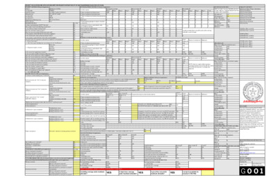
0 0 0 0 0 0 0 0 0 0 0 0 0 0 0 0 0 0 0 0 0 0 0 0 Maximum ADU area 953.7 ADU allowed? ADU proposed? Project ADU area Difference ADU L2 area Max ADU L2 area Difference Yes No 0 -953.7 0 550 -550 Total Remodeled Floor Area (SF) (work within existing habitable square footage) G002 General Notes G003 Standard Details G004 Standard Details G005 Standard Details G006 Environmental Details G007 Door Schedules G008 Window Schedules A000 Site Plan A101 Floor Plans, Level 01 A102 Floor Plans, Level 02 A104 Roof Plans A105 MEP Plans, Level 01 A106 MEP Plans, Level 02 A201 Elevations, Bldg 1 A202 Elevations, Bldg 1 A203 Elevations, Bldg 1 A204 Elevations, Bldg 1 PROJECT CALCULATION AND APPLICATION SHEET FOR PROJECTS WITHIN THE CITY OF AUSTIN (REFERENCE A000 FOR SITE PLAN) PROPERTY INFORMATION (p1 of application) SITE DEVELOPMENT INFORMATION (p2 of application) Address Tax Parcel ID Legal Description Zoning District Lot Area (SF) Lot Width (FT) Historic District REQUIRED REVIEWS 1805 E 3rd St 78702 #191991 Lot 3 Blk 2 Cypher Subdivision SF-3-NP/SF-3-H-NP 6358 45.94 N/A Area Description 1st floor conditioned (enclosed) area 2nd floor conditioned (enclosed) area 3rd floor conditioned (enclosed) area (including attics) Yes/No Covered parking (garage or carport, attached or detached) Neighborhood Planning Area East Cesar Chavez Basements Existing SF to remain New or Added SF Total SF Remodeled SF Bldg 2 Bldg 3 Bldg 4 Bldg 1 Bldg 2 Bldg 3 Bldg 4 Bldg 1 Bldg 2 Bldg 3 Bldg 4 Bldg 1 Bldg 2 Bldg 3 Bldg 4 Total ADU GROSS FLOOR AREA (PER COA DSD, CALCULATED PER LDC 25-1- 21, [46]. AREAS w/ CEILING HEIGHTS BTWN 5' AND 6' NOT COUNTED.) TABLE OF CONTENTS G001 Cover Sheet/Project Calculations Is project participating in SMART Housing? Does project have Green Building requirement? Is site within an Airport Overlay Zone? Does this site have a septic system? Does the structure exceed 3,600 total under roof? Is this property within 200 feet of a hazardous pipeline? Is this siite located within an Erosion Hazard Zone? Is this property within 100 feet of the 100-year floodplain? Are there trees 19" or greater in diameter on/adjacent to the property? ---> If yes, how many? ---> Was there a pre-development consultation for the Tree Review? Root zone Canopy Removal Uncertain ---> Proposed impacts to trees Is this site in the Capitol View Corridor? Is this site within the RDCS Ordinance Boundary Area? Does this site currently have water availability? Does this site currently have wastewater availability? Does this site have or will it have an auxiliary water source? Does this site require a cut or fill in excees of four (4) feet? Is this site within the Waterfront Overlay? Is this site within the Lake Austin Overlay? Does this site front a paved street? Is this site adjacent to a paved alley? Does site have Board of Adjustment variance? ---> Case # (if applicable) DESCRIPTION OF WORK (p1 of application) Is total new/added building area > 5,000 SF? Existing use (answer "Yes" to only one category) Proposed use (answer "Yes" to only one category) Project type (answer "Yes" to each applicable category) # of existing bedrooms # of new bedrooms # of bedrooms upon completion # of existing bathrooms # of new bathrooms # of bathrooms upon completion Vacant Single-family residential Duplex residential Other Vacant Single-family residential Duplex residential Two-family residential (detached units) Other New construction Addition Addition/remodel (or remodel) Other Total bedroom count Building 1 bedroom count Building 2 bedroom count Total bathroom count Building 1 bathroom count Building 2 bathroom count Will all or part of existing exterior wall, structure, or roof be removed? Two-family residential (detached units) Is front-yard setback averaging being utilized on this property? 1672 0 >>>>>>>>>>>>>>>>>>>>>>>>>>>>>>>>>>>>>>>>>>>>>>>>>>>>>>>>>>>>>>>>>>>>>>>>>>>>>>>>>>>>>>>>>>>>>>>>>>>>>>>> 1702 30 0 0 0 0 0 0 0 0 1702 2761 26.77% 43.43% -1059 -16.66% HEIGHT INFORMATION (p2 of application) Building height PARKING (p2 of app.) Bldg 2 (N/A for attached duplexes) Feet 22 Inches 9.5 # of floors Required 2 Provided 2 Are any existing structures on this site a non-compliant structure based on a yard setback requirement? Does any structure (or an element of a structure) extend over or beyond a required yard? RIGHT-OF-WAY INFORMATION (p2 of application) Is a sidewalk required for the proposed construction? Yes Will a Type I driveway approach be installed, relocated, removed, or repaired as part of this project? Are storm sewer inlets located along the property or within ten (10) feet of the boundaries of the property? No GROSS FLOOR AREA (SUBCHAPTER F) INFORMATION (p3 of application) Existing SF (Bldgs 1 + 2) 1005 New/Added SF (Bldgs 1 + 2) Width of approach (measured at property line) (FT) Distance from intersection (corner lots only) (FT) 20 n/a Proposed Exemption (check article utilized) Maximum entitlement Difference Applied Exemption SF Total Project SF 704 265 Existing SF New or Added SF Total SF Bldg 2 Bldg 3 Bldg 4 Bldg 2 Bldg 3 Bldg 4 Bldg 1 Bldg 2 Bldg 3 Bldg 4 Total Project SF Maximum entitlement Difference 1179 0 >>>>>>>>>>>>>>>>>>>>>>>>>>>>>>>>>>>>>>>>>>>>>>>>>>>>>>>>>>>>>>>>>>>>>>>>>>>>>>>>>>>>>>>>>>>>>>>>>>>>>>>> 1052 -127 0 0 0 0 0 0 0 0 1052 2543 16.55% 40.00% -1491 -23.45% Existing SF New or Added SF Bldg 1 Bldg 2 Bldg 3 Bldg 4 Bldg 1 Bldg 2 Bldg 3 Bldg 4 Bldg 1 Bldg 2 Bldg 3 Bldg 4 Maximum entitlement Difference NOTE: Maximum approvable impervious coverage has been reduced by 100 SF to allow for incidental impervious coverage after approval. 1st floor HVAC 2nd floor HVAC 3rd floor HVAC Exempt attic 0 0 0 0 0 0 0 0 0 0 0 0 0 0 0 0 0 0 0 0 0 704 265 0 0 0 0 0 0 228 120 1317 704 228 120 Total SF 1052 641 0 0 0 9 0 0 0 0 0 0 0 0 0 0 0 0 0 0 0 0 0 0 0 0 0 0 0 0 0 0 0 0 0 0 0 0 0 0 0 0 0 0 0 0 0 0 0 2 0 0 0 0 0 0 0 0 0 0 0 0 0 0 0 0 0 0 0 0 0 0 0 0 0 0 0 704 228 120 Total Project SF 1052 641 0 0 0 0 0 0 0 0 0 0 9 0 0 0 0 0 0 0 0 0 0 0 0 0 0 0 0 0 0 0 0 0 0 0 0 0 0 0 0 0 0 0 Covered porch (front), patio (back), deck and/or balcony area(s) Other covered or roofed area(s) Uncovered wood decks Total building area Pools Spas BUILDING COVERAGE INFORMATION (p2 of application) 0 Area Description 1st floor conditioned (enclosed) area Covered parking (garage or carport, attached or detached) Covered porch (front), patio (back), deck and/or balcony area(s) Total building coverage Building coverage : lot percentage IMPERVIOUS COVERAGE INFORMATION (p2 of application) Area Description Building coverage Driveways Sidewalks Uncovered patios or decks, concrete Uncovered patios or decks, wood AC pads and other concrete flatwork Other (pool copings, retaining walls, etc) Total impervious coverage Impervious coverage : lot percentage SETBACKS (p2 of application) Area Description 1st floor conditioned (enclosed) area 2nd floor conditioned (enclosed) area 3rd floor conditioned (enclosed) area Area w/ ceilings over 15' Total 1st floor porches Basements Attics Attached garages (less than 10' from primary) Detached garages (10' or more from primary) Attached carports (less than 10' from primary) Detached carports (10' or more from primary) Accessory building(s) (detached) (Bldgs 3+4) Totals Total gross floor area Gross floor area : lot area Gross floor area (FAR) Is a sidewall articulation required for this project? CALCULATION AID (p7 of application) Area Description a) 1st floor conditioned area b) 2nd floor conditioned area c) 3rd floor conditioned area (incl. exempt attics d) Basement e) Attached covered parking (garage or carport) f) Detached covered parking (garage or carport) g) Covered wood decks (counted at 100%) i) Covered porches j) Balconies k) Other Total building area Existing building coverage ---> percentage Final building coverage Bldg 1 1005 0 0 0 0 174 51 0 0 1230 Bldg 1 1005 0 174 1179 336 0 0 0 0 157 174 1179 0 0 0 0 0 0 0 0 0 0 0 0 0 0 0 0 0 174 0 51 1230 1230 1230 19.35% 1052 No No No No No No No No No No Yes Yes Yes No No No No Yes Yes No n/a No Yes Yes Yes No 1 1 2 2 1 2 3 3 No No No No Yes Yes Yes Yes 0 0 0 0 0 0 0 0 0 0 0 0 0 0 0 0 0 0 0 0 0 0 0 0 0 0 0 0 0 0 0 0 0 0 0 0 0 0 0 0 0 0 -301 265 -54 228 0 0 0 0 0 0 0 0 138 -301 265 228 0 0 0 0 0 0 -54 -51 87 -178 0 0 0 0 0 0 0 0 0 0 0 0 0 0 0 0 0 0 0 0 0 No No 0 0 0 0 0 0 0 0 0 0 0 0 0 0 0 0 0 0 0 0 0 No No No No -301 265 0 0 228 -54 -51 0 87 0 0 Bldg 1 -301 228 -54 -127 305 0 0 0 0 -148 704 265 228 0 0 0 0 0 0 0 120 1317 1052 Full porch (w/o habitable space above) (SF): Max 200 SF exemption (w/ habitable space above) (SF): 120 0 120 Garage less than 10' from primary structure: max 200 SF exemption 200 28 Garage 10' or more from primary structure: max 450 SF exemption Carport 80% open on two adjacent sides: max 450 SF exemption Carport not open 80% on two adjacent sides: max 200 SF exemption Carport 10' or more from primary structure: max 450 SF exemption >>>>>>>>>>>>>>>>>>>>>>>>>>>>>>>>>>>>>>>>>>>>>>>>>>>>>>>>>>>>>>>>>>>>>>>>>>>>>>>>>>>>>>>>>>>>>>>>>>>>>>>> 2543 >>>>>>>>>>>>>>>>>>>>>>>>>>>>>>>>>>>>>>>>>>>>>>>>>>>>>>>>>>>>>>>>>>>>>>>>>>>>>>>>>>>>>>>>>>>>>>>>>>>>>>>> 15.68% 40.00% >>>>>>>>>>>>>>>>>>>>>>>>>>>>>>>>>>>>>>>>>>>>>>>>>>>>>>>>>>>>>>>>>>>>>>>>>>>>>>>>>>>>>>>>>>>>>>>>>>>>>>>> 15.68 -1546 -24.32% 320 997 997 Project description Remodel + addition to existing primary residence Does any portion of the structure extend beyond a setback plane / exemption exhibit (AKA “tent”)? Existing SF 1005 New/Added SF Total SF New dwelling units to be built? Dwelling units demolished? Land status / resubdivision? Corner lot? Electric trade permit required? Plumbing trade permit required? Mechanical (HVAC) trade permit required? Concrete (R.O.W.) trade permit required? TRADE PERMITS REQUIRED (p1 of application) Yes/No h) Covered patios TOTAL REMODELED AREA (SF) (excluding additions/new construction) (p2 of application0 JOB VALUATION (FOR PROPERTIES IN FLOODPLAINS ONLY) (p2 of application) Total building coverage BUILDING COVERAGE INFORMATION Primary structure Job valuation Accessory structure Job valuation ---> percentage QUALITY ASSURANCE / QUALITY CONTROL (FOR ARCHITECT'S USE ONLY) 16.55% Electric trade permit required? Plumbing trade permit required? Mechanical (HVAC) trade permit required? Electric trade permit required? Plumbing trade permit required? Mechanical (HVAC) trade permit required? Existing SF New/Added SF Total SF CONSTRUCTION AREA (NOT FOR C-of-A USE) ADDRESS Area Description l) Driveways m) Sidewalks n) Uncovered [concrete] patios o) Uncovered wood decks (counted at 50%) p) AC pads and other concrete flatwork q) Other (pool copings, retaining walls, etc) Total site impervious coverage IMPERVIOUS COVERAGE INFORMATION Existing impervious coverage ---> percentage Final impervious coverage ---> percentage 336 0 0 0 0 157 1723 1723 27.10% 1702 26.77% 305 0 0 0 0 -148 -21 641 0 0 0 9 0 1702 Is building coverage under maximum allowable? YES Is impervious coverage under maximum allowable? YES Is gross floor area under maximum allowable? YES Is project acceptable for issuance? (YES/NO) FIRE AREAS (SF) Bldg 1 Unit A (Bldg 1 for detached units) 1st floor HVAC 2nd floor HVAC 3rd floor HVAC Exempt attic TOTAL UNIT A HVAC 969 Garage Covered porches TOTAL FIRE AREA 704 265 0 0 228 120 1317 Bldg 1 Unit B (N/A if not an attached duplex) TOTAL UNIT B HVAC 0 Garage Covered porches TOTAL FIRE AREA TOTAL BLDG 2 HVAC 0 1st floor HVAC 2nd floor HVAC 3rd floor HVAC Exempt attic Garage Covered porches TOTAL FIRE AREA Bldg 3 1st floor HVAC 2nd floor HVAC 3rd floor HVAC Exempt attic Garage Covered porches TOTAL FIRE AREA Bldg 4 1st floor HVAC 2nd floor HVAC 3rd floor HVAC Exempt attic Garage Covered porches TOTAL FIRE AREA TOTAL BLDG 4 HVAC 0 TOTAL BLDG 3 HVAC 0 0 0 0 0 0 0 0 0 0 0 0 0 0 0 0 0 0 0 0 0 0 0 0 0 0 0 0 0 0 0 0 0 MARKETABLE AREA (NOT FOR C-of-A USE) Bldg 1 Unit A (Bldg 1 for detached units) HVAC SF 969 Bldg 1 Unit B (N/A if not an attached duplex) Bldg 2 (N/A for attached duplexes) HVAC SF HVAC SF Bldg 3 HVAC SF Bldg 4 HVAC SF HVAC SF Garage SF Covered porch SF >>TOTAL COV'D SF>> 1317 Foundation SF Wood deck SF Flatwork SF 969 228 120 1052 0 650 DISCLAIMER This document is issued under the seal of WILLIAM LAWRENCE HODGE, Texas architect #19074. No set of construction documents can contain all information required to construct a project. Interpretation by a contractor is required. That which is shown in one sheet, applies to all sheets in this set by reference. The information in G001 through G009 (inclusive) apply to every sheet in this set and to every contractor and/or subcontractor that may perform work on this project. Unless this set contains the cover sheet and all sheets listed thereon, this set is incomplete and INVALID FOR CONSTRUCTION. DESIGN PROFESSIONAL INFORMATION NAME William Hodge AIA, architect 4801 S Congress Ave #N3 Austin, TX 78745 EMAIL ADDRESS william@hodgearchitect.com PHONE NUMBER 512.786.9298 PROJECT ADDRESS: 1805 E 3rd St 78702 ISSUE DATE SHEET TYPE Cover Sheet and Project Calculations G 0 0 1 GENERAL CONDITIONS. NOTES REGARDING SPECIFIC PORTIONS OF THE WORK (continued). NOTES REGARDING SPECIFIC PORTIONS OF THE WORK (continued). NOTES REGARDING CERTAIN AREA, CLEAR SPACE, AND CEILING HEIGHT REQUIREMENTS. (Ref: 2015 International Residential Code as locally amended) 1. 2. 3. 4. 5. 6. 7. 8. 9. 10. 11. 12. 2. 3. 4. 5. 6. 7. 1. 2. 3. 4. 5. 6. These documents comprise a portion of a contract between the Owner and the General Contractor. No contract is implied or stated between the Owner and any other party, nor between the Architect and any party. No set of contract documents is able to contain all the information required to construct a project. Interpretation by the General Contractor is required. By use of these documents, both the Owner and the General Contractor assent to this understanding of the nature of contract documents. The General Contractor is responsible for the provision of minor details and appurtenances not shown in the contract documents. The General Contractor and hisher subcontractors are responsible for the final design of the HVAC, plumbing, and electrical systems. The General Contractor may not revise or modify the contract documents, in whole or in part, without the prior approval of the Owner. Consultation with the Architect beforehand is strongly recommended. The General Contractor may not modify the plans, elevations, or site plan shown in the contract documents without obtaining Architect consultation and Owner approval beforehand. Should the Owner request changes to the contract documents, the General Contractor is responsible for ensuring that the changes do not result in a built condition that does not comply with codes andor regulations. Consultation with the Architect andor an Inspector is highly recommended. The Architect is not an inspector and is not liable for the General Contractor's failure to execute the Work in accordance with the contract documents andor in conformance with any andor all applicable codes, laws, statutes and regulations. The Owner shall not be held liable nor be made to pay for the remediation of work judged substandard andor rejected by the Architect, the Owner, andor any Inspector (municipal or third-party). The Owner alone reserves the right to accept work judged substandard by either the Architect or the Owner. Should the Owner elect to accept substandard work, the Owner reserves the right to request monetary credit andor a reduction in the contract sum. The Owner andor the Architect shall be permitted to access the project site, in part and as a whole, at any reasonable time without prior notice. If the project site, in part or as a whole, is locked or otherwise secured, the Architect shall coordinate with the General Contractor to gain access. Neither the Owner nor the General Contractor shall be held liable for the consequences of the Architect's presence onsite unless said consequences arise from an unsafe or otherwise substandard project condition. The General Contractor is solely responsible for obtaining and maintaining all such bonding, sureties, and insurances such as may be required to shield the Owner from claims pertaining to the General Contractor's andor Subcontractors' execution of the Work and their respective conduct onsite. The General Contractor is solely responsible for ensuring that working conditions onsite are safe and comply with all relevant rules, laws, codes, and standards. Likewise, the General Contractor is solely responsible for ensuring that all personnel onsite conduct themselves in a safe and prudent manner at all times, whether or not the General Contractor is present. NOTES REGARDING CODES, REGULATIONS, STANDARDS, PERMITS and INSPECTIONS. 1. The General Contractor is responsible for ensuring built compliance with all codes, regulations, and standards such as may be in force. These codes include but may not be limited to: 2015 International Energy Conservation Code, 2015 Amended National Electrical Code 2015 International Fire Code, 2015 Uniform Mechanical Code 2015 Uniform Plumbing Code, 2015 International Residential Code (as locally amended) Should the General Contractor become aware of a condition shown or depicted in the contract documents that would result in a violation of any code or regulation listed above, the General Contractor shall contact the Architect immediately for resolution. The General Contractor shall be responsible for obtaining any permit not provided beforehand by the Owner. The General Contractor andor hisher subcontractors shall be responsible for coordinating all required inspections. The Owner andor the General Contractor shall commission a third-party inspector. Failure on the part of the Owner andor the General Contractor to retain a third-party inspector shall release the Architect from any and all liability for the project. Neither the Owner nor the Architect shall be considered to act in the role of an Inspector. While the Owner and the Architect shall endeavor to alert the General Contractor to any perceived or observed defect in the construction, failure to do so shall not in any way relieve the General Contractor from hisher obligation to ensure that the built work is safe, of good quality, and compliant with all relevant codes and regulations. The General Contractor is responsible for ensuring that all work, whether performed by subcontractors or by the General Contractor himherself, is of good workmanship and quality. NOTES REGARDING VISITABILITY REQUIREMENTS. (Ref: City of Austin ordinance 20140130-021 and City of Austin amendments to section R320 to the 2015 International Residential Code) Bathroom(s) on the first floor shall receive an entry door with minimum 30" clear opening. Bathroom(s) on the first floor shall receive 2x6 wood blocking parallel with floor (except directly behind lavatories). Blocking shall be installed such that the centerline of blocking is 34" above finish floor level. Switches and thermostats on all floors shall be located no greater than 45" (@ junction-box centerline) above finish floor level. Power receptacles and data ports on all floors shall be located no less than 18" (@ junction-box centerline) above finish floor level. At least one entrance to the first floor of the dwelling shall have a "no-step" entrance with a beveled threshold of 12" or less. A visitable route shall be provided from public way to the no-step entrance of each dwelling unit. Said visitable route shall be a minimum 36" in clear width and shall have a maximum cross-slope of 1:50. 1. 2. 3. 4. 5. 6. 7. 8. 1. 2. 3. 4. Habitable occupiable rooms and hallways with flat ceilings shall have a ceiling height of not less than 7 feet. (R305.1) Habitable occupiable rooms with sloping ceilings in which a minimum floor area of 70 square feet is required by code shall have a minimum of 35 square feet in which the ceiling height is not less than 7 feet. (R305.1, exception 1) Bathrooms, toilet rooms, and laundry rooms with flat ceilings shall have a ceiling height of not less than 6 feet 8 inches. (R305.1) Sinks in bathrooms with sloped ceilings shall have a clear space directly in front of the sink with a ceiling height of not less than 6 feet 8 inches. The clear space in front of a sink shall be as wide as the sink and a minimum of 21 inches deep as measured perpendicularly from the furthest edge of the sink or counter from the wall. (R305.1, 1; R307.1) Toilets in bathrooms and toilet rooms with sloped ceilings shall have a clear space directly in front of the toilet with a ceiling height of not less than 6 feet 8 inches. The clear space in front of a toilet shall be 32 inches wide (16 inches to either side of the centerline of the toilet) and shall be a minimum of 21 inches deep as measured perpendicularly from the furthest edge of the toilet seat from the wall. (R305.1, 1; R307.1) Tubs andor showers equipped with showerheads in bathrooms with sloped ceilings shall have a ceiling height of not less than 6 feet 8 inches above an area not less than 30 inches by 30 inches at the showerhead. (R305.1, exception 2) When measured vertically above the permitted handrail height and at 6 feet 8 inches above the sloped line between tread nosings, the clear width of stairs (except spiral stairs) and ramps shall be not less than 36 inches. When measured at and below the permitted handrail height, the clear width of stairs (except spiral stairs) and ramps shall be not less than 31-12 inches for stairs or ramps with handrails on one side and shall be not less than 27 inches for stairs or ramps with handrails on two sides. (R311.7.1) The headroom above stairs and ramps shall be not less than 6 feet 8 inches as measured vertically from the sloped line between tread nosings. (R311.7.2) The required headroom may be reduced to 6 feet 6 inches for spiral stairs. (R311.7.10.1) NOTES REGARDING SPECIFIC PORTIONS OF THE WORK. FOUNDATIONS. A. FRAMING. A. All concrete slab-on-grade and pier+beam foundations shall be designed by a structural engineer licensed in the state of Texas. All concrete intended for exposure as flooring shall be protected during construction. All wall framing, floor trusses, and roof trussesframing shall be designed by a structural engineer licensed in the state of Texas. All wall studs shall be sized as indicated in architectural drawings. SHEATHING and DECKING. A. All wall sheathing, floor decking, and roof decking shall be of the thickness indicated on engineering drawings. AIR AND WATER BARRIERS. A. All exterior wall sheathing shall receive a vapor-permeable air+water barrier equal to or better than Fortifiber HydroTex. All sheathing shall be sealed at joints and junctions as required by manufacturer. Sheathing at window and door assemblies shall be shingled over head and jamb fins and shall be further sealed with compatible self-adhered membrane flashing. All roof sheathing shall receive an ice+water shield. 5. INSULATION, SEALANTS and VENTILATION. A. All exterior wall and roof assemblies shall receive either open-cell spray-foam insulation or closed-cell spray-foam insulation. All insulation shall comply with the following minimum thermal-performance requirements: Roofs R-38, Walls R-19 All penetrations through exterior cladding shall be sealed with silicone sealant to prevent water intrusion. All crawlspaces beneath pier+beam foundations shall be ventilated by means of 6" diameter round vents with insect screens. 10. WINDOWS. 6. EXTERIOR CLADDING and TRIM. A. All exterior cladding shall be installed in strict accordance with manufacturers' instructions and placed per architectural elevations. All cement-board cladding shall be smooth with no false wood grain. All cement-board plank siding shall be of the exposure noted on architectural elevations. Where no exposure size is given, 6" horizontal exposure shall be assumed. All joints in cement-board plank siding shall be staggered and before painting. All vertical cement-board paneling shall be made from 4' x 8' sheets of smooth cement board with no false wood grain, with 1x2 wood or RealTrim battens at 24" o.c. unless otherwise noted. All wood siding shall be clear-sealed cedar or redwood shiplap siding, 6" exposure unless noted otherwise. All stucco cladding shall be 3-coat portland-cement stucco (NO EIFS OR SYNTHETIC STUCCO) on paper-backed metal lath with the 3rd coat consisting of an elastomeric color coating. Unless noted otherwise, all stucco cladding shall receive control joints as per the following: 1) 2) All stone cladding shall be Austin-chalk or Lueders limestone masonry, random-ashlar bond, nominal 4-12" thickness. All exterior trim shall be RealTrim, nominal 1x4 size, smooth all sides (S4S) with no false wood grain. All exterior fasciae shall be cement board or RealTrim, nominal 1x6 size, smooth all sides (S4S) with no false wood grain. VERTICAL JOINTS: at a spacing of 32' maximum in plan and at all window+door corners. HORIZONTAL JOINTS: at the top of deck of every floor level. 7. ROOFING. A. All roofing shall consist of one of the following assemblies: 1) 2) 3) Composition-shingle roofs lower than 4:12 slope shall be double-felted per the requirements of IRC Section R905. Standing-seam metal roofing, 1-12" minimum seam, dark-bronze finish; 30-year architectural composition-shingle roofing; andor Walkable TPO roofing. 11. EXTERIOR DOORS. A. All exterior doors shall be one of the following: 1) 2) 3) All exterior swinging doors shall receive lever hardware (NO KNOBS). SOLID-CORE WOOD SWINGING DOORS with tempered glazing; STEEL SWINGING DOORS with tempered glazing; or, ALUMINUM SLIDING DOORS with tempered glazing. B. B. C. D. E. C. D. E. F. G. J. J. K. M. P. Q. A. B. C. 8. DECKS and BALCONIES. A. 9. FLASHINGS, COPINGS, GUTTERS, and SCUPPERS. A. B. Synthetic wood decking on treated wood deck structure per structural engineer; or, Walkable TPO roofing. All roof decks above conditioned space shall receive a waterproofing membrane of walkable TPO roofing. Torch-down membrane assemblies are expressly prohibited. All balconies and uncovered wood decks above covered porches shall receive one of the following deck surfaces: 1) 2) All sleepers and structure used under synthetic wood decking shall be pressure-treated without exception. All thinset ceramic or porcelain tile used on decks and balconies shall be installed upon a suitable crack-isolation membrane. All roof decks, balconies, and uncovered roof decks above covered porches shall receive guards as per the following: 1) 36" minimum height balustrade comprised of 1.5"-square steel tubing attached to front of exterior fascia or balcony, with stainless-steel cable railing at 3.5" vertical separation o.c.; or, 36" minimum height parapet with continuous metal coping on top. 2) All flashings and counterflashings shall be galvanized steel unless noted otherwise. All joints between flashings shall be lapped and sealed unless acceptable per industry standard based on specific conditions. All copings on parapets and deck railings shall be galvanized steel, dark-bronze finish, unless noted otherwise. All copings on parapets shall be continuous with sealed lap joints (NO BUTT JOINTS, EVEN IF SEALED). All low eaves on shed, gable, and hip roofs shall receive 6" gutters unless noted otherwise. Where roof plan does not show gutters, 6" gutters shall be assumed. All gutters shall be either dark-bronze finish to match metal roof or painted to match fascia. All downspouts shall be either dark-bronze finish to match gutter or painted to match cement-board siding. Downspouts shall be located near corners at ends of walls and centered in middle of walls unless specifically noted otherwise on architectural elevations. Where downspouts are not shown, downspouts shall be located as per the following: 1) 2) WALLS LESS THAN 20' IN LENGTH: One downspout WALLS GREATER THAN 20' IN LENGTH: One downspout per 20' of length, minimum two per wall Through-wall scuppers shall be provided at all parapets. Through-wall scuppers shall be 6" wide by 6" tall and shall be galvanized-metal or TPO-coated metal. Scuppers shall be located as indicated in architectural elevations and roof plans. Where no scuppers are indicated in architectural elevations or roof plans, scuppers shall be located as follows: 1) 2) PARAPET LESS THAN 10' IN LENGTH: One scupper, in center PARAPETS GREATER THAN 10' IN LENGTH: One scupper per 10' of wall length, minimum two All scuppers shall be installed such that roof andor deck material behind parapet shingles on top of back of scupper. All undersides of copings and gutter attachments to cladding shall be sealed with silicone sealant. All through-wall scuppers shall be sealed at all junctions with exterior wall. VINYL fin-mounted windows, Andersen 100 series or better; ALUMINUM-CLAD WOOD fin-mounted windows, Andersen 200 series or better; or, ALUMINUM fin-mounted windows, RAM or better. All windows shall be one of the following specifications: 1) 2) 3) All sleeping rooms shall have at least one window rated for egress by the manufacturer. Glazing meeting ANY of the following conditions shall be tempered (per IRC section R308.4): 1) 2) 3) 4) Glazing in doors; Glazing where the exposed area of any individual pane is larger than 36 square feet; Glazing within 24" of either side of a door in the plane of the door in a closed position; Glazing on a wall perpendicular to the plane of an in-swinging door in a closed position AND within 24" of the hinge side of the door; Glazing in guards andor railings; Glazing in walls, enclosures, or fences containing or facing hot tubs, spas, whirlpools, saunas, steam rooms, bathtubs, showers, and indoor or outdoor swimming pools where the bottom edge of the glazing is less than 60" above any standing or walking surface; Glazing within 36" of the walking surfaces of stairways, ramps, or landings; or Glazing that meets NONE of the conditions above but meets ALL of the following conditions: a) b) c) d) The exposed area of any individual pane is larger than 9 square feet AND The bottom edge of glazing is less than 18" above the floor AND The top edge of glazing is more than 36" above the floor AND The glazing is within 36" (measured horizontally and in a straight line) of one or more walking surfaces. 7) 8) 5) 6) D. E. F. All sash, awning, and casement windows whose sill height is lower than 24" above finish floor shall be fitted with window-opening control devices (WOCDs) per IRC section R312.2.2. All windows shall be listed as compliant with current energy codes and shall have a maximum U-factor of 0.40 without exception. The General Contractor is responsible for ensuring that thermal performance is compliant with all relevant energy codes and the requirements of these contract documents. B. B. C. B. B. B. C. D. B. C. D. B. C. D. E. 12. INTERIOR DOORS. A. All interior doors shall be one of the following: 1) 2) Doors shall be paint-grade unless noted otherwise. Swinging doors shall receive lever hardware (NO KNOBS). SOLID-CORE WOOD DOORS with flat paneling; or, SOLID-CORE WOOD DOORS with 5-panel (5x1) paneling. 13. TRIM AND CASINGS. A. 1x4 flat MDF or paint-grade wood with no quarter-round; or, 1x4 stain-grade wood with no quarter-round. All interior baseboards shall be one of the following assemblies: 1) 2) All interior door trim shall be one of the following assemblies: 1) 2) 1x4 flat MDF or paint-grade wood; or, 1x4 stain-grade wood. 14. FLOORING. A. All flooring shall be one of the following assemblies: Clear-sealed polished concrete, Level 4 finish; 1) Engineered-wood plank flooring, finish as per OWNER; 2) Carpet, color as per OWNER; 3) Ceramic tile, 12x12 or as selected by OWNER; or, 4) 5) Ceramic tile, 1" diameter white "penny tile" with black grout. All interior tile shall be installed upon a crack-isolation membrane. 15. DRYWALL and BACKING. A. All interior drywall at walls shall be 12" gypsum board except at common walls between duplex units. All interior drywall at common walls between duplex units shall be 58" TYPE X gypsum board. All interior drywall at ceilings shall be 58" gypsum board. All drywall at WET AREAS (baths, utility rooms) shall consist of one of the following: 1) 2) Exterior-grade fiberglass-backed gypsum board, installed at full height of wall; or, Cementitious backer board, installed at full height of wall. 16. PAINTING and TEXTURING. A. All exterior cladding suitable for painting (stucco, cement board, fasciae and trim) shall receive exterior-grade latex paint. Color shall be WHITE unless otherwise selected by OWNER. All exterior metal suitable for painting (railings, columns, beams, balustrades) shall receive exterior-grade latex paint intended for use on metal. Color shall match roof unless otherwise selected by OWNER. All interior walls, trim, casings, and ceilings shall be receive no-VOC latex paint. Color shall be WHITE unless otherwise selected by OWNER. All interior walls and ceilings shall receive orange-peel texture. 17. CABINETS and COUNTERTOPS. A. Paint-grade wood or MDF cabinetry; or, Stain-grade wood cabinetry. All interior cabinets and shelving shall consist of one of the following assemblies: 1) 2) All cabinets shall be full-flush-overlay cabinets with concealed (European) hinges and drawer extensions. All drawer fronts shall receive brushed-nickel linear pulls installed as follows: VERTICAL DIMENSION: CL of pull 1" below top of drawer front. HORIZONTAL DIMENSION: Centered on width of drawer front. All door fronts shall receive brushed-nickel linear pulls installed as follows: VERTICAL DIMENSION: CL of pull 1" below top of door front (at BASE) or 1" above top of door front (at UPPERS). HORIZONTAL DIMENSION: Centered on width of door front. All countertops shall be as selected by OWNER. Where OWNER has made no selection, countertops shall be white Silestone. 18. 19. ELECTRICAL SYSTEMS. A. B. C. Electrical systems shall be designed by master electrician. A whole-house surge protector shall be installed unless deleted by OWNER. Location of meters and load center shall be determined by master electrician. PLUMBING SYSTEMS. A. B. C. D. Plumbing systems shall be designed by master plumber. Interior supply shall be via flexible (PEX) system with manifold. A master cutoff valve shall be installed at manifold unless deleted by OWNER. All piping in exterior walls shall be insulated. 20. HVAC SYSTEMS. A. B. C. HVAC systems shall be designed by master HVAC technician. HVAC systems shall consist of one of the following: 1) 2) 3) All HVAC systems shall incorporate makeup air as required by energy code. Heat pump compliant with current energy code; Gas furnace with 10 makeup air compliant with current energy code; Ductless cassette-style split system compliant with current energy code. B. B. B. C. D. B. C. D. B. C. D. E. F. G. H. J. K. L. SEAL OF ARCHITECT. SEAL OF MUNICIPAL APPROVAL. DISCLAIMERS. issued under the seal of is This document WILLIAM LAWRENCE HODGE, Texas architect 19074. This document is not for permitting, regulatory approval, pricing or construction unless the seal and signature of the Architect are This document is not approved for visible. construction unless a seal of municipal approval is visible. No set of construction documents can contain all information required to construct a is project. required. That which is shown in one sheet, applies to all sheets in this set by reference. The information in G001 through G008 (inclusive) apply to every sheet in this set and to every that may contractor andor subcontractor perform work on this project. Unless this set contains the cover sheet and all sheets listed thereon, this set is incomplete and INVALID FOR CONSTRUCTION. Interpretation by a contractor ISSUE DATE 18 May 2021 W I L L I A M H O D G E A I A A R C H I T E C T 4 8 0 1 S C O N G R E S S A V E N 3 A U S T I N , T X 7 8 7 4 5 5 1 2 . 7 8 6 . 9 2 9 8 H O D G E A R C H I T E C T . C O M REMODELADDITION AT 1805 E 3rd ST AUSTIN, TX 78702 ISSUE DATE SHEET TYPE 18 May 2021 General Notes. G0 02 REF: ROOF PLAN REF: ROOF PLAN F03 Standard valley inverse-gable detail F04 Standard high-eave detail (standard rake detail similar) STANDARD FRAMING DETAILS (WOOD-FRAMED CONSTRUCTION). Scale 34" = 1'-0" @ 11x17 Scale 1-12" = 1'-0" @ 24x36. NOTE: DETAIL IS STANDARD. REFER TO ELEVATIONS AND SECTIONS FOR SPECIFIC SLOPE AND OVERHANG DIMENSIONS. F01 Standard low eave detail (rake similar) (stucco or cement-board cladding) F02 Standard low eave detail (rake similar) (masonry-veneer cladding) 07 20 08 13 12 11 14 15 10 05 09 06 02 03 04 21 NOTE: BLOCKING IS SPECIFIED BETWEEN TOP OF PLATE AND UNDERSIDE OF ROOF SHEATHING. THIS RESULTS IN A CONDITION COMPLIANT WITH 2015 IRC TABLE R302.1(1) (REF: EXCEPTIONS A & B). 07 20 08 2 2 6 6 01 20 2 2 2 2 2 08 20 6 6 6 6 6 18 19 16 13 12 11 14 15 10 05 09 06 02 03 22 23 21 F05 F07 Standard intermediate floor detail (stucco or cement-board cladding) Standard sill detail (stucco or cement-board cladding) F06 F08 Standard intermediate floor detail (masonry-veneer cladding) Standard sill detail (masonry-veneer cladding) 2 6 2 6 13 12 11 17 07 20 07 20 NOTE: BLOCKING IS SPECIFIED BETWEEN TOP OF PLATE AND UNDERSIDE OF ROOF SHEATHING. THIS RESULTS IN A CONDITION COMPLIANT WITH 2015 IRC TABLE R302.1(1) (REF: EXCEPTIONS A & B). 2 2 6 6 01 20 2 2 2 2 2 08 20 6 6 6 6 6 18 19 16 15 10 09 06 2 2 6 6 NOTE: BLOCKING IS SPECIFIED BETWEEN TOP OF PLATE AND UNDERSIDE OF ROOF SHEATHING. THIS RESULTS IN A CONDITION COMPLIANT WITH 2015 IRC TABLE R302.1(1) (REF: EXCEPTIONS A & B). REF: ROOF PLAN 5 2 5 ORDER OF INSTALLATION Sill flashing, wrap into opening Jamb flashing, wrap into opening Head flashing, wrap into opening 1 2 3 4 5 Window Building wrap 5 5 3 5 5 2 1 F09 Standard window installation detail KEYED NOTES (NOT ALL NOTES MAY PERTAIN TO THIS SPECIFIC PROJECT). 01 Exterior wall framing, 2x6 (2x4 MAY BE SUBSTITUTED ONLY WITH APPROVAL OF STRUCTURAL ENGINEER AND WITH USE OF CLOSED-CELL SPRAY-FOAM INSULATION) 02 Wall sheathing (REF: STRUCTURAL) 03 04 Building wrap Exterior cladding, stucco (cement-board or wood siding similar; REF: ELEVATIONS) Sealant as required 05 06 Wood blocking at eave+wall junction 07 Wood rafter (trusses similar; REF: STRUCTURAL) 08 Wood blocking between rafters or trusses 09 10 NON-VENTILATED soffit board Fascia, 2x8 11 12 13 14 15 16 17 Roof decking (REF: STRUCTURAL) Ice-and-water shield Composition-shingle roofing (mtl roofing similar) Metal gutter (REF: ROOF PLAN) Metal drip edge Gypsum board at ceiling, 58" thick Valley flashing, atop ice-and-water shield, with ice-and-water shield wrapped atop valley flashing Floor decking (REF: STRUCTURAL) Truss or floor joist (REF: STRUCTURAL) Open- or closed-cell spray-foam insulation Sill seal Masonry veneer (REF: ELEVATIONS) 18 19 20 21 22 23 Weep hole @ 24" o.c. SEAL OF ARCHITECT. SEAL OF MUNICIPAL APPROVAL. DISCLAIMERS. issued under the seal of is This document WILLIAM LAWRENCE HODGE, Texas architect 19074. This document is not for permitting, regulatory approval, pricing or construction unless the seal and signature of the Architect are This document is not approved for visible. construction unless a seal of municipal approval is visible. No set of construction documents can contain all information required to construct a is project. required. That which is shown in one sheet, applies to all sheets in this set by reference. The information in G001 through G008 (inclusive) apply to every sheet in this set and to every that may contractor andor subcontractor perform work on this project. Unless this set contains the cover sheet and all sheets listed thereon, this set is incomplete and INVALID FOR CONSTRUCTION. Interpretation by a contractor ISSUE DATE 18 May 2021 W I L L I A M H O D G E A I A A R C H I T E C T 4 8 0 1 S C O N G R E S S A V E N 3 A U S T I N , T X 7 8 7 4 5 5 1 2 . 7 8 6 . 9 2 9 8 H O D G E A R C H I T E C T . C O M REMODELADDITION AT 1805 E 3rd ST AUSTIN, TX 78702 ISSUE DATE SHEET TYPE 18 May 2021 Standard Details. G0 03 9 11 2 10 6 21 7 6 19 39 2 2 4 4 13 3 8 8 12 *ATTIC DETAIL-ADJACENT TO TRUSSES 25 20 1 28 8 15 5 35 36 37 18 4 2 4 2 2 2 2 2 4 4 4 4 2 4 8 4 2 8 2 4 4 2 2 2 2 2 4 4 2 4 2 4 FULL WALL DETAIL 6 5 11 34 6 2 2 2 4 4 24 27 14 8 11 11 21 1 4 2 4 2 4 6 6 2 2 2 4 4 2 4 4 2 2 4 7 15 6 TYPICAL OFFSET ROOFWALL DETAIL 2 8 2 8 2 4 4 2 2 2 2 2 4 4 8 9 21 23 7 6 TYPICAL ROOF PARAPET DETAIL THESE DETAILS, IF CONSTRUCTED CORRECTLY, WILL MEET THE REQUIREMENTS OF UL ASSEMBLY U373 AND WILL HAVE A FIRE RATING OF 2 HOURS. 4 5 4 2 4 2 4 37 TYPICAL FOUNDATION DETAIL 7 4 2 4 2 19 2 4 4 2 4 29 29 38 32 37 4 2 4 2 4 2 2 4 7 4 2 4 2 19 33 32 22 4 2 4 2 4 2 2 4 30 2 4 30 2 4 EXTERIOR WALL PLAN DETAIL ALTERNATE EXTERIOR WALL PLAN DETAIL 6 6 02 12 13 14 15 16 Wall framing, 2x4 (2x6 similar; REFER TO PLANS FOR PLACEMENT) 1" Shaftliner fire-blocking gypsum panel (or as required by codes) As required by local codes 12" gypsum panel or gypsum board Sealant as required 1" Shaftliner panels KEYED NOTES (NOT ALL NOTES MAY PERTAIN TO THIS SPECIFIC PROJECT). 01 Flashing External cladding Flooring Fire Blocking (as required) 1 Layer of 58" fireguard gypsum panel (or as required by codes) 2x2 ledger strips Sawcut 2" H-Stud Truss or floor joist Insulation (REFER TO SPECIFICATIONS) 2" C-Track 2x4 Plate Back to Back C-Tracks 03 04 05 06 07 Minimum 34" airspace 08 09 10 11 Aluminum Breakaway clip Roofing Parapet cap Roof decking (REFER TO SPECIFICATIONS AND ENGINEERING DRAWINGS) 17 18 19 20 21 22 23 24 2" fireguard C or gypsum board batten strips 25 26 27 28 29 30 31 32 33 34 35 36 6" wide 1 Ceiling 1 1 4" Drywall Screw 3 8" Pan head screw Interior wall framing Exterior wall framing Gypsum panel product as specified Exterior facing 1 2" residential sheathing or other per code Roof truss Acoustic Sealant Joist 37 38 39 2" C-Track power driven fastener 24" O.C. Exterior gypsum sheathing as specified or other per code No minimum air space wbatten strips SEAL OF ARCHITECT. SEAL OF MUNICIPAL APPROVAL. DISCLAIMERS. issued under the seal of is This document WILLIAM LAWRENCE HODGE, Texas architect 19074. This document is not for permitting, regulatory approval, pricing or construction unless the seal and signature of the Architect are This document is not approved for visible. construction unless a seal of municipal approval is visible. No set of construction documents can contain all information required to construct a is project. required. That which is shown in one sheet, applies to all sheets in this set by reference. The information in G001 through G008 (inclusive) apply to every sheet in this set and to every that may contractor andor subcontractor perform work on this project. Unless this set contains the cover sheet and all sheets listed thereon, this set is incomplete and INVALID FOR CONSTRUCTION. Interpretation by a contractor ISSUE DATE 18 May 2021 W I L L I A M H O D G E A I A A R C H I T E C T 4 8 0 1 S C O N G R E S S A V E N 3 A U S T I N , T X 7 8 7 4 5 5 1 2 . 7 8 6 . 9 2 9 8 H O D G E A R C H I T E C T . C O M REMODELADDITION AT 1805 E 3rd ST AUSTIN, TX 78702 ISSUE DATE SHEET TYPE 18 May 2021 Standard Details. G0 04 STANDARD OCCUPIED ROOF DETAILS (WOOD-FRAMED CONSTRUCTION). Scale 1-12" = 1'-0" @ 11x17 Scale 3" = 1'-0" @ 24x36. R01 Through-wall scupper detail R02 Standard parapet detail R03 Standard roof+wall junction detail R04 Standard roof+wall junction detail at balconywalkable roof R05 Standard balconywalkable roof edge detail 18 12 19 20 17 05 04 03 01 13 14 21 21 22 05 04 03 01 13 14 21 21 23 STANDARD PARTITION TYPES (WOOD-FRAMED CONSTRUCTION). Scale 3" = 1'-0" @ 11x17 Scale 6" = 1'-0". EXTERIOR WALLS WE01 Stucco veneer on 2x6 wood studs EXTERIOR INTERIOR EXTERIOR INTERIOR EXTERIOR DIMENSION LINE DIMENSION LINE WE02 Cement-board veneer on 2x6 wood studs WE03 Masonry veneer on 2x6 wood studs WE04 Cement-board veneer on 2x6 wood studs 1-HR FIRE RATING PER UL U305 DIMENSION LINE INTERIOR 07 06 10 08 08 EXTERIOR 05 04 01 06 INTERIOR WALLS WN01 2x4 wood studs WN02 2x6 wood studs INTERIOR INTERIOR INTERIOR DIMENSION LINE DIMENSION LINE INTERIOR 05 04 28 07 06 10 08 08 07 10 11 12 04 03 01 13 14 15 16 12 05 04 03 01 07 09 18 12 19 20 15 17 07 09 11 12 04 03 01 05 04 01 07 09 07 10 08 27 23 26 24 25 16 12 01 DIMENSION LINE INTERIOR 06 06 10 08 08 3-coat stucco (REF: ELEVATIONS). Cement-board siding (REF: ELEVATIONS). KEYED NOTES (NOT ALL NOTES MAY PERTAIN TO THIS SPECIFIC PROJECT). 01 02 03 Metal lath. 04 Water-resistive barrier. 05 06 07 08 09 10 11 12 13 14 Exterior sheathing (REF: STRUCTURAL). 58" type-X gypsum board. 12" gypsum board. Open- or closed-cell spray-foam insulation. 2x4 wood stud. 2x6 wood stud. Galvanized metal coping. Silicone sealant, tooled for drainage. Self-adhered membrane flashing. Weep screed. 23 24 25 26 27 Galvanized metal through-wall scupper enclosure. Galvanized metal drip edge. 60mil walkable TPO roofing. Walkable TPO roofing to run over top of parapet. Walkable TPO roofing to run up side of parapet. OSB on all sides of parapet. Galvanized metal flashing + counterflashing. 15 16 17 18 19 20 21 22 Walkable TPO roofing to run up wall underneath flashing + counterflashing. 60mil walkable TPO roofing. Galvanized metal slip plate with drip edge. Urethane sealant at junction of railing and slip plate. Galvanized 2" x 2" metal railing post. Galvanized 12" x 2" steel bar railing, horizontal. 28 Masonry veneer (REF: ELEVATIONS). 29 Air space. SEAL OF ARCHITECT. SEAL OF MUNICIPAL APPROVAL. DISCLAIMERS. issued under the seal of is This document WILLIAM LAWRENCE HODGE, Texas architect 19074. This document is not for permitting, regulatory approval, pricing or construction unless the seal and signature of the Architect are This document is not approved for visible. construction unless a seal of municipal approval is visible. No set of construction documents can contain all information required to construct a is project. required. That which is shown in one sheet, applies to all sheets in this set by reference. The information in G001 through G008 (inclusive) apply to every sheet in this set and to every that may contractor andor subcontractor perform work on this project. Unless this set contains the cover sheet and all sheets listed thereon, this set is incomplete and INVALID FOR CONSTRUCTION. Interpretation by a contractor ISSUE DATE 18 May 2021 W I L L I A M H O D G E A I A A R C H I T E C T 4 8 0 1 S C O N G R E S S A V E N 3 A U S T I N , T X 7 8 7 4 5 5 1 2 . 7 8 6 . 9 2 9 8 H O D G E A R C H I T E C T . C O M REMODELADDITION AT 1805 E 3rd ST AUSTIN, TX 78702 ISSUE DATE ISSUE DATE SHEET TYPE 18 May 2021 XX Month 202X. Standard Details. G0 05 KEYED NOTES (NOT ALL NOTES MAY PERTAIN TO THIS SPECIFIC PROJECT). SEAL OF ARCHITECT. SEAL OF MUNICIPAL APPROVAL. RECORD COPY SIGNED BY MORGAN BYARS 09012011 DISCLAIMERS. issued under the seal of is This document WILLIAM LAWRENCE HODGE, Texas architect 19074. This document is not for permitting, regulatory approval, pricing or construction unless the seal and signature of the Architect are This document is not approved for visible. construction unless a seal of municipal approval is visible. No set of construction documents can contain all information required to construct a is project. required. That which is shown in one sheet, applies to all sheets in this set by reference. The information in G001 through G008 (inclusive) apply to every sheet in this set and to every that may contractor andor subcontractor perform work on this project. Unless this set contains the cover sheet and all sheets listed thereon, this set is incomplete and INVALID FOR CONSTRUCTION. Interpretation by a contractor ISSUE DATE 18 May 2021 W I L L I A M H O D G E A I A A R C H I T E C T 4 8 0 1 S C O N G R E S S A V E N 3 A U S T I N , T X 7 8 7 4 5 5 1 2 . 7 8 6 . 9 2 9 8 H O D G E A R C H I T E C T . C O M REMODELADDITION AT 1805 E 3rd ST AUSTIN, TX 78702 ISSUE DATE SHEET TYPE 18 May 2021 Environmental. G0 06 DOOR SCHEDULES. SWINGING ENTRY DOORS. SWINGING PATIO DOORS. EXTERIOR SLIDING DOORS. INTERIOR SWINGING DOORS. INTERIOR BYPASS DOORS. EN3680 EN(2)3680 PA3680 PA(2)3680 SL(2)3680 SL(3)3680 SL(4)3680 SD1880 SD2480 SD2880 SD3280 SD3680 SD(2)1880 SD(2)2480 SD(2)3280 SD(2)3680 BP(2)2480 BP(2)3680 EN3696 EN(2)3696 PA3696 PA(2)3696 SL(2)3696 SL(3)3696 SL(4)3696 SD1896 SD2496 SD2896 SD3296 SD3696 SD(2)1896 SD(2)2496 SD(2)3296 SD(2)3696 BP(2)2496 BP(2)3696 GARAGE DOORS. INTERIOR POCKET DOORS. GA9684 GA21684 PD2480 PD3280 PD3680 PD(2)2480 PD(2)3280 PD(2)3680 GA9696 GA21696 PD2496 PD3296 PD3696 PD(2)2496 PD(2)3296 PD(2)3696 BARN DOORS. BD2480 BD3680 BD(2)2480 BD(2)3680 BD2496 BD3696 BD(2)2496 BD(2)3696 GENERAL NOTES REGARDING DOORS AND WINDOWS. 01 06 This is a STANDARD schedule and not all doors and windows indicated above may be utilized in this specific project. Head heights given are to be measured to the top of the window andor door unit. Unit widths and heights are nominal and general. Individual manufacturers may have standard unit sizes that differ from the unit sizes given above. 02 03 04 05 When the Owner's chosen window andor door manufacturer has standard unit sizes that differ from the unit sizes given above, it is the sole responsibility of the Owner and the General Contractor to coordinate egress and tempering requirements such that the built work complies with the intent of this document. Individual manufacturers have standard rough-opening requirements that differ from manufacturer to manufacturer. It is the sole responsibility of the General Contractor to coordinate rough openings for windows andor doors with the requirements of the Owner's chosen window andor door manufacturers. 07 All individual windows within MIXED WINDOW UNITS shall be TIGHT-MULLED in the FACTORY. NO MULLING ONSITE. X X (X) X X X X DOOR DESIGNATION LEGEND. DOOR TYPE: DD EN PA SL GA SD BP PD BD Inoperable door Entry door Patio door Exterior sliding door Garage door Swinging door Bypass door Pocket door Barn door NUMBER OF LEAVES (if more than one leaf) WIDTH OF DOOR LEAF (NOMINAL) (in INCHES) E.G.: 30 = 30 inches HEIGHT OF DOOR LEAF (NOMINAL) (in INCHES) E.G.: 80 = 80 inches ISSUE DATE 18 May 2021 DISCLAIMERS. issued under the seal of is This document WILLIAM LAWRENCE HODGE, Texas architect 19074. This document is not for permitting, regulatory approval, pricing or construction unless the seal and signature of the Architect are This document is not approved for visible. construction unless a seal of municipal approval is visible. No set of construction documents can contain all information required to construct a is project. required. That which is shown in one sheet, applies to all sheets in this set by reference. The information in G001 through G008 (inclusive) apply to every sheet in this set and to every that may contractor andor subcontractor perform work on this project. Unless this set contains the cover sheet and all sheets listed thereon, this set is incomplete and INVALID FOR CONSTRUCTION. Interpretation by a contractor SEAL OF ARCHITECT. SEAL OF MUNICIPAL APPROVAL. W I L L I A M H O D G E A I A A R C H I T E C T 4 8 0 1 S C O N G R E S S A V E N 3 A U S T I N , T X 7 8 7 4 5 5 1 2 . 7 8 6 . 9 2 9 8 H O D G E A R C H I T E C T . C O M REMODELADDITION AT 1805 E 3rd ST AUSTIN, TX 78702 ISSUE DATE SHEET TYPE 18 May 2021 Door Schedules. G0 0 7 WINDOW SCHEDULES. PICTURE WINDOWS. SLIDING WINDOWS. CASEMENT WINDOWS. SASH WINDOWS. MIXED WINDOWS. PW1212@XX PW2412@XX PW3612@XX PW4812@XX PW6012@XX PW7212@XX SW3612@XX SW4812@XX SW6012@XX SW7212@XX PW1224@XX PW2424@XX PW3624@XX PW4824@XX PW6024@XX PW7224@XX SW3624@XX SW4824@XX SW6024@XX SW7224@XX CW2424@XX PW1236@XX PW3636@XX PW7236@XX SW3636@XX SW4836@XX SW6036@XX SW7236@XX SW9636@XX CW3636@XX SH3636@XX PW1248@XX PW2448@XX PW4848@XX SW4848@XX PW1260@XX PW2460@XX PW6060@XX SW6060@XX E CW2460@XX CW3660@XX E SH3660@XX E MWL7272@XX E PW1272@XX PW2472@XX PW3672@XX PW7272@XX SW7272@XX E CW2472@XX CW3672@XX E SH3672@XX E MWR7272@XX E CUSTOM WINDOWS. MW6060@XX Upper portion: PW6042 Lower portion: SL6018 MW7272@XX E Upper portion: PW7242 Lower portion: SL7230 E Left portion: SH7236 E Right portion: PW7236 Left portion: PW7236 Right portion: SH7236 E GENERAL NOTES REGARDING DOORS AND WINDOWS. 01 06 This is a STANDARD schedule and not all windows and doors indicated above may be utilized in this specific project. Head heights given are to be measured to the top of the window andor door unit. Unit widths and heights are nominal and general. Individual manufacturers may have standard unit sizes that differ from the unit sizes given above. 02 03 04 05 When the Owner's chosen window andor door manufacturer has standard unit sizes that differ from the unit sizes given above, it is the sole responsibility of the Owner and the General Contractor to coordinate egress and tempering requirements such that the built work complies with the intent of this document. Individual manufacturers have standard rough-opening requirements that differ from manufacturer to manufacturer. It is the sole responsibility of the General Contractor to coordinate rough openings for windows andor doors with the requirements of the Owner's chosen window andor door manufacturers. 07 08 09 All individual windows within MIXED WINDOW UNITS shall be TIGHT-MULLED in the FACTORY. NO MULLING ONSITE. Refer to paragraph 10 ("Windows") on sheet G002 for tempering requirements. Every room designated as a bedroom shall receive at least one window that meets requirements for emergency egress as indicated by E in the schedule above. WINDOW TYPE: AW Awning window CW Casement window PW Picture window SH SW Sliding window MW Mixed window XW Custom window Sash window X X X X X X @ X X E WIDTH OF UNIT (in INCHES) E.G.: 30 = 30 inches HEIGHT OF UNIT (in INCHES) E.G.: 30 = 30 inches HEAD HEIGHT OF UNIT (in INCHES) E.G.: 80 = 80 inches EGRESS-RATED UNIT (ONLY WHEN INDICATED THUS) DISCLAIMERS. issued under the seal of issued under the seal of is is This document This document WILLIAM LAWRENCE HODGE, Texas architect WILLIAM LAWRENCE HODGE, Texas architect 19074. This document is not for permitting, 19074. This document is not for permitting, regulatory approval, pricing or construction regulatory approval, pricing or construction unless the seal and signature of the Architect are unless the seal and signature of the Architect are This document is not approved for visible. This document is not approved for visible. construction unless a seal of municipal approval construction unless a seal of municipal approval is visible. No set of construction documents can is visible. No set of construction documents can contain all information required to construct a contain all information required to construct a is project. is project. required. That which is shown in one sheet, required. That which is shown in one sheet, applies to all sheets in this set by reference. The applies to all sheets in this set by reference. The information in G001 through G008 (inclusive) information in G001 through G008 (inclusive) apply to every sheet in this set and to every apply to every sheet in this set and to every that may contractor andor subcontractor that may contractor andor subcontractor perform work on this project. Unless this set perform work on this project. Unless this set contains the cover sheet and all sheets listed contains the cover sheet and all sheets listed thereon, this set is incomplete and INVALID FOR thereon, this set is incomplete and INVALID FOR CONSTRUCTION. CONSTRUCTION. Interpretation by a contractor Interpretation by a contractor ISSUE DATE 18 May 2021 WINDOW DESIGNATION LEGEND. SEAL OF ARCHITECT. SEAL OF MUNICIPAL APPROVAL. W I L L I A M H O D G E A I A A R C H I T E C T 4 8 0 1 S C O N G R E S S A V E N 3 A U S T I N , T X 7 8 7 4 5 5 1 2 . 7 8 6 . 9 2 9 8 H O D G E A R C H I T E C T . C O M REMODELADDITION AT 1805 E 3rd ST AUSTIN, TX 78702 18 May 2021 ISSUE DATE SHEET TYPE Window Schedules. G0 08 T R E E P R O T E C T I O N N O T E S 1. 2. 3. 4. 5. 6. 7. 8. Trees depicted on this sheet have been located, sized, and given species identifications per survey provided to Architect by Owner. Regardless of species—and regardless of whether they have been depicted on this sheet or not—all trees 19" in trunk diameter and greater at a height of 4'-6" above adjacent grade are protected by municipal ordinance. No protected tree shall be removed without a permit. No impacts of any kind are permitted in the 14 CRZ of any protected tree. Tree protection measures per the details on sheet G006 are required for all protected trees (on subject property and adjacent properties) whose CRZs fall within the subject property, even if said CRZs will not be directly impacted by construction. Extents of tree protection fencing are shown on this sheet. Tree protection fencing shall be installed prior to the commencement of construction. 2x4 or greater size planks @ 6' minimum length shall be strapped securely around protected trees' trunks and root flares when protective fencing does not incorporate entire 12 CRZ. All pruning shall be conducted under the strict oversight of a licensed professional arborist. PRUNING FOR SUBJECT TREES SHALL NOT EXCEED 25 OF TREE CANOPY. Trenching for all utilities in CRZs (indicated by notes 13, 14, 15, and 16) shall be minimized to the least extent feasible and shall occur by means of air-spading by a licensed professional arborist. Care shall be taken during construction that activities requiring vertical movement (eg, drilling rigs) shall not disturb existing tree canopies. The placement and storage of materials andor heavy equipment on CRZs is strictly prohibited without exception. Applicable to all projects where CRZs of ANY protected trees (on s u b j e c t p r o p e r t y a n d o r o n adjacent properties) fall within boundaries of subject property R E G A R D L E S S O F P R O J E C T S C A L E , S C O P E , O R T Y P E 2'-6" 10 2'-6" " 6 - ' 2 " 6 - ' 2 " 0 - ' 0 2 Y E L L A ' 0 2 ' 4 9 5 4 . ' W " 8 3 9 3 ° 9 6 N K C A B T E S R A E R ' 0 1 4 61'-0 " 4 5 8'-9" N20°25'39"E 138.23' 4 5 9'-0 " " 0 - ' 2 " 0 - ' 3 " 0 - ' 3 5' SIDE SETBACK 09 09 4 5 9'-10 " 0'-0" 6 4 1'-4" " 4 - ' 1 01 " 4 1 8 - ' 3 1 09 SF-3-NP SF-3-H-NP 17'-0" H P 01 4 6 0'-11" 4 61'-0 " 461'-0" 460'-10" BLDG 1 HPAG WM BLDG 1 ENLARGED+ REMODELED PRIMARY RESIDENCE 462'-6" BLDG 1 FFE " 4 - ' 1 06 1'-4" 459'-8" BLDG 1 LPAG 07 T S D R 3 E 5 0 8 1 ' 3 1 . 6 4 ' E " 4 5 4 2 ° 9 6 S P P P P P P P P P P P P P P P P P P P P P P P P P P P P P P P P P P P P P P P P P P P P P P P P P P P P P P P P P P P P P P P P P P P P P P P P P P P P P P P P P P P P P P P P P P P P P P P P P P P P P P P P P P P P P P P P P P P P P P P P P P P P P P P P P P P P P P P P P P P P P P P P P P P P P P P P P P P P P P P P P P P P P P P P P P P P P P P P P P P P P P P P P P P P P P P P - 0 " 4 5 9 ' P H P 0 3 P P 4 5 9'-3" P PP P S20°30'16"W 138.03' 5' SIDE SETBACK 4 6 0 ' - 0 " H P 0 2 P P 4 5 9'-10 " EM P P P P P P P P P P P P 460'-3" BLDG 1 AAG P P P P P P P P P P P P P P P P P 4 6 0'-7" P P P P P P P P P P 4 6 P P 0 '- 9 " P P P P P P P P PP 40'-0" RDCS SECTION 3 40'-0" RDCS SECTION 2 40'-0" RDCS SECTION 1 11'-115 8" RDCS SECTION 4 6'-03 4" BUILD LINE REFER TO SHEET G001 FOR PROJECT INFORMATION AND AREA CALCULATIONS. REFER TO SHEET G004 FOR DETAILS OF 2-HR-RATED DEMISING WALLS (UL U373). REFER TO SHEET G006 FOR TREE-PROTECTION AND ENVIRONMENTAL DETAILS. STRUCTURES SHALL BE PLACED ON SITE BY LICENSED PROFESSIONAL SURVEYOR. 1 Site Plan Scale 116" = 1'-0" @ 11x17 Scale 18" = 1'-0" @ 24x36 CRITICAL ROOT ZONES AT PROTECTED TREES. TREE PROTECTION LEGEND. SEAL OF ARCHITECT. SEAL OF MUNICIPAL APPROVAL. LIST OF PROTECTED TREES. SPECIES TRUNK Ø KEYED NOTES (NOT ALL NOTES MAY PERTAIN TO THIS SPECIFIC PROJECT). 01 08 09 15 New garage attached to primary residence. New carport attached to primary residence. New garage detached from primary residence. New carport detached from primary residence. New covered porch w deck or habitable space above. Existing covered porch wo deck or habitable space above. New uncovered concrete patio. 10 11 12 13 14 02 03 04 05 06 07 New uncovered wood deck. New concrete driveway (or ribbon). New Type I approach per City of Austin standards. New concrete sidewalk on private property. Existing conc. sidewalk in right-of-way. Existing overhead electric line, indicated thus: New water supply line, indicated thus: P P P P P New sanitary sewer line, indicated thus: New natural gas line, indicated thus: GAS GAS GAS GAS 16 EM Electric meter(s). PP Utility pole. WM Water meter. FINAL LOCATIONS OF ELECTRIC + GAS SERVICES METERS TO BE DETERMINED BY UTILITIES. FINAL LOCATIONS OF WATER + SEWER SERVICES METERS TO BE DETERMINED BY CIVIL ENGINEER. TAPS 24x TRUNK Ø 12x TRUNK Ø 6x TRUNK Ø OUTER CRITICAL ROOT ZONE MIDDLE (12) CRITICAL ROOT ZONE INNER (14) CRITICAL ROOT ZONE Mulch (3" layer of mulch inside tree protection fence, 8" layer outside). Tree protection fencing (ref: G006 and notes on this sheet). DISCLAIMERS. issued under the seal of is This document WILLIAM LAWRENCE HODGE, Texas architect 19074. This document is not for permitting, regulatory approval, pricing or construction unless the seal and signature of the Architect are This document is not approved for visible. construction unless a seal of municipal approval is visible. No set of construction documents can contain all information required to construct a is project. required. That which is shown in one sheet, applies to all sheets in this set by reference. The information in G001 through G008 (inclusive) apply to every sheet in this set and to every that may contractor andor subcontractor perform work on this project. Unless this set contains the cover sheet and all sheets listed thereon, this set is incomplete and INVALID FOR CONSTRUCTION. Interpretation by a contractor ISSUE DATE 18 May 2021 W I L L I A M H O D G E A I A A R C H I T E C T 4 8 0 1 S C O N G R E S S A V E N 3 A U S T I N , T X 7 8 7 4 5 5 1 2 . 7 8 6 . 9 2 9 8 H O D G E A R C H I T E C T . C O M REMODELADDITION AT 1805 E 3rd ST AUSTIN, TX 78702 ISSUE DATE SHEET TYPE 18 May 2021 Site Plan. A0 00 21'-6" 24'-23 8" 45'-83 8" 1" 1" 9'-8" 8'-91 2" 2'-111 2" 5'-01 4" 7'-01 4" 4'-117 8" 7'-01 4" SH3660@80 E SH3660@80 E SH3060@80 SH3060@80 E 6 9 6 9 A G 3'-10" Garage CLNG HT 8' CLNG HT slopes wstairs " 1 PW2424@80 " 0 - ' 1 " 2 1 9 - ' 4 " 2 1 3 - ' 5 Bath 1 CLNG HT 8' Linen CLNG HT 8' SD2480 W+D Stacked Laundry CLNG HT 8' 1 2 Bath CLNG HT 8' 0 8 2 3 D P UP SD3280 SD(2)1880 UP 4'-01 2" 4'-01 2" " 7 UP " 8 3 8 - ' 1 Bedroom 1 CLNG HT 8'--14'-7" UP UP UP BP(2)2480 Closet 1 CLNG HT 8' DD3680 Great Room CLNG HT 8'--14'-7" Covered Porch on ex'g. concrete slab CLNG HT 8' " 2 1 4 - ' 5 0 8 4 2 D S 0 8 2 3 D S " 5 - ' 3 0 8 6 3 N E E 0 8 @ 0 6 0 3 H S E 0 8 @ 0 6 0 3 H S Uncovered Concrete Patio 6 9 6 3 ) 3 ( L S W E N 8'-03 8" 6 9 @ 2 7 6 3 W P " 2 1 6 - ' 3 " 0 - ' 4 " 0 - ' 2 SH3060@80 " 1 " 6 - ' 5 " 2 1 2 - ' 9 " 4 1 1 1 - ' 4 " 4 1 6 - ' 5 " 2 1 1 1 - ' 4 " 5 " 6 - ' 4 " 1 " 2 1 0 1 - ' 4 1 " 8 5 5 - ' 0 1 " 2 1 1 1 - ' 9 1" 17'-11 2" 4'-31 2" 6'-01 4" 2'-33 4" 3'-81 2" 1" 21'-6" 1" 12'-23 8" 12'-0" 1" " 1 E 0 8 @ 0 6 0 3 H S " 8 3 2 - ' 4 1 " 4 1 0 - ' 7 " 4 3 7 - ' 4 " 0 1 - ' 1 " 4 1 5 - ' 4 " 2 1 3 - ' 2 " 2 1 0 - ' 9 " 5 - ' 4 " 1 " 2 1 4 - ' 2 " 1 " 4 1 3 - ' 6 " 8 5 3 - ' 6 3 " 0 1 - ' 5 1 KEYED NOTES (NOT ALL NOTES MAY PERTAIN TO THIS SPECIFIC PROJECT). 01 04 05 06 07 REFER TO SHEET A301 FOR SECTIONS INDICATED THUS: New 2-hr-rated demising wall between duplex units. Construction to comply with UL U373. REQUIRED: XX'-XX" PROVIDED: XX'-XX" Railing or parapet at exterior porch or deck. Minimum height 36" above finish floor. Maximum openness 3.5". Railing or partial-height wall at interior. Minimum height 36" above finish floor or nosing of stair. Maximum openness 3.5". R1 R2 R3 R4 R5 02 03 Ceiling break. Linen closet (cabinetry). Pantry (cabinetry). Access panel to open space above, minimum opening 30" x 48". New walkable-TPO roof deck. New metal coping. New metal scupper. New metal gutter. New metal downspout. REFER TO SHEETS A401 THROUGH A403 FOR INTERIOR ELEVATIONS INDICATED THUS: NOTES ON FRAMING. 1. 2. 3. Per City of Austin requirements, overall building dimensions are given from EXTERIOR FACE OF CLADDING, not exterior face of framing. Bathroom(s) on the first floor shall receive an entry door with minimum 30" clear opening. Bathroom(s) on the first floor shall receive 2x6 wood blocking parallel with floor (except directly behind lavatories). Blocking shall be installed such that the centerline of blocking is 34" above finish floor level. X X Standing-seam metal roofwall Composition-shingle roofing (wood-shake profile) 2x4 wood framing 2x6 wood framing 2-hour rated firewall (per G004) COMPLIANT WITH UL ASSEMBLY U373 DISCLAIMERS. issued under the seal of is This document WILLIAM LAWRENCE HODGE, Texas architect 19074. This document is not for permitting, regulatory approval, pricing or construction unless the seal and signature of the Architect are This document is not approved for visible. construction unless a seal of municipal approval is visible. No set of construction documents can contain all information required to construct a is project. required. That which is shown in one sheet, applies to all sheets in this set by reference. The information in G001 through G008 (inclusive) apply to every sheet in this set and to every that may contractor andor subcontractor perform work on this project. Unless this set contains the cover sheet and all sheets listed thereon, this set is incomplete and INVALID FOR CONSTRUCTION. Interpretation by a contractor ISSUE DATE 18 May 2021 FRAMING AND ROOFING LEGEND. SEAL OF ARCHITECT. SEAL OF MUNICIPAL APPROVAL. 1 Floor Plan, Bldg 1, Level 01 Scale 18" = 1'-0" @ 11x17 Scale 14" = 1'-0" @ 24x36 W I L L I A M H O D G E A I A A R C H I T E C T 4 8 0 1 S C O N G R E S S A V E N 3 A U S T I N , T X 7 8 7 4 5 5 1 2 . 7 8 6 . 9 2 9 8 H O D G E A R C H I T E C T . C O M REMODELADDITION AT 1805 E 3rd ST AUSTIN, TX 78702 18 May 2021 ISSUE DATE SHEET TYPE Floor Plans, Level 01. A 1 0 1 1" 5'-6" 3'-21 4" 3'-73 4" 1" 17'-10" 5'-4" PW7212@72 PW7212@72 " 1 " 6 - ' 5 " 4 - ' 5 " 2 - ' 2 " 1 " 2 1 0 1 - ' 4 1 " 2 1 8 - ' 1 UP UP UP Bedroom 2 CLNG HT 7'--12' 10 X 10 UP UP Bath 2 CLNG HT 7'--12' UP 0 8 4 2 D S PD2480 Closet 2 CLNG HT 7' 2 7 @ 8 4 2 7 W S 2 7 @ 8 4 4 2 W S SD3280 DN SW3648@72 1" 2'-6" 15'-2" " 1 " 4 3 7 - ' 1 " 2 1 8 - ' 1 " 4 1 4 - ' 6 " 0 1 - ' 2 " 2 - ' 2 " 1 2 7 @ 2 1 4 2 W P 2 7 @ 8 4 4 2 W S 1" KEYED NOTES (NOT ALL NOTES MAY PERTAIN TO THIS SPECIFIC PROJECT). 01 04 05 06 07 REFER TO SHEET A301 FOR SECTIONS INDICATED THUS: New 2-hr-rated demising wall between duplex units. Construction to comply with UL U373. REQUIRED: XX'-XX" PROVIDED: XX'-XX" Railing or parapet at exterior porch or deck. Minimum height 36" above finish floor. Maximum openness 3.5". Railing or partial-height wall at interior. Minimum height 36" above finish floor or nosing of stair. Maximum openness 3.5". R1 R2 R3 R4 R5 02 03 Ceiling break. Linen closet (cabinetry). Pantry (cabinetry). Access panel to open space above, minimum opening 30" x 48". New walkable-TPO roof deck. New metal coping. New metal scupper. New metal gutter. New metal downspout. REFER TO SHEETS A401 THROUGH A403 FOR INTERIOR ELEVATIONS INDICATED THUS: NOTES ON FRAMING. 1. 2. 3. Per City of Austin requirements, overall building dimensions are given from EXTERIOR FACE OF CLADDING, not exterior face of framing. Bathroom(s) on the first floor shall receive an entry door with minimum 30" clear opening. Bathroom(s) on the first floor shall receive 2x6 wood blocking parallel with floor (except directly behind lavatories). Blocking shall be installed such that the centerline of blocking is 34" above finish floor level. X X Standing-seam metal roofwall Composition-shingle roofing (wood-shake profile) 2x4 wood framing 2x6 wood framing 2-hour rated firewall (per G004) COMPLIANT WITH UL ASSEMBLY U373 DISCLAIMERS. issued under the seal of is This document WILLIAM LAWRENCE HODGE, Texas architect 19074. This document is not for permitting, regulatory approval, pricing or construction unless the seal and signature of the Architect are This document is not approved for visible. construction unless a seal of municipal approval is visible. No set of construction documents can contain all information required to construct a is project. required. That which is shown in one sheet, applies to all sheets in this set by reference. The information in G001 through G008 (inclusive) apply to every sheet in this set and to every that may contractor andor subcontractor perform work on this project. Unless this set contains the cover sheet and all sheets listed thereon, this set is incomplete and INVALID FOR CONSTRUCTION. Interpretation by a contractor ISSUE DATE 18 May 2021 FRAMING AND ROOFING LEGEND. SEAL OF ARCHITECT. SEAL OF MUNICIPAL APPROVAL. 1 Floor Plan, Bldg 1, Level 02 Scale 18" = 1'-0" @ 11x17 Scale 14" = 1'-0" @ 24x36 W I L L I A M H O D G E A I A A R C H I T E C T 4 8 0 1 S C O N G R E S S A V E N 3 A U S T I N , T X 7 8 7 4 5 5 1 2 . 7 8 6 . 9 2 9 8 H O D G E A R C H I T E C T . C O M REMODELADDITION AT 1805 E 3rd ST AUSTIN, TX 78702 18 May 2021 ISSUE DATE SHEET TYPE Floor Plans, Level 02. A 1 02 1'-4" " 4 - ' 1 N W O D 2 1 : 0 1 2 1 : 0 1 N W O D N W O D 2 1 : 3 2 1 : 3 N W O D N W O D 2 1 : 0 1 2 1 : 0 1 N W O D " 4 - ' 1 2 1 : 2 N W O D 1'-4" 10:12 DOWN 10:12 DOWN KEYED NOTES (NOT ALL NOTES MAY PERTAIN TO THIS SPECIFIC PROJECT). 01 04 05 06 07 REFER TO SHEET A301 FOR SECTIONS INDICATED THUS: New 2-hr-rated demising wall between duplex units. Construction to comply with UL U373. REQUIRED: XX'-XX" PROVIDED: XX'-XX" Railing or parapet at exterior porch or deck. Minimum height 36" above finish floor. Maximum openness 3.5". Railing or partial-height wall at interior. Minimum height 36" above finish floor or nosing of stair. Maximum openness 3.5". R1 R2 R3 R4 R5 02 03 Ceiling break. Linen closet (cabinetry). Pantry (cabinetry). Access panel to open space above, minimum opening 30" x 48". New walkable-TPO roof deck. New metal coping. New metal scupper. New metal gutter. New metal downspout. REFER TO SHEETS A401 THROUGH A403 FOR INTERIOR ELEVATIONS INDICATED THUS: NOTES ON FRAMING. 1. 2. 3. Per City of Austin requirements, overall building dimensions are given from EXTERIOR FACE OF CLADDING, not exterior face of framing. Bathroom(s) on the first floor shall receive an entry door with minimum 30" clear opening. Bathroom(s) on the first floor shall receive 2x6 wood blocking parallel with floor (except directly behind lavatories). Blocking shall be installed such that the centerline of blocking is 34" above finish floor level. X X Standing-seam metal roofwall Composition-shingle roofing (wood-shake profile) 2x4 wood framing 2x6 wood framing 2-hour rated firewall (per G004) COMPLIANT WITH UL ASSEMBLY U373 DISCLAIMERS. issued under the seal of is This document WILLIAM LAWRENCE HODGE, Texas architect 19074. This document is not for permitting, regulatory approval, pricing or construction unless the seal and signature of the Architect are This document is not approved for visible. construction unless a seal of municipal approval is visible. No set of construction documents can contain all information required to construct a is project. required. That which is shown in one sheet, applies to all sheets in this set by reference. The information in G001 through G008 (inclusive) apply to every sheet in this set and to every that may contractor andor subcontractor perform work on this project. Unless this set contains the cover sheet and all sheets listed thereon, this set is incomplete and INVALID FOR CONSTRUCTION. Interpretation by a contractor ISSUE DATE 18 May 2021 FRAMING AND ROOFING LEGEND. SEAL OF ARCHITECT. SEAL OF MUNICIPAL APPROVAL. 1 Roof Plan, Bldg 1 Scale 18" = 1'-0" @ 11x17 Scale 14" = 1'-0" @ 24x36 W I L L I A M H O D G E A I A A R C H I T E C T 4 8 0 1 S C O N G R E S S A V E N 3 A U S T I N , T X 7 8 7 4 5 5 1 2 . 7 8 6 . 9 2 9 8 H O D G E A R C H I T E C T . C O M REMODELADDITION AT 1805 E 3rd ST AUSTIN, TX 78702 ISSUE DATE SHEET TYPE A 1 18 May 2021 Roof Plans. 04 $ $$ $ $ $ $ CS W+D Stacked $ $ $ UP UP CS UP UP WH $ $ $ $ $ CS UP $ $ $ $ $ $ EM FIXTURE LEGEND. GENERAL MEP NOTES. SEAL OF ARCHITECT. SEAL OF MUNICIPAL APPROVAL. Ceiling fan wo light kit Pendant light $ Wall switch Ceiling-mounted light Duplex outlet Recessed can light GFCI duplex outlet Vanity light Waterproof GFCI duplex outlet Hot+cold water tap Ceiling fan w light kit Exterior wall-mounted light 220V outlet Sensor exterior flood light EM Electric meter Undercounter lighting Duplex floor outlet WH Gas tankless water heater Exhaust fan SP Security Panel S C Smoke detector CO2 detector Thermostat Hose bibb Gas tap 1. 2. 3. 4. Counts and locations of fixtures, outlets, switches, detectors, and meters are schematic and shown for information only. Final counts and locations of fixtures, outlets, and switches to be coordinated in field with Owner. It is the responsibility of the General Contractor and their subcontractors to ensure that all fixtures, outlets, switches, detectors, and meters are installed per all relevant codes (ref: G002). Where locations depicted on this sheet conflict with code, code shall govern. Switches and thermostats on all floors shall be located no greater than 45" (@ junction-box centerline) above finish floor level. Power receptacles and data ports on all floors shall be located no less than 18" (@ junction-box centerline) above finish floor level. Smoke and CO2 detectors at sloped ceilings shall be installed no greater than 12" from high point of ceiling. DISCLAIMERS. issued under the seal of is This document WILLIAM LAWRENCE HODGE, Texas architect 19074. This document is not for permitting, regulatory approval, pricing or construction unless the seal and signature of the Architect are This document is not approved for visible. construction unless a seal of municipal approval is visible. No set of construction documents can contain all information required to construct a is project. required. That which is shown in one sheet, applies to all sheets in this set by reference. The information in G001 through G008 (inclusive) apply to every sheet in this set and to every that may contractor andor subcontractor perform work on this project. Unless this set contains the cover sheet and all sheets listed thereon, this set is incomplete and INVALID FOR CONSTRUCTION. Interpretation by a contractor ISSUE DATE 18 May 2021 1 MEP Plan, Bldg 1, Level 01 Scale 18" = 1'-0" @ 11x17 Scale 14" = 1'-0" @ 24x36 W I L L I A M H O D G E A I A A R C H I T E C T 4 8 0 1 S C O N G R E S S A V E N 3 A U S T I N , T X 7 8 7 4 5 5 1 2 . 7 8 6 . 9 2 9 8 H O D G E A R C H I T E C T . C O M REMODELADDITION AT 1805 E 3rd ST AUSTIN, TX 78702 18 May 2021 ISSUE DATE SHEET TYPE MEP Plans, Level 01. A 1 05 UP UP UP $ $ $ $ CS UP UP UP $$ $ CS FIXTURE LEGEND. GENERAL MEP NOTES. SEAL OF ARCHITECT. SEAL OF MUNICIPAL APPROVAL. Ceiling fan wo light kit Pendant light $ Wall switch Ceiling-mounted light Duplex outlet Recessed can light GFCI duplex outlet Vanity light Waterproof GFCI duplex outlet Hot+cold water tap Ceiling fan w light kit Exterior wall-mounted light 220V outlet Sensor exterior flood light EM Electric meter Undercounter lighting Duplex floor outlet WH Gas tankless water heater Exhaust fan SP Security Panel S C Smoke detector CO2 detector Thermostat Hose bibb Gas tap 1. 2. 3. 4. Counts and locations of fixtures, outlets, switches, detectors, and meters are schematic and shown for information only. Final counts and locations of fixtures, outlets, and switches to be coordinated in field with Owner. It is the responsibility of the General Contractor and their subcontractors to ensure that all fixtures, outlets, switches, detectors, and meters are installed per all relevant codes (ref: G002). Where locations depicted on this sheet conflict with code, code shall govern. Switches and thermostats on all floors shall be located no greater than 45" (@ junction-box centerline) above finish floor level. Power receptacles and data ports on all floors shall be located no less than 18" (@ junction-box centerline) above finish floor level. Smoke and CO2 detectors at sloped ceilings shall be installed no greater than 12" from high point of ceiling. DISCLAIMERS. issued under the seal of is This document WILLIAM LAWRENCE HODGE, Texas architect 19074. This document is not for permitting, regulatory approval, pricing or construction unless the seal and signature of the Architect are This document is not approved for visible. construction unless a seal of municipal approval is visible. No set of construction documents can contain all information required to construct a is project. required. That which is shown in one sheet, applies to all sheets in this set by reference. The information in G001 through G008 (inclusive) apply to every sheet in this set and to every that may contractor andor subcontractor perform work on this project. Unless this set contains the cover sheet and all sheets listed thereon, this set is incomplete and INVALID FOR CONSTRUCTION. Interpretation by a contractor ISSUE DATE 18 May 2021 1 MEP Plan, Bldg 1, Level 02 Scale 18" = 1'-0" @ 11x17 Scale 14" = 1'-0" @ 24x36 W I L L I A M H O D G E A I A A R C H I T E C T 4 8 0 1 S C O N G R E S S A V E N 3 A U S T I N , T X 7 8 7 4 5 5 1 2 . 7 8 6 . 9 2 9 8 H O D G E A R C H I T E C T . C O M REMODELADDITION AT 1805 E 3rd ST AUSTIN, TX 78702 18 May 2021 ISSUE DATE SHEET TYPE MEP Plans, Level 02. A 1 06 e n i L y t r e p o r P e d S i k c a b t e S e d S i ' 5 12 10 10:12 1'-4" O.H. (Typ.) k c a b t e S e d S i ' 5 e n i L y t r e p o r P e d S i 1 0 P H @ " 0 - ' 5 1 H P 01 4 6 0'-11" 32' maximum height per CoA Highest point of highest ridge CoA Highpoint L2 TPlate @ low eave @ bedroom 3 & 4 Height of ridge of original structure " 8 1 1 - ' 7 " 4 1 7 - ' 1 L2 TDeck L1 TPlate @ areas with story above " 0 - ' 2 3 " 8 3 1 - ' 6 2 " 8 5 9 - ' 2 2 " 4 1 3 - ' 8 1 " 8 1 1 - ' 8 " 3 - ' 2 462'-6" BLDG 1 FFE 460'-3" BLDG 1 AAG 01 02 02 03 04 05 06 07 NOTES PERTAINING TO REPAIR & RESTORATION OF ORIGINAL STRUCTURE. The contractor shall verify the sizes dimensions of all existing conditions in the field prior to commencement of work. Sizes, dimensions, and profiles of existing conditions are to be replicated to the greatest extent possible. Unless an element or material has deteriorated beyond the point of repair—or unless specifically noted—existing elements and materials are to be repaired, not replaced. 01 02 03 04 Repair and repaint existing wood siding (TYP @ FRONT, LEFT, AND REAR). Repair and repaint existing wood battens (TYP @ FRONT, LEFT, AND REAR). Repair and repaint existing wood window and door trim (TYP @ FRONT, LEFT, AND REAR). Repair and repaint existing wood soffits, ornamental trim, and fasciae (TYP @ ALL SIDES). 05 06 07 Replace existing substandard front porch covering with new structure of like material, size, and slope. Replace existing front porch columns with new columns of like material, size, and profile to existing shaped column at front-right corner of front porch. Replace existing non-historic front door. Ensure that door is able to be opened, closed, latched, and locked. 08 Repair and repaint existing wood window units. If one or more panes of existing glazing in any window are broken, replace all panes of glazing on all windows on that side of house with new 14" single-pane glass. UNDER NO CIRCUMSTANCES ARE EXISTING WINDOW UNITS TO BE REMOVED. (TYP @ ALL WINDOWS) 09 Replace previously-existing shutters (not shown for clarity). CORRECT INCORRECT EAVE SOFFIT DETAILS @ SLOPED ROOFS. MATERIALS LEGEND. SEAL OF ARCHITECT. SEAL OF MUNICIPAL APPROVAL. 1 Elevation, Bldg 1, Front 2 Basic Sightline Model (as seen from E 3rd St) Scale 18" = 1'-0" @ 11x17 Scale 14" = 1'-0" @ 24x36 Scale NTS KEYED NOTES. 01 New metal coping. Exposure 6". New metal flashing. Exposure 6" minimum. New metal railing at exterior porch or deck. Minimum height 36" above finish floor. Maximum opening 3.5". New parapet at exterior porch or deck. Minimum 36" above finish floor. New through-wall scupper. New metal downspout. Steel column (ref: structural). CODE REFERENCES (City of Austin RDCS area only). LDC TITLE 25, CHAPTER 25-2, SUBCHAPTER F, ARTICLE 2.6, E, 4, b, (i): A structure may not extend beyond a setback plane...except for gables or a shed roof, with a total horizontal length of not more than 18 feet on each side of the building, measured along the intersection with the setback plane. ARCHITECT'S NOTE: NO PROVISIONS FOR "HABITABILITY OF SPACE" ARE MADE IN THE LANGUAGE CITED ABOVE. IE: ANY ENCLOSED SPACE UNDER THE SHED ROOF MAY PROTRUDE, INCLUDING SPACE USED FOR VERTICAL CIRCULATION. LDC TITLE 25, CHAPTER 25-2, SUBCHAPTER F, ARTICLE 3.4.1 Height shall be measured vertically from the average of the highest and lowest grades adjacent to the building to...for a pitched or hip roof, the gabled roof or dormer with the highest average height. Standing-seam metal roofwall Composition-shingle roofing Cement-board or RealTrim fascia Cement-board trim or RealTrim DISCLAIMERS. issued under the seal of is This document WILLIAM LAWRENCE HODGE, Texas architect 19074. This document is not for permitting, regulatory approval, pricing or construction unless the seal and signature of the Architect are This document is not approved for visible. construction unless a seal of municipal approval is visible. No set of construction documents can contain all information required to construct a is project. required. That which is shown in one sheet, applies to all sheets in this set by reference. The information in G001 through G008 (inclusive) apply to every sheet in this set and to every that may contractor andor subcontractor perform work on this project. Unless this set contains the cover sheet and all sheets listed thereon, this set is incomplete and INVALID FOR CONSTRUCTION. Interpretation by a contractor CORRECT INCORRECT 6" horizontal cement board 6" horizontal stained wood 12" horizontal cement board 24" vertical cement board Stone veneer (ashlar bond) ISSUE DATE 18 May 2021 W I L L I A M H O D G E A I A A R C H I T E C T 4 8 0 1 S C O N G R E S S A V E N 3 A U S T I N , T X 7 8 7 4 5 5 1 2 . 7 8 6 . 9 2 9 8 H O D G E A R C H I T E C T . C O M REMODELADDITION AT 1805 E 3rd ST AUSTIN, TX 78702 ISSUE DATE SHEET TYPE 18 May 2021 Elevations. A 2 0 1 e n i L y t r e p o r P e d S i k c a b t e S e d S i ' 5 12 10 6" O.H. (Typ.) 1'-4" O.H. (Typ.) k c a b t e S e d S i ' 5 e n i L y t r e p o r P e d S i ° 5 4 2 0 P H @ " 0 - ' 5 1 H P 0 2 4 5 9'-10 " 10:12 32' maximum height per CoA Highest point of highest ridge CoA Highpoint L2 TPlate @ low eave @ bedroom 3 & 4 Height of ridge of original structure " 8 1 1 - ' 7 " 4 1 7 - ' 1 L2 TDeck L1 TPlate @ areas with story above " 0 - ' 2 3 " 8 3 1 - ' 6 2 " 8 5 9 - ' 2 2 " 4 1 3 - ' 8 1 " 8 1 1 - ' 8 " 3 - ' 2 462'-6" BLDG 1 FFE 460'-3" BLDG 1 AAG 01 02 02 03 04 05 06 07 NOTES PERTAINING TO REPAIR & RESTORATION OF ORIGINAL STRUCTURE. The contractor shall verify the sizes dimensions of all existing conditions in the field prior to commencement of work. Sizes, dimensions, and profiles of existing conditions are to be replicated to the greatest extent possible. Unless an element or material has deteriorated beyond the point of repair—or unless specifically noted—existing elements and materials are to be repaired, not replaced. 01 02 03 04 Repair and repaint existing wood siding (TYP @ FRONT, LEFT, AND REAR). Repair and repaint existing wood battens (TYP @ FRONT, LEFT, AND REAR). Repair and repaint existing wood window and door trim (TYP @ FRONT, LEFT, AND REAR). Repair and repaint existing wood soffits, ornamental trim, and fasciae (TYP @ ALL SIDES). 05 06 07 Replace existing substandard front porch covering with new structure of like material, size, and slope. Replace existing front porch columns with new columns of like material, size, and profile to existing shaped column at front-right corner of front porch. Replace existing non-historic front door. Ensure that door is able to be opened, closed, latched, and locked. 08 Repair and repaint existing wood window units. If one or more panes of existing glazing in any window are broken, replace all panes of glazing on all windows on that side of house with new 14" single-pane glass. UNDER NO CIRCUMSTANCES ARE EXISTING WINDOW UNITS TO BE REMOVED. (TYP @ ALL WINDOWS) 09 Replace previously-existing shutters (not shown for clarity). KEYED NOTES. 01 New metal coping. Exposure 6". New metal flashing. Exposure 6" minimum. New metal railing at exterior porch or deck. Minimum height 36" above finish floor. Maximum opening 3.5". New parapet at exterior porch or deck. Minimum 36" above finish floor. New through-wall scupper. New metal downspout. Steel column (ref: structural). CODE REFERENCES (City of Austin RDCS area only). LDC TITLE 25, CHAPTER 25-2, SUBCHAPTER F, ARTICLE 2.6, E, 4, b, (i): A structure may not extend beyond a setback plane...except for gables or a shed roof, with a total horizontal length of not more than 18 feet on each side of the building, measured along the intersection with the setback plane. ARCHITECT'S NOTE: NO PROVISIONS FOR "HABITABILITY OF SPACE" ARE MADE IN THE LANGUAGE CITED ABOVE. IE: ANY ENCLOSED SPACE UNDER THE SHED ROOF MAY PROTRUDE, INCLUDING SPACE USED FOR VERTICAL CIRCULATION. LDC TITLE 25, CHAPTER 25-2, SUBCHAPTER F, ARTICLE 3.4.1 Height shall be measured vertically from the average of the highest and lowest grades adjacent to the building to...for a pitched or hip roof, the gabled roof or dormer with the highest average height. CORRECT INCORRECT EAVE SOFFIT DETAILS @ SLOPED ROOFS. MATERIALS LEGEND. SEAL OF ARCHITECT. SEAL OF MUNICIPAL APPROVAL. 1 Elevation, Bldg 1, Rear Scale 18" = 1'-0" @ 11x17 Scale 14" = 1'-0" @ 24x36 Standing-seam metal roofwall Composition-shingle roofing Cement-board or RealTrim fascia Cement-board trim or RealTrim DISCLAIMERS. issued under the seal of is This document WILLIAM LAWRENCE HODGE, Texas architect 19074. This document is not for permitting, regulatory approval, pricing or construction unless the seal and signature of the Architect are This document is not approved for visible. construction unless a seal of municipal approval is visible. No set of construction documents can contain all information required to construct a is project. required. That which is shown in one sheet, applies to all sheets in this set by reference. The information in G001 through G008 (inclusive) apply to every sheet in this set and to every that may contractor andor subcontractor perform work on this project. Unless this set contains the cover sheet and all sheets listed thereon, this set is incomplete and INVALID FOR CONSTRUCTION. Interpretation by a contractor CORRECT INCORRECT 6" horizontal cement board 6" horizontal stained wood 12" horizontal cement board 24" vertical cement board Stone veneer (ashlar bond) ISSUE DATE 18 May 2021 W I L L I A M H O D G E A I A A R C H I T E C T 4 8 0 1 S C O N G R E S S A V E N 3 A U S T I N , T X 7 8 7 4 5 5 1 2 . 7 8 6 . 9 2 9 8 H O D G E A R C H I T E C T . C O M REMODELADDITION AT 1805 E 3rd ST AUSTIN, TX 78702 ISSUE DATE SHEET TYPE 18 May 2021 Elevations. A 2 02 e n i L y t r e p o r P t n o r F 1'-4" O.H. (Typ.) e n i L S C D R 10:12 H P 0 2 4 5 9'-10 " 1'-4" O.H. (Typ.) 12 10 3:12 10:12 e n i L S C D R 32' maximum height per CoA Highest point of highest ridge CoA Highpoint L2 TPlate @ low eave @ bedroom 3 & 4 Height of ridge of original structure " 8 1 1 - ' 7 " 4 1 7 - ' 1 L2 TDeck L1 TPlate @ areas with story above 462'-6" BLDG 1 FFE 460'-3" BLDG 1 AAG " 0 - ' 2 3 " 8 3 1 - ' 6 2 " 8 5 9 - ' 2 2 " 4 1 3 - ' 8 1 " 8 1 1 - ' 8 " 3 - ' 2 H P 0 3 4 5 9'-3" 01 02 02 03 04 05 06 07 NOTES PERTAINING TO REPAIR & RESTORATION OF ORIGINAL STRUCTURE. The contractor shall verify the sizes dimensions of all existing conditions in the field prior to commencement of work. Sizes, dimensions, and profiles of existing conditions are to be replicated to the greatest extent possible. Unless an element or material has deteriorated beyond the point of repair—or unless specifically noted—existing elements and materials are to be repaired, not replaced. 01 02 03 04 Repair and repaint existing wood siding (TYP @ FRONT, LEFT, AND REAR). Repair and repaint existing wood battens (TYP @ FRONT, LEFT, AND REAR). Repair and repaint existing wood window and door trim (TYP @ FRONT, LEFT, AND REAR). Repair and repaint existing wood soffits, ornamental trim, and fasciae (TYP @ ALL SIDES). 05 06 07 Replace existing substandard front porch covering with new structure of like material, size, and slope. Replace existing front porch columns with new columns of like material, size, and profile to existing shaped column at front-right corner of front porch. Replace existing non-historic front door. Ensure that door is able to be opened, closed, latched, and locked. 08 Repair and repaint existing wood window units. If one or more panes of existing glazing in any window are broken, replace all panes of glazing on all windows on that side of house with new 14" single-pane glass. UNDER NO CIRCUMSTANCES ARE EXISTING WINDOW UNITS TO BE REMOVED. (TYP @ ALL WINDOWS) 09 Replace previously-existing shutters (not shown for clarity). KEYED NOTES. 01 New metal coping. Exposure 6". New metal flashing. Exposure 6" minimum. New metal railing at exterior porch or deck. Minimum height 36" above finish floor. Maximum opening 3.5". New parapet at exterior porch or deck. Minimum 36" above finish floor. New through-wall scupper. New metal downspout. Steel column (ref: structural). CODE REFERENCES (City of Austin RDCS area only). LDC TITLE 25, CHAPTER 25-2, SUBCHAPTER F, ARTICLE 2.6, E, 4, b, (i): A structure may not extend beyond a setback plane...except for gables or a shed roof, with a total horizontal length of not more than 18 feet on each side of the building, measured along the intersection with the setback plane. ARCHITECT'S NOTE: NO PROVISIONS FOR "HABITABILITY OF SPACE" ARE MADE IN THE LANGUAGE CITED ABOVE. IE: ANY ENCLOSED SPACE UNDER THE SHED ROOF MAY PROTRUDE, INCLUDING SPACE USED FOR VERTICAL CIRCULATION. LDC TITLE 25, CHAPTER 25-2, SUBCHAPTER F, ARTICLE 3.4.1 Height shall be measured vertically from the average of the highest and lowest grades adjacent to the building to...for a pitched or hip roof, the gabled roof or dormer with the highest average height. CORRECT INCORRECT EAVE SOFFIT DETAILS @ SLOPED ROOFS. MATERIALS LEGEND. SEAL OF ARCHITECT. SEAL OF MUNICIPAL APPROVAL. 1 Elevation, Bldg 1, Left Scale 18" = 1'-0" @ 11x17 Scale 14" = 1'-0" @ 24x36 Standing-seam metal roofwall Composition-shingle roofing Cement-board or RealTrim fascia Cement-board trim or RealTrim DISCLAIMERS. issued under the seal of is This document WILLIAM LAWRENCE HODGE, Texas architect 19074. This document is not for permitting, regulatory approval, pricing or construction unless the seal and signature of the Architect are This document is not approved for visible. construction unless a seal of municipal approval is visible. No set of construction documents can contain all information required to construct a is project. required. That which is shown in one sheet, applies to all sheets in this set by reference. The information in G001 through G008 (inclusive) apply to every sheet in this set and to every that may contractor andor subcontractor perform work on this project. Unless this set contains the cover sheet and all sheets listed thereon, this set is incomplete and INVALID FOR CONSTRUCTION. Interpretation by a contractor CORRECT INCORRECT 6" horizontal cement board 6" horizontal stained wood 12" horizontal cement board 24" vertical cement board Stone veneer (ashlar bond) ISSUE DATE 18 May 2021 W I L L I A M H O D G E A I A A R C H I T E C T 4 8 0 1 S C O N G R E S S A V E N 3 A U S T I N , T X 7 8 7 4 5 5 1 2 . 7 8 6 . 9 2 9 8 H O D G E A R C H I T E C T . C O M REMODELADDITION AT 1805 E 3rd ST AUSTIN, TX 78702 ISSUE DATE SHEET TYPE 18 May 2021 Elevations, Bldg 1. A 2 03 e n i L S C D R e n i L S C D R 10:12 12 10 3:12 10:12 1'-4" O.H. (Typ.) e n i L y t r e p o r P t n o r F e n i L y t r e p o r P t n o r F 1'-4" O.H. (Typ.) H P 01 4 6 0'-11" 32' maximum height per CoA Highest point of highest ridge CoA Highpoint L2 TPlate @ low eave @ bedroom 3 & 4 Height of ridge of original structure " 8 1 1 - ' 7 " 4 1 7 - ' 1 L2 TDeck L1 TPlate @ areas with story above " 0 - ' 2 3 " 8 3 1 - ' 6 2 " 8 5 9 - ' 2 2 " 4 1 3 - ' 8 1 " 8 1 1 - ' 8 " 3 - ' 2 462'-6" BLDG 1 FFE 460'-3" BLDG 1 AAG 01 02 02 03 04 05 06 07 NOTES PERTAINING TO REPAIR & RESTORATION OF ORIGINAL STRUCTURE. The contractor shall verify the sizes dimensions of all existing conditions in the field prior to commencement of work. Sizes, dimensions, and profiles of existing conditions are to be replicated to the greatest extent possible. Unless an element or material has deteriorated beyond the point of repair—or unless specifically noted—existing elements and materials are to be repaired, not replaced. 01 02 03 04 Repair and repaint existing wood siding (TYP @ FRONT, LEFT, AND REAR). Repair and repaint existing wood battens (TYP @ FRONT, LEFT, AND REAR). Repair and repaint existing wood window and door trim (TYP @ FRONT, LEFT, AND REAR). Repair and repaint existing wood soffits, ornamental trim, and fasciae (TYP @ ALL SIDES). 05 06 07 Replace existing substandard front porch covering with new structure of like material, size, and slope. Replace existing front porch columns with new columns of like material, size, and profile to existing shaped column at front-right corner of front porch. Replace existing non-historic front door. Ensure that door is able to be opened, closed, latched, and locked. 08 Repair and repaint existing wood window units. If one or more panes of existing glazing in any window are broken, replace all panes of glazing on all windows on that side of house with new 14" single-pane glass. UNDER NO CIRCUMSTANCES ARE EXISTING WINDOW UNITS TO BE REMOVED. (TYP @ ALL WINDOWS) 09 Replace previously-existing shutters (not shown for clarity). KEYED NOTES. 01 New metal coping. Exposure 6". New metal flashing. Exposure 6" minimum. New metal railing at exterior porch or deck. Minimum height 36" above finish floor. Maximum opening 3.5". New parapet at exterior porch or deck. Minimum 36" above finish floor. New through-wall scupper. New metal downspout. Steel column (ref: structural). CODE REFERENCES (City of Austin RDCS area only). LDC TITLE 25, CHAPTER 25-2, SUBCHAPTER F, ARTICLE 2.6, E, 4, b, (i): A structure may not extend beyond a setback plane...except for gables or a shed roof, with a total horizontal length of not more than 18 feet on each side of the building, measured along the intersection with the setback plane. ARCHITECT'S NOTE: NO PROVISIONS FOR "HABITABILITY OF SPACE" ARE MADE IN THE LANGUAGE CITED ABOVE. IE: ANY ENCLOSED SPACE UNDER THE SHED ROOF MAY PROTRUDE, INCLUDING SPACE USED FOR VERTICAL CIRCULATION. LDC TITLE 25, CHAPTER 25-2, SUBCHAPTER F, ARTICLE 3.4.1 Height shall be measured vertically from the average of the highest and lowest grades adjacent to the building to...for a pitched or hip roof, the gabled roof or dormer with the highest average height. CORRECT INCORRECT EAVE SOFFIT DETAILS @ SLOPED ROOFS. MATERIALS LEGEND. SEAL OF ARCHITECT. SEAL OF MUNICIPAL APPROVAL. 1 Elevation, Bldg 1, Right Scale 18" = 1'-0" @ 11x17 Scale 14" = 1'-0" @ 24x36 Standing-seam metal roofwall Composition-shingle roofing Cement-board or RealTrim fascia Cement-board trim or RealTrim DISCLAIMERS. issued under the seal of is This document WILLIAM LAWRENCE HODGE, Texas architect 19074. This document is not for permitting, regulatory approval, pricing or construction unless the seal and signature of the Architect are This document is not approved for visible. construction unless a seal of municipal approval is visible. No set of construction documents can contain all information required to construct a is project. required. That which is shown in one sheet, applies to all sheets in this set by reference. The information in G001 through G008 (inclusive) apply to every sheet in this set and to every that may contractor andor subcontractor perform work on this project. Unless this set contains the cover sheet and all sheets listed thereon, this set is incomplete and INVALID FOR CONSTRUCTION. Interpretation by a contractor CORRECT INCORRECT 6" horizontal cement board 6" horizontal stained wood 12" horizontal cement board 24" vertical cement board Stone veneer (ashlar bond) ISSUE DATE 18 May 2021 W I L L I A M H O D G E A I A A R C H I T E C T 4 8 0 1 S C O N G R E S S A V E N 3 A U S T I N , T X 7 8 7 4 5 5 1 2 . 7 8 6 . 9 2 9 8 H O D G E A R C H I T E C T . C O M REMODELADDITION AT 1805 E 3rd ST AUSTIN, TX 78702 ISSUE DATE SHEET TYPE 18 May 2021 Elevations, Bldg 1. A 2 04