B.5.2 - Miller-Searight House, 5400 Freidrich Lane - previously approved drawings — original pdf
Backup
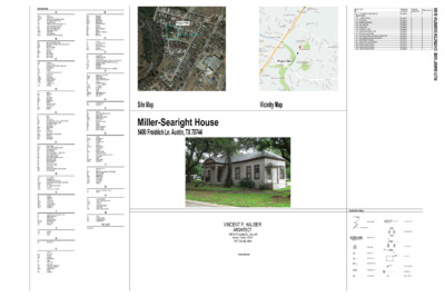
M MASONRY MATERIAL MAXIMUM MECHANICAL MEZZANINE MANUFACTURER MIDDLE MINIMUM MISCELLANEOUS MARK MASONRY OPENING METAL MOUNTED NORTH NOT APPLICABLE NEAR FACE NOT IN CONTRACT NOMINAL NOT TO SCALE ON CENTER OVERFLOW DRAIN OUTSIDE FACE OWNER FURNISHED CONTRACTOR INSTALLED OWNER FURNISHED OWNER INSTALLED OPPOSITE HAND OPENING OPPOSITE OVERFLOW THROUGH WALL SCUPPER PRE-CAST CONCRETE PERIMETER PERPENDICULAR POINT OF INTERSECTION PLATE PROPERTY LINE PLASTIC LAMINATE PLUMBING PLYWOOD PANEL PAIR PREFABRICATED PRELIMINARY PAINTED RADIUS REFLECTED CEILING PLAN ROOF DRAIN REFERENCE, REFER REINFORCING REQUIRED REVISION, REVISE ROOM ROUND ROUGH OPENING RADIUS POINT ROOF TOP UNIT SOUTH SCHEDULED SECTION SQUARE FEET SHEET SIMILAR SHEET METAL SAW JOINT SLOPE SPECIFICATION STAINLESS STEEL SOUND TRANSMISSION CLASS STANDARD STEEL STRUCTURAL SURFACE TREAD OR TOP TOP OF TEXAS ACCESSIBILITY STANDARDS TOP OF CURB TELEPHONE TEMPORARY THICKNESS THREADED THROUGH TYPICAL N O P Q R S T U V W MAS MATL MAX MECH MEZZ MFR MID MIN MISC MK MO MTL MTD N N/A NF NIC NOM NTS OC OD OF OFCI OFOI OH OPG OPP OS PC PERIM PERP PI P PL PLAM PLBG PLYWD PNL PR PREFAB PRELIM PTD R RCP RD REF REINF REQD REV RM RND RO RP RTU S SCHED SECT SF SHT SIM SHT MTL SJ SL SPEC SS STC STD STL STRUCT SURF T TO TAS TC TEL TEMP THK THRD THRU TYP VB VCT VERT VEST VR VT VTR w/ WC WH WP UON UR UNLESS OTHERWISE NOTED URINAL VAPOR BARRIER VINYL COMPOSITION TILE VERTICAL VESTIBULE VAPOR RETARDER VINYL TILE VENT THROUGH ROOF WITH WATER CLOSET WATER HEATER WORK POINT X,Y, & Z RESERVED A B C D E F G H I J K L ABBREVIATIONS: ABV ACOUST ACCU ACT AD ADA ADJ AFC AFF AHU ALUM AP ARCH ABOVE ACOUSTICAL AIR COOLED CONDENSING UNIT ACOUSTICAL CEILING TILE ACCESS DOOR AMERICAN WITH DISABILITIES ACT ADJUSTABLE OR ADJACENT ABOVE FINISHED CEILING ABOVE FINISHED FLOOR AIR HANDLING UNIT ALUMINUM ACCESS PANEL ARCHITECT, ARCHITECTURAL BFF BFE BLDG BOC BP BRG BRKT BS BW BO CAB CIP CJ CL CLG CLR CMU CO COL CONC CONST CONT CORR CT CTR D DEG DET DIA DIAG DIM DN DP DS DWG DWL E EA EF EIFS EFS EJ EL ELEC EQ EQUIP EW EWC EXIST EXP EXT FA FACP FCO FD FDC FDV FE FEC FF FG FH FHC FP F/R FRP FRT GALV GB GC GFRC GND GRS GTR GWB HT HB HC HDW HDWD HM HORIZ HYD BELOW FINISHED FLOOR BRACKET MOUNTED FIRE EXTINGUISHER BUILDING BACK OF CURB BASE PLATE BEARING BRACKET BOTH SIDES BOTH WAYS BOTTOM OF CABINET CAST IN PLACE CONTROL OR CONSTRUCTION JOINT CENTERLINE CEILING CLEAR CONCRETE MASONRY UNIT CLEAN OUT COLUMN CONCRETE CONSTRUCTION CONTINUOUS CORRIDOR CERAMIC TILE CENTER DEPTH DEGREES DETAIL DIAMETER DIAGONAL DIMENSION DOWN DAMP PROOFING DOWN SPOUT DRAWING DOWEL EAST EACH EACH FACE EXTERIOR INSULATION FINISH SYSTEM EXTERIOR FINISH SYSTEM EXPANSION JOINT ELEVATION ELECTRICAL EQUAL EQUIPMENT EACH WAY ELECTRIC WATER COOLER EXISTING EXPANSION EXTERIOR FIRE ALARM FIRE ALARM CONTROL PANEL FLOOR CLEAN OUT FLOOR DRAIN FIRE DEPARTMENT CONNECTION FIRE DEPARTMENT VALVE FIRE EXTINGUISHER FIRE EXTINGUISHER CABINET FINISHED FLOOR FINISHED GRADE FIRE HYDRANT FIRE HOSE CABINET FIRE PROTECTION FIRE RATED FIBERGLASS REINFORCED PLASTIC FIRE TREATED GALVANIZED GRADE BEAM GENERAL CONTRACTOR GLASS FIBER REINFORCED CONCRETE GROUND GALVANIZED RIGID STEEL GUTTER GYPSUM WALL BOARD HEIGHT HOSE BIB HANDICAP HARDWARE HARD WOOD HOLLOW METAL HORIZONTAL HYDRANT IBC ID IF IN INCAND INSUL INT INTERNATIONAL BUILDING CODE INSIDE DIAMETER INSIDE FACE INCH OR INCHES INCANDESCENT INSULATION INTERIOR JAN JST JT JANITOR JOIST JOINT KO KNOCKOUT L LAV LB,# LDG LF LG LH LL LLH LLV LONG LT LTG LENGTH LAVATORY POUNDS LANDING LINEAR FEET LONG LEFT HAND LIVE LOAD LONG LEG HORIZONTAL LONG LEG VERTICAL LONGITUDINAL LIGHT LIGHTING Project Site Project Site Issued for Construction Ammendments TITLE SHEET NO. G0.0 COVER SHEET AND SHEET LIST ARCHITECTURE A1.0 A1.1 A2.0 A2.1 A2.2 A2.3 A3.1 A4.1 A5.1 A6.1 A6.2 A7.1 A8.0 A8.1 A8.2 DEMO SITE PLAN SITE PLAN DEMO FLOOR PLAN FLOOR PLAN ROOF PLAN FRAMING PLANS REFLECTED CEILING PLAN BUILDING ELEVATIONS DOOR AND WINDOW SCHEDULE AND DETAILS INTERIOR ELEVATIONS AND DETAILS INTERIOR ELEVATIONS FINISH PLAN AND SCHEDULE RESTORATION DETAILS RESTORATION DETAILS RESTORATION DETAILS Permit and Pricing Set 01/28/2020 01/28/2020 01/28/2020 01/28/2020 01/28/2020 01/28/2020 01/28/2020 01/28/2020 01/28/2020 01/28/2020 01/28/2020 01/28/2020 01/28/2020 01/28/2020 01/28/2020 01/28/2020 0 2 0 2 - 8 2 - 1 0 S T N E M U C O D N O T C U R T S N O C I : I E S U O H T H G R A E S R E L L M - I QT QTY QUARRY TILE QUANTITY Site Map Vicinity Map Miller-Searight House 5400 Freidrich Ln. Austin, TX 78744 01.28.2020 VINCENT P. HAUSER ARCHITECT 2301 E Riverside Dr., Suite 80 Austin, Texas 78741 Ph 512-452-3041 # In Association with ARCHITECTURAL SYMBOLS: XXXX INACTIVE LEAF XX DETAIL NAME SCALE: X" = 1'-0" DRAWING TITLE MAIN ENTRY 101 XX X XXX PT 1G X ROOM NAME WINDOW TAG PARTITION TAG KEYED NOTE TAG FINISH NOTE TAG DELTA SYMBOL DOOR NUMBER FINISH FLOOR EL XXX'-X" ELEVATION TAGS X/AX.XX . X X X A X / X/AX.XX X/AX.XX . X X X A X / X/AX.XX . X X X A X / . X X X A X / ELEVATION TAGS SECTION TAGS X/AX.XX PLAN TAGS EL XX'-X" SPOT ELEVATION XX COLUMN TAG FINISH CHANGE 604 P R O P E R T Y L I N E CARPORT 604 entire house. POOL EXISTING SIDEWALK TO BE REMAIN EXISTING STUMP TO BE REMOVED EXISTING PORCH TO BE REMOVED 605 EXISTING SIDEWALK TO BE REMAIN 20" OAK EXISTING ROOM AND ROOF TO BE REMOVED 24" OAK 24" OAK PORCH 2 P R O P E R T Y L I N E 24" OAK EXISTING SIDEWALK TO REMAIN OAKS 606 608 OAK REMOVE EXISTING SIDEWALK FROM DRIVEWAY TO OFFICE WATER METER 20" OAK EXISTING ROOM AND ROOF TO BE REMOVED 1 H C R O P HOUSE 32" OAK OAK 608 LAUNDRY OFFICE POST OFFICE 610 32" OAK 24" OAK 610 EXISTING CANOPY AND PAVERS TO BE REMOVED. PATCH HOUSE WALL AND LAUNDRY WALL. EXISTING MANHOLE TO REMAIN. 34" OAK 18" OAK ALK W E SID OAK OAK EXISTING SIDEWALK TO BE REMOVED OAK OAK OAK OAK OAK OAK WATER WELL PROPERTY LINE 612 CEDAR ELM 612 01 SITE DEMO PLAN SCALE: 1/16" = 1'-0" NORTH 0'-0" 5'-0" 10'-0" 20'-0" 40'-0" GENERAL NOTES 1. Provide tree protection as required by the City of Austin for all oak trees in the construction area. 2. Prepare a staging plan for the project showing materials staging and spoils locations for review with the Owner prior to beginning work. 3. Notify and schedule potential utility shutdowns prior to any excavation or demolition work. 4. Trace and mark on Record Drawing all existing utility lines and locations. 5. Mark all new utility work on Record Drawings. 6. Route all work below grade so as not to damage tree root systems. 7. Provide all temporary utilities, monitor, repair and keep in good working order during construction. 8. Provide temporary security fence to secure the property during construction. 9. Provide erosion controls as reasonably required and as directed by the City of Austin. 10. Maintain access for the Owner and emergency vehicles during construction. VINCENT P. HAUSER ARCHITECT 2301 E. Riverside, Suite 80 Austin, TX 78741 512-452-3041 Site Plan Keyed Notes A. Major rooms and areas to be leveled B. Not used. C. Rebuild window sash to match existing, repair and rebuild jambs and re-rope weights as required. Reuse all existing trim, repaint as required. D. Level and repair porch. E. Repair porch framing, replace existing columns and deck. F. Remove interior partition G. Remove existing door and frame H. Remove plumbing fixture and associated piping I. Remove millwork and existing appliances. Cap any unused utility lines for future re-use. K. Excavate soil to provide 12" clear from the underside of the wood floor joists in the crawl space under the M. Remove existing exterior wall. Patch and repair areas for new waterproofing and siding. N. Remove existing window. SITE PLAN LEGEND Existing contour line Existing to be demolished Existing to remain 24" Existing tree to remain Property line Miller-Searight House 5400 Freidrich Ln. Austin, Texas 78744 PRELIMINARY - FOR PRICING ONLY THESE DOCUMENTS ARE FOR DESIGN REVIEW ONLY AND NOT INTENDED FOR CONSTRUCTION, OR PERMIT PURPOSES. THEY ARE PREPARED BY, OR UNDER THE DIRECTION OF: Vincent P. Hauser January 2020 I s s u e N o. 1 2 3 4 5 6 7 Revision Revision Revision Revision Revision Revision Revision R E V I S I O N S D a t e 12/04/2018 02/05/2019 08/05/2019 08/30/2019 10/08/2019 12/07/2019 01/28/2020 S H E E T I N F O R M A T I O N Date Job Number Scale Drawn Checked Approved Site Demo Plan scale: 1/16"=1'-0" 01/28/2020 CK VPH VPH T I T L E S H E E T A1.0 GENERAL NOTES 1. Provide tree protection as required by the City of Austin for all oak trees in the construction area. 2. Prepare a staging plan for the project showing materials staging and spoils locations for review with the Owner prior to beginning work. 3. Notify and schedule potential utility shutdowns prior to any excavation or demolition work. 4. Trace and mark on Record Drawing all existing utility lines and locations. 5. Mark all new utility work on Record Drawings. 6. Route all work below grade so as not to damage tree root systems. 7. Provide all temporary utilities, monitor, repair and keep in good working order during construction. 8. Provide temporary security fence to secure the property during construction. 9. Provide erosion controls as reasonably required and as directed by the City of Austin. 10. Maintain access for the Owner and emergency vehicles during construction. VINCENT P. HAUSER ARCHITECT 2301 E. Riverside, Suite 80 Austin, TX 78741 512-452-3041 Site Plan Keyed Notes A. Demolish existing deck, provide new sod B. No work in this area C. No work to street paving D. Remove shrubs as directed by the Architect E. Provide allowance for trench structures in existing sidewalk and new accessible paving. SITE PLAN LEGEND Existing contour line Existing to remain 24" Existing tree to remain Property line 604 P R O P E R T Y L I N E CARPORT 604 POOL EXISTING SIDEWALK TO REMAIN EXISTING SIDEWALK TO REMAIN 605 SIDEWALK 24" OAK 24" OAK P R O P E R T Y L I N E 24" OAK 606 606 CONCRETE WALKWAY NEW SOD NEW DECK AND STAIRS NEW CURB. FIELD VERIFY DIMENSIONS OAKS PROVIDE NEW HANDICAP STALL SIGN 20'-0" 5'-0" 20" OAK NEW DECK AND RAMP SIDEWALK 608 HOUSE 32" OAK OAK 1 H C R O P CLEAN OUT EXISTING AREA DRAIN BOX " 0 - ' 6 1 LAUNDRY MH OFFICE REPLACE EXISTING PAVING w/ CONC PAD CLEAN OUT EXISTING AREA DRAIN BOX FIELD VERIFY LOCATION OF EXISTING TREE 32" OAK 24" OAK 610 34" OAK 18" OAK OAK OAK OAK REMOVE EXISTING SIDEWALK. INFILL AREA WITH NEW SOD OAK OAK OAK OAK OAK 608 RESTRIPE EXISTING PARKING TO PROVIDE ADA STALL AND ACCESS AISLE " 0 - ' 1 1 " 0 - ' 5 V F " 8 - ' 9 POST OFFICE 610 WATER WELL PROPERTY LINE 612 CEDAR ELM NEW CURB. FIELD VERIFY DIMENSIONS 612 01 SITE PLAN SCALE: 1/16" = 1'-0" NORTH 0'-0" 5'-0" 10'-0" 20'-0" 40'-0" Miller-Searight House 5400 Freidrich Ln. Austin, Texas 78744 PRELIMINARY - FOR PRICING ONLY THESE DOCUMENTS ARE FOR DESIGN REVIEW ONLY AND NOT INTENDED FOR CONSTRUCTION, OR PERMIT PURPOSES. THEY ARE PREPARED BY, OR UNDER THE DIRECTION OF: Vincent P. Hauser January 2020 I s s u e N o. 1 2 3 4 5 6 7 Revision Revision Revision Revision Revision Revision Revision R E V I S I O N S D a t e 12/04/2018 02/05/2019 08/05/2019 08/30/2019 10/08/2019 12/07/2019 01/28/2020 S H E E T I N F O R M A T I O N Date Job Number Scale Drawn Checked Approved Site Plan scale: 1/16"=1'-0" 01/28/2020 CK VPH VPH T I T L E S H E E T A1.1 REMOVE EXISTING PARTIONS REMOVE EXISTING PARTIONS REMOVE EXISTING DOOR REMOVE EXISTING PARTIONS REMOVE EXISTING PARTIONS REMOVE EXISTING TUB AND ASSOCIATED PLUMBING REMOVE EXISTING DOOR REMOVE EXISTING LAVATORY AND WATER CLOSET REMOVE EXISTING PARTIONS REMOVE EXISTING DOOR 02 ENLARGED DEMO PLAN SCALE: 1/2" = 1'-0" M G K A F G I N M N N N P M N N A I K A K H H G F G G O G A F K K A A K O F C C D E EXISTING CONCRETE WALKWAY TO BE REMOVED EXISTING GAS METER M N G A REMOVE EXISTING RAMP AND PAVING M M N G REMOVE EXISTING STEPS M N K G G F F G F K A A K EXISTING MANHOLE AND COVER TO BE LEVELED. EXISTING PAVING TO BE REMOVED. EXISTING CANOPY ABOVE TO BE REMOVED 01 DEMO FLOOR PLAN SCALE: 1/8" = 1'-0" NORTH 0'-0" 5'-0" 10'-0" 20'-0" GENERAL NOTES: Scope of Work -Confirm completion of foundation work, repair augment as required during soil removal. -Stabilize and repair existing perimeter foundation and floor framing system, per structural drawings. Repair and reinforce interior floor framing, level to the extent feasible as determined in conjunction with the Architect. The initial design tolerance is assumed to be ¼”, to be modified in the field as conditions warrant. -The work will include removing exterior perimeter wood trim to expose foundation and framing conditions, some selective interior floor removal to expose and access interior framing and foundation conditions. Interior floor removal is not allowed in Rooms 100, 101, 102, 104. Interior floor removal will be allowed in Room 106, 107, 108, 109, 110, 113. Other locations may be available for access, subject to the Floor Leveling Plan to be provided by the Contractor. -All trim removed for leveling and repair purposes will be marked and stored by the Contractor on site for re-use and/or replication in the rebuild. In general, existing trim determined to be historic material will be re-sued. Material for the build-back will be either existing historic material, or new material milled to match historic material. Historic material determined by the Architect to be not suitable for re-use will be stored on site and delivered to the Owner at the completion of the work. Under no circumstances will any historic material be discarded or destroyed. FRAMING GENERAL NOTES AND MATERIAL: 1. Provide all wood framing and blocking required and install in compliance with the IRC for One and Two Family Residences as adopted by the City of Austin. 2. Lumber to be new stock, thoroughly seasoned and well manufactured, free from minor warp that cannot be corrected by bridging or blocking. 3. Structural framing to be No. 1 or better kd doug fir / larch / pine with end-rated fiber stress bending of 1,000 psi. 4. Unless otherwise shown on drawings or specifications, sizes of lumber shall be as follows: Framing: 2 x 6, 2 x 8, 2 x 10, 2 x 12, 4 x or 6 x to match existing sizes Blocking: 2 x 4 Bridging: 1 x 4 Studs: 2 x 4 Grounds: 1 1/2” wide Sleepers: 2 x 4 5. Lumber to be finished on all 4 sides. Sizes given on plans and in the specifications are nominal sizes. Minimum dressed dimensions shall comply with current American Lumber Standards. 6. Moisture content of framing lumber not to exceed 15% at the time of installation. 7. Board lumber to comply with WWPA and American Lumber Standards R 16-39 for the material specified unless revised prior to submitting a bid. Grade of board lumber to be suitable for its intended use. In general, lumber with knots, knot holes or splits should be culled from lumber delivered and not installed. 8. Provided treated lumber as required by the Codes. 9. Carefully lay out and erect structural members and other rough carpentry as necessary to install the finished work. All members shall be properly braced, plumbed and leveled. Use sufficient size and number of nails, screws, bolts and other fasteners to ensure the rigidity of the construction. Provide all temporary framing and bracing of new and existing construction required. 10. Provide a submittal for review and approval for all framing hardware proposed, including nails, bolts, lag bolts, Simpson connectors and similar; prior to ordering or purchasing material. 11. Do not compromise any framing by improper cutting or drilling. 12. All carpentry modifications by mechanical trades shall be corrected by the GC. 13. For wall framing generally: Nail studs to plates at a maximum spacing of 16” oc. Plywood sheathing generally should overlap and be nailed to plates. Where sheathing does not overlap plates, anchor as required and at a minimum provide steel straps or appropriate Simpson anchors at every other stud. Corner posts to be formed with no less that three studs to receive interior finishes. Provide adequate corner and other bracing to resist wall racking and other movement. 14. Unless shown or sized differently by the structural engineer, ceiling joists shall be a minimum dimension of 2 x 6. All joists should be properly toe-nailed to plates, every fourth joist and outrigger shall be connected to plate with steel straps or appropriate Simpson anchor. 15. Roof sheathing to be nailed to supports at 6” oc with minimum 6d box or cc nails. Provide blocking under plywood panel joints perpendicular to main framing members as required. 16. Provide solid blocking as required for all assemblies, including handrails, balusters, and around structural steel. 17. Post up and provide pony walls at all locations necessary to reduce strongback spans. All such construction shall bear on primary load bearing construction. 1. Remove and replace all rotting or missing siding and trim, match profiles of existing historic material. 2. All new material to be No 1 or better rift - or quarter - sawn doug fir, western red cedar or approved salvaged material. Provide a submittal and samples of all trim material for review and approval prior to ordering or purchasing and material. SIDING AND TRIM GENERAL NOTES: PAINTING GENERAL NOTES: for all new paint. 1. Remove all loose paint and repair or replace missing and rotted trim. Provide one color for the siding, two colors for trim. Provide a good mechanical base 2. Do not power wash anything prior to painting. 3. Paint system to be Sherwin Williams 100% acrylic, gloss or semi-gloss, three coat system. 4. Sealant to be one-part polyurethane or acrylic and demonstrated to be compatible with paint system. FLOOR PLAN KEYED NOTES: A. Major rooms and areas to be leveled B. Not used. C. Rebuild window sash to match existing, repair and rebuild jambs and re-rope weights as required. Reuse all existing trim, repaint as required. D. Level and repair porch. E. Repair porch framing, replace existing columns and deck. F. Remove interior partition G. Remove existing door and frame H. Remove plumbing fixture and associated piping I. Remove millwork and existing appliances. Cap any unused utility lines for future re-use. K. Excavate soil to provide 12" clear from the underside of the wood floor joists in the crawl space under the entire house. M. Remove existing exterior wall. Patch and repair areas for new waterproofing and siding. N. Remove existing window. O. Remove existing gypsum board to existing frame. Protect existing door opening and trim. P. Remove existing gypsum/plywood to expose existing window. Protect existing window trim. 2757 SF HOUSE SF: PORCH 1 SF: 109 SF PORCH 2 SF: 18 SF TOTAL SF: 2884 SF DEMO PLAN LEGEND Existing construction to be removed Existing construction to remain VINCENT P. HAUSER ARCHITECT 2301 E. Riverside, Suite 80 Austin, TX 78741 512-452-3041 Miller-Searight House 5400 Freidrich Ln. Austin, Texas 78744 PRELIMINARY - FOR PRICING ONLY THESE DOCUMENTS ARE FOR DESIGN REVIEW ONLY AND NOT INTENDED FOR CONSTRUCTION, OR PERMIT PURPOSES. THEY ARE PREPARED BY, OR UNDER THE DIRECTION OF: Vincent P. Hauser January 2020 I s s u e N o. 1 2 3 4 5 6 7 Revision Revision Revision Revision Revision Revision Revision R E V I S I O N S D a t e 12/04/2018 02/05/2019 08/05/2019 08/30/2019 10/08/2019 12/07/2019 01/28/2020 S H E E T I N F O R M A T I O N Date Job Number Scale Drawn Checked Approved Demo Floor Plan scale: varies 01/28/2020 CK VPH VPH T I T L E S H E E T A2.0 1 1/4" DIAMETER HANDRAIL 2X4 WOOD TOP RAIL CONTINUOUS WOOD BLOCKING 1X4 PICKETS, SPACED 2" BETWEEN EACH POST 4X4 WOOD POST 2X4 WOOD BOTTOM RAIL 2X6 WOOD DECK 2X6 CONTINUOUS WOOD BLOCKING 2X1/2" BOLTS AND NUTS SIMPSON POST BASE NEW CONCRETE SLAB 04 RAILING DETAIL SCALE: 3/4" = 1'-0" 3'-6 1/2" UPPER CABINETS 6'-10" BREAKROOM 107 107 4/A6.2 1/A6.2 10'-4 1/2" MICROWAVE AND HOOD ABOVE OVEN / RANGE CL " 0 - ' 1 " 0 - ' 2 7" FLUSH VALVE ON OPEN SIDE 36" GRAB BAR 42" GRAB BAR TOILET SEAT COVER DISPENSER TOILET PAPER DISPENSER 8 0 1 SANITARY NAPKIN DISPOSAL 2/A6.1 1 . 6 A / 1 1 . 6 A / 4 3/A6.1 TOILET 108 NEW MIRROR NEW LAVATORY AND FAUCET SOAP DISPENSER, WALL MOUNTED PAPER TOWEL DISPENSER, SEMI-RECESSED STORAGE CABINETS DISHWASHER 03 BREAK ROOM PLAN SCALE: 1/2" = 1'-0" 02 TOILET ROOM PLAN SCALE: 1/2" = 1'-0" 6 MEETING ROOM 4 103 5 4 103 B D 7 B C C 2 0 1 5 0 1 3 2 20 19 NEW CONCRETE SIDEWALK. MAX SLOPE 2% PER ADA DRIP LINE (13'-0") / 3 A 6 . 2 MEETING ROOM 3 102 / 2 A 6 . 2 FLAGSTONE PAVERS ON CONC BASE NEW WD DECK 14/A5.1 1 . 2 A 4 / CONTROL JOINTS @ 8'-0" 2/A4.1 A AC A A A WD DECK 113 1 4 / A 5 . 1 4 0 1 A A A A / 8 A 6 . 2 4/A2.1 1 . 2 A 4 / 1 4 / A 5 . 1 B B EXISTING 20" OAK WD DECK 112 14/A5.1 1 : 1 2 M A X S L O P E 112 WAITING ROOM 111 111 CORRIDOR 104 OPEN OLD WINDOW OPENING. PROVIDE PAINTED SHELVES 8 6 0 1 MEETING ROOM 2 106 FOYER 101 1 0 1 1 MEETING ROOM 1 105 / 5 A 6 . 2 6/A6.2 3/A2.1 A A 8 0 1 FRIDGE A 107 BREAKROOM 107 OVEN DW A A LAUNDRY 11 OFFICE 110 FILE ROOM & STORAGE 109 109 TOILET ROOM 108 16 AC 17 18 NEW WD RAMP 1 . 4 A 1 / EXISTING GAS METER EXISTING MANHOLE COVER NEW CONC PAD 10 9 PATCH SIDING TO MATCH EXISTING AT ROOF DEMO AREAS 12 13 AC 14 15 2/A2.1 01 FLOOR PLAN SCALE: 1/8" = 1'-0" NORTH 0'-0" 5'-0" 10'-0" 20'-0" GENERAL NOTES: Scope of Work Stabilize and repair existing perimeter foundation and floor framing system, per structural drawings. Repair and reinforce interior floor framing, level to the extent feasible as determined in conjunction with the Architect. The initial design tolerance is assumed to be ¼”, to be modified in the field as conditions warrant. The work will include removing exterior perimeter wood trim to expose foundation and framing conditions, some selective interior floor removal to expose and access interior framing and foundation conditions. Interior floor removal is not allowed in Rooms 100, 101, 102, 104. Interior floor removal will be allowed in Room 106, 107, 108, 109, 110, 113. Other locations may be available for access, subject to the Floor Leveling Plan to be provided by the Contractor. All trim removed for leveling and repair purposes will be marked and stored by the Contractor on site for re-use and/or replication in the rebuild. In general, existing trim determined to be historic material will be re-sued. Material for the build-back will be either existing historic material, or new material milled to match historic material. Historic material determined by the Architect to be not suitable for re-use will be stored on site and delivered to the Owner at the completion of the work. Under no circumstances will any historic material be discarded or destroyed. FRAMING GENERAL NOTES AND MATERIAL: 1. Provide all wood framing and blocking required and install in compliance with the IRC for One and Two Family Residences as adopted by the City of Austin. 2. Lumber to be new stock, thoroughly seasoned and well manufactured, free from minor warp that cannot be corrected by bridging or blocking. 3. Structural framing to be No. 1 or better kd doug fir / larch / pine with end-rated fiber stress bending of 1,000 psi. 4. Unless otherwise shown on drawings or specifications, sizes of lumber shall be as follows: Framing: 2 x 6, 2 x 8, 2 x 10, 2 x 12, 4 x or 6 x to match existing sizes Blocking: 2 x 4 Bridging: 1 x 4 Studs: 2 x 4 Grounds: 1 1/2” wide Sleepers: 2 x 4 5. Lumber to be finished on all 4 sides. Sizes given on plans and in the specifications are nominal sizes. Minimum dressed dimensions shall comply with current American Lumber Standards. 6. Moisture content of framing lumber not to exceed 15% at the time of installation. 7. Board lumber to comply with WWPA and American Lumber Standards R 16-39 for the material specified unless revised prior to submitting a bid. Grade of board lumber to be suitable for its intended use. In general, lumber with knots, knot holes or splits should be culled from lumber delivered and not installed. 8. Provided treated lumber as required by the Codes. 9. Carefully lay out and erect structural members and other rough carpentry as necessary to install the finished work. All members shall be properly braced, plumbed and leveled. Use sufficient size and number of nails, screws, bolts and other fasteners to ensure the rigidity of the construction. Provide all temporary framing and bracing of new and existing construction required. 10. Provide a submittal for review and approval for all framing hardware proposed, including nails, bolts, lag bolts, Simpson connectors and similar; prior to ordering or purchasing material. 11. Do not compromise any framing by improper cutting or drilling. 12. All carpentry modifications by mechanical trades shall be corrected by the GC. 13. For wall framing generally: Nail studs to plates at a maximum spacing of 16” oc. Plywood sheathing generally should overlap and be nailed to plates. Where sheathing does not overlap plates, anchor as required and at a minimum provide steel straps or appropriate Simpson anchors at every other stud. Corner posts to be formed with no less that three studs to receive interior finishes. Provide adequate corner and other bracing to resist wall racking and other movement. 14. Unless shown or sized differently by the structural engineer, ceiling joists shall be a minimum dimension of 2 x 6. All joists should be properly toe-nailed to plates, every fourth joist and outrigger shall be connected to plate with steel straps or appropriate Simpson anchor. 15. Roof sheathing to be nailed to supports at 6” oc with minimum 6d box or cc nails. Provide blocking under plywood panel joints perpendicular to main framing members as required. 16. Provide solid blocking as required for all assemblies, including handrails, balusters, and around structural steel. 17. Post up and provide pony walls at all locations necessary to reduce strongback spans. All such construction shall bear on primary load bearing construction. SIDING AND TRIM GENERAL NOTES: 1. Remove and replace all rotting or missing siding and trim, match profiles of existing historic material. 2. All new material to be No 1 or better rift - or quarter - sawn doug fir, western red cedar or approved salvaged material. Provide a submittal and samples of all trim material for review and approval prior to ordering or purchasing and material. 1. Remove all loose paint and repair or replace missing and rotted trim. Provide one color for the siding, two colors for trim. Provide a good mechanical base 2. Do not power wash anything prior to painting. 3. Paint system to be Sherwin Williams 100% acrylic, gloss or semi-gloss, three coat system. 4. Sealant to be one-part polyurethane or acrylic and demonstrated to be compatible with paint system. PAINTING GENERAL NOTES: for all new paint. 2757 SF HOUSE SF: PORCH 1 SF: 109 SF PORCH 2 SF: 18 SF TOTAL SF: 2884 SF FLOOR PLAN LEGEND Existing construction to remain New construction New concrete walkway VINCENT P. HAUSER ARCHITECT 2301 E. Riverside, Suite 80 Austin, TX 78741 512-452-3041 Miller-Searight House 5400 Freidrich Ln. Austin, Texas 78744 PRELIMINARY - FOR PRICING ONLY THESE DOCUMENTS ARE FOR DESIGN REVIEW ONLY AND NOT INTENDED FOR CONSTRUCTION, OR PERMIT PURPOSES. THEY ARE PREPARED BY, OR UNDER THE DIRECTION OF: Vincent P. Hauser January 2020 I s s u e N o. 1 2 3 4 5 6 7 Revision Revision Revision Revision Revision Revision Revision R E V I S I O N S D a t e 12/04/2018 02/05/2019 08/05/2019 08/30/2019 10/08/2019 12/07/2019 01/28/2020 S H E E T I N F O R M A T I O N Date Job Number Scale Drawn Checked Approved Floor Plan scale: varies A2.1 01/28/2020 CK VPH VPH T I T L E S H E E T GALVANIZED GUTTER AND DOWNSPOUTS, TYP. NEW METAL ROOFING SLOPE 2:12 NEW METAL ROOFING correction of his own work if it does not comply with the requirements or specifications. GALVANIZED GUTTER AND DOWNSPOUTS, TYP. PROVIDE 5/8" PLYWD DECK AT EXISTING ROOF, TYP. PROVIDE 2X6 WD COLLAR TIES AT EXISTING RAFTERS, TYP. GENERAL NOTES: 1. Provide allowance for repair of existing shingle roof to assure weathertight performance. 2. Provide allowance for 26 ga. Galvalume metal roofing. Provide samples for review and approval by the Owner prior to ordering material. 3. Provide allowance for 6” half-round galvalume gutter and downspout system. 4. Provide allowance for repair to all modified bitumen roofing to assure weathertight performance. FOR NEW ROOFING ALLOWANCE, PROVIDE FOR THE FOLLOWING: 1. Prepare substrate prior to beginning roofing installation including decking, framing and blocking and all assemblies including vents, flues skylight curbs and similar work. 2. All flashings shall be standard, or shall be custom fabricated if required for the application. 3. Prior to beginning roofing work, convene a pre-construction conference with the Owner. Review sequencing of work, installation methods and coordination with other trades. Review edge, ridge, vent, flashing and other details with the Owner. Coordinate with gutter installation. 4. Provide manufacturer's standard written materials. Warranty. Provide a five (5) year written installation warranty for roof, flashing and counterflashing, against defects in workmanship. The 5-year term shall commence upon acceptance of the roof by the Owner. During the 5-year term, the roof is to be maintained and kept in good repair by the Owner. Defects due to poor workmanship and materials shall be corrected by the Contractor at no cost to the Owner. 5. Provide minimum 30# roofing felt under roofing, 36” wide roll with galv nails and plates. Do not use staples on felt underlayment. 6. Examine all areas and conditions where work is to be performed. Correct all conditions detrimental to the proper execution of the work. Decking shall be securely attached to rafters with no gaps. Do not proceed until improper conditions are corrected. 7. When metal roofing work is begun it constitutes acceptance of the existing conditions and the installer will be responsible for corrections as well as 8. Lap roofing felt 4” at horizontal joints and 12” at vertical joints. Provide a minimum double thickness at valleys. 9. Allow the metal roofing sheet to extend 2”- 3” beyond the eave trim unless otherwise required to coordinate with gutter installation. Do not bend the lower end of the panels at the eaves, as this will close the v-drain. Fasten with lead - headed screws or other fasteners specifically recommended by roofing manufacturer. Install space all fasteners as required by the manufacturer. 10. Walk through and inspect the installation of the roof after completion and make al corrections before the roofer leaves the job. ROOF PLAN KEYED NOTES: Inspect and re-seal all roof penetrations A Remove existing shingles. Replace with new metal roofing. Montopolis Supply Co. Rain Gaurd Roofing panels. B C Inspect and repair all valley conditions. Inform the Architect of any soft spots and areas that may require repairs during an initial roof inspection. D Provide new 5/8" plywood deck over existing roof structure. E Provide 2x6 wood collar ties on existing roof rafters. PROVIDE 5/8" PLYWD DECK AT EXISTING ROOF, TYP. PROVIDE 2X6 WD COLLAR TIES AT EXISTING RAFTERS, TYP. NEW METAL ROOFING ROOF PLAN LEGEND Existing Roof to be Removed New metal roof Location of Exterior walls NEW METAL ROOFING OVER EXISTING ROOF STRUCTURE NEW METAL ROOFING OVER EXISTING ROOF STRUCTURE PROVIDE 5/8" PLYWD DECK AT EXISTING ROOF, TYP. PROVIDE 2X6 WD COLLAR TIES AT EXISTING RAFTERS, TYP. NEW METAL ROOFING SLOPE 2" PER 12" 14'-3" " 4 - ' 4 1 2 : 1 2 S L O P E 2 : 1 2 S L O P E E P O L S 2 1 : 2 GALVANIZED GUTTER AND DOWNSPOUTS, TYP. GALVANIZED GUTTER AND DOWNSPOUTS, TYP. NEW METAL ROOFING SLOPE 2" PER 12" GALVANIZED GUTTER AND DOWNSPOUTS, TYP. PROVIDE 2X6 WD COLLAR TIES AT EXISTING RAFTERS, TYP. 02 ROOF PLAN SCALE: 1/8" = 1'-0" NORTH 0'-0" 5'-0" 10'-0" 20'-0" ROOF AND DECK TO BE DEMOLISHED D E A A D E C C C A D E A ROOF AND DECK TO BE DEMOLISHED C D E C A C B A B C ROOF AND DECK TO BE DEMOLISHED 01 DEMO ROOF PLAN SCALE: 1/8" = 1'-0" NORTH 0'-0" 5'-0" 10'-0" 20'-0" COVERED WALKWAY TO BE REMOVED ROOF AND DECK TO BE DEMOLISHED A A VINCENT P. HAUSER ARCHITECT 2301 E. Riverside, Suite 80 Austin, TX 78741 512-452-3041 Miller-Searight House 5400 Freidrich Ln. Austin, Texas 78744 PRELIMINARY - FOR PRICING ONLY THESE DOCUMENTS ARE FOR DESIGN REVIEW ONLY AND NOT INTENDED FOR CONSTRUCTION, OR PERMIT PURPOSES. THEY ARE PREPARED BY, OR UNDER THE DIRECTION OF: Vincent P. Hauser September 2015 N o. I s s u e Issue for Permit R E V I S I O N S D a t e 12/17/2019 S H E E T I N F O R M A T I O N Date Job Number Scale Drawn Checked Approved Roof Plans scale: 1/8"=1'-0" A2.2 01/06/2020 CK VPH VPH T I T L E S H E E T 2x6 WD RAFTERS @ 24" O.C. FRAMING GENERAL NOTES AND MATERIAL: REFRAME WALL AT ATTIC LEVEL TO RECIEVE NEW STRUCTURE AND ROOF 2x8 WD VALLEY RAFTER PROVIDE 2X6 WD COLLAR TIES AT EXISTING RAFTERS PROVIDE 5/8" PLYWD DECK OVER EXISTING RAFTERS POST UP RIDGE w/ DOUBLE 2X4 COLUMN AT BEARING WALLS - TYP. LOAD-BEARING WALLS SHOWN DASHED POST UP RIDGE w/ DOUBLE 2X4 COLUMN AT BEARING WALLS - TYP. PROVIDE 2X6 WD COLLAR TIES AT EXISTING RAFTERS. PROVIDE 5/8" PLYWD DECK OVER EXISTING RAFTERS POST UP RIDGE w/ DOUBLE 2X4 COLUMN AT BEARING WALLS - TYP. PROVIDE 2X6 WD COLLAR TIES AT EXISTING RAFTERS. PROVIDE 5/8" PLYWD DECK OVER EXISTING RAFTERS PROVIDE 2X6 WD COLLAR TIES AT EXISTING RAFTERS. PROVIDE 5/8" PLYWD DECK OVER EXISTING RAFTERS 2x6 WD RAFTERS @ 24" O.C. 2X8 WD RAFTER PROVIDE 2X6 WD COLLAR TIES AT EXISTING RAFTERS. PROVIDE 5/8" PLYWD DECK OVER EXISTING RAFTERS 2x6 WD RAFTERS @ 24" O.C. REFRAME WALL AT ATTIC LEVEL TO RECIEVE NEW STRUCTURE AND ROOF 0'-0" 5'-0" 10'-0" 20'-0" SIDING AND TRIM GENERAL NOTES: PROVIDE 2X6 WD COLLAR TIES AT EXISTING RAFTERS. PROVIDE 5/8" PLYWD DECK OVER EXISTING RAFTERS 02 ROOF FRAMING PLAN SCALE: 1/8" = 1'-0" NORTH 2x4 WD FRMAING @ 16" O.C. AT ALL NEW WALLS MEETING ROOM 4 103 1. Remove all loose paint and repair or replace missing and rotted trim. Provide one color for the siding, two colors for trim. Provide a good mechanical base 2. Do not power wash anything prior to painting. 3. Paint system to be Sherwin Williams 100% acrylic, gloss or semi-gloss, three coat system. 4. Sealant to be one-part polyurethane or acrylic and demonstrated to be compatible with paint system. GENERAL NOTES: Scope of Work -Confirm completion of foundation work. Repair and augment as required during soil removal. -Stabilize and repair existing perimeter foundation and floor framing system, per structural drawings. VINCENT P. HAUSER ARCHITECT -Repair and reinforce interior floor framing, level to the extent feasible as determined in conjunction with the Architect. The initial design tolerance is assumed to be ¼”, to be modified in the field as conditions warrant. 2301 E. Riverside, Suite 80 Austin, TX 78741 -The work will include removing exterior perimeter wood trim to expose foundation and framing conditions, some selective interior floor removal to expose and access interior framing and foundation conditions. Interior floor removal is not allowed in Rooms 100, 101, 102, 104. Interior floor removal will be allowed in Room 106, 107, 108, 109, 110, 113. Other locations may be available for access, subject to the Floor Leveling Plan to be provided by the Contractor. 512-452-3041 -All trim removed for leveling and repair purposes will be marked and stored by the Contractor on site for re-use and/or replication in the rebuild. In general, existing trim determined to be historic material will be re-sued. Material for the build-back will be either existing historic material, or new material milled to match historic material. Historic material determined by the Architect to be not suitable for re-use will be stored on site and delivered to the Owner at the completion of the work. Under no circumstances will any historic material be discarded or destroyed. 1. Provide all wood framing and blocking required and install in compliance with the IRC for One and Two Family Residences as adopted by the City of Austin. 2. Lumber to be new stock, thoroughly seasoned and well manufactured, free from minor warp that cannot be corrected by bridging or blocking. 3. Structural framing to be No. 1 or better kd doug fir / larch / pine with end-rated fiber stress bending of 1,000 psi. 4. Unless otherwise shown on drawings or specifications, sizes of lumber shall be as follows: Framing: 2 x 6, 2 x 8, 2 x 10, 2 x 12, 4 x or 6 x to match existing sizes Blocking: 2 x 4 Bridging: 1 x 4 Studs: 2 x 4 Grounds: 1 1/2” wide Sleepers: 2 x 4 5. Lumber to be finished on all 4 sides. Sizes given on plans and in the specifications are nominal sizes. Minimum dressed dimensions shall comply with current American Lumber Standards. 6. Moisture content of framing lumber not to exceed 15% at the time of installation. 7. Board lumber to comply with WWPA and American Lumber Standards R 16-39 for the material specified unless revised prior to submitting a bid. Grade of board lumber to be suitable for its intended use. In general, lumber with knots, knot holes or splits should be culled from lumber delivered and not installed. 8. Provided treated lumber as required by the Codes. 9. Carefully lay out and erect structural members and other rough carpentry as necessary to install the finished work. All members shall be properly braced, plumbed and leveled. Use sufficient size and number of nails, screws, bolts and other fasteners to ensure the rigidity of the construction. Provide all temporary framing and bracing of new and existing construction required. 10. Provide a submittal for review and approval for all framing hardware proposed, including nails, bolts, lag bolts, Simpson connectors and similar; prior to ordering or purchasing material. 11. Do not compromise any framing by improper cutting or drilling. 12. All carpentry modifications by mechanical trades shall be corrected by the GC. 13. For wall framing generally: Nail studs to plates at a maximum spacing of 16” oc. Plywood sheathing generally should overlap and be nailed to plates. Where sheathing does not overlap plates, anchor as required and at a minimum provide steel straps or appropriate Simpson anchors at every other stud. Corner posts to be formed with no less that three studs to receive interior finishes. Provide adequate corner and other bracing to resist wall racking and other movement. 14. Unless shown or sized differently by the structural engineer, ceiling joists shall be a minimum dimension of 2 x 6. All joists should be properly toe-nailed to plates, every fourth joist and outrigger shall be connected to plate with steel straps or appropriate Simpson anchor. 15. Roof sheathing to be nailed to supports at 6” oc with minimum 6d box or cc nails. Provide blocking under plywood panel joints perpendicular to main framing members as required. 16. Provide solid blocking as required for all assemblies, including handrails, balusters, and around structural steel. 17. Post up and provide pony walls at all locations necessary to reduce strongback spans. All such construction shall bear on primary load bearing construction. 1. Remove and replace all rotting or missing siding and trim, match profiles of existing historic material. 2. All new material to be No 1 or better rift - or quarter - sawn doug fir, western red cedar or approved salvaged material. Provide a submittal and samples of all trim material for review and approval prior to ordering or purchasing and material. PAINTING GENERAL NOTES: for all new paint. 2757 SF HOUSE SF: PORCH 1 SF: 109 SF PORCH 2 SF: 18 SF TOTAL SF: 2884 SF FLOOR PLAN LEGEND Existing construction to remain New construction New concrete walkway Load-bearing walls Miller-Searight House 5400 Freidrich Ln. Austin, Texas 78744 PRELIMINARY - FOR PRICING ONLY THESE DOCUMENTS ARE FOR DESIGN REVIEW ONLY AND NOT INTENDED FOR CONSTRUCTION, OR PERMIT PURPOSES. THEY ARE PREPARED BY, OR UNDER THE DIRECTION OF: Vincent P. Hauser January 2020 I s s u e N o. 1 2 3 4 5 6 7 Revision Revision Revision Revision Revision Revision Revision R E V I S I O N S D a t e 12/04/2018 02/05/2019 08/05/2019 08/30/2019 10/08/2019 12/07/2019 01/28/2020 S H E E T I N F O R M A T I O N Date Job Number Scale Drawn Checked Approved Framing Plan scale: varies A2.3 01/28/2020 CK VPH VPH T I T L E S H E E T 2X8 WD FLOOR JOISTS @ 16" O.C AC 103 2X8 WD FLOOR JOISTS @ 16" O.C DOUBLE 2X8 WD BEAM DECK 113 4 0 1 CORRIDOR 104 2 0 1 5 0 1 MEETING ROOM 3 102 FOYER 101 MEETING ROOM 1 105 2X8 WD FLOOR JOISTS @ 16" O.C DOUBLE 2X10 WD BEAM 1 : 1 2 M A X S L O P E DECK 112 112 WAITING ROOM 111 111 FRIDGE 107 BREAKROOM 107 OVEN DW 6 0 1 MEETING ROOM 2 106 8 0 1 2x4 WD FRMAING @ 16" O.C. AT ALL NEW WALLS LAUNDRY 114 OFFICE 110 FILE ROOM & STORAGE 109 TOILET ROOM 108 AC 109 AC 01 FLOOR FRAMING PLAN NORTH SCALE: 1/8" = 1'-0" 0'-0" 5'-0" 10'-0" 20'-0" MEETING ROOM 4 103 EXTERIOR GRADE GFCI AC D $ EXTERIOR GRADE $ PROVIDE UNDER CABINET LIGHTS IN BREAKROOM MEETING ROOM 3 102 CORRIDOR 104 $ $ FOYER 101 $ $ $ $ WAITING ROOM 111 GFCI FRIDGE GFCI @ 40" AFF $$ GFCI BREAKROOM 107 $ OVEN $ DW $$ GFCI $ $ GFCI @ 40" AFF MEETING ROOM 2 106 MEETING ROOM 1 105 EP $ OFFICE 110 FILE ROOM & STORAGE 109 GFCI TOILET 108 AC D GFCI DISCONNECT ELECTRICAL SERVICE AND METER EXTERIOR GRADE RECEPTACLE EXTERIOR GRADE AC GENERAL NOTES: Scope of Work Stabilize and repair existing perimeter foundation and floor framing system, per structural drawings. Repair and reinforce interior floor framing, level to the extent feasible as determined in conjunction with the Architect. The initial design tolerance is assumed to be ¼”, to be modified in the field as conditions warrant. The work will include removing exterior perimeter wood trim to expose foundation and framing conditions, some selective interior floor removal to expose and access interior framing and foundation conditions. Interior floor removal is not allowed in Rooms 100, 101, 102, 104. Interior floor removal will be allowed in Room 106, 107, 108, 109, 110, 113. Other locations may be available for access, subject to the Floor Leveling Plan to be provided by the Contractor. All trim removed for leveling and repair purposes will be marked and stored by the Contractor on site for re-use and/or replication in the rebuild. In general, existing trim determined to be historic material will be re-sued. Material for the build-back will be either existing historic material, or new material milled to match historic material. Historic material determined by the Architect to be not suitable for re-use will be stored on site and delivered to the Owner at the completion of the work. Under no circumstances will any historic material be discarded or destroyed. FRAMING GENERAL NOTES AND MATERIAL: 1. Provide all wood framing and blocking required and install in compliance with the IRC for One and Two Family Residences as adopted by the City of Austin. 2. Lumber to be new stock, thoroughly seasoned and well manufactured, free from minor warp that cannot be corrected by bridging or blocking. 3. Structural framing to be No. 1 or better kd doug fir / larch / pine with end-rated fiber stress bending of 1,000 psi. 4. Unless otherwise shown on drawings or specifications, sizes of lumber shall be as follows: Framing: 2 x 6, 2 x 8, 2 x 10, 2 x 12, 4 x or 6 x to match existing sizes Blocking: 2 x 4 Bridging: 1 x 4 Studs: 2 x 4 Grounds: 1 1/2” wide Sleepers: 2 x 4 5. Lumber to be finished on all 4 sides. Sizes given on plans and in the specifications are nominal sizes. Minimum dressed dimensions shall comply with current American Lumber Standards. 6. Moisture content of framing lumber not to exceed 15% at the time of installation. 7. Board lumber to comply with WWPA and American Lumber Standards R 16-39 for the material specified unless revised prior to submitting a bid. Grade of board lumber to be suitable for its intended use. In general, lumber with knots, knot holes or splits should be culled from lumber delivered and not installed. 8. Provided treated lumber as required by the Codes. 9. Carefully lay out and erect structural members and other rough carpentry as necessary to install the finished work. All members shall be properly braced, plumbed and leveled. Use sufficient size and number of nails, screws, bolts and other fasteners to ensure the rigidity of the construction. Provide all temporary framing and bracing of new and existing construction required. 10. Provide a submittal for review and approval for all framing hardware proposed, including nails, bolts, lag bolts, Simpson connectors and similar; prior to ordering or purchasing material. 11. Do not compromise any framing by improper cutting or drilling. 12. All carpentry modifications by mechanical trades shall be corrected by the GC. 13. For wall framing generally: Nail studs to plates at a maximum spacing of 16” oc. Plywood sheathing generally should overlap and be nailed to plates. Where sheathing does not overlap plates, anchor as required and at a minimum provide steel straps or appropriate Simpson anchors at every other stud. Corner posts to be formed with no less that three studs to receive interior finishes. Provide adequate corner and other bracing to resist wall racking and other movement. 14. Unless shown or sized differently by the structural engineer, ceiling joists shall be a minimum dimension of 2 x 6. All joists should be properly toe-nailed to plates, every fourth joist and outrigger shall be connected to plate with steel straps or appropriate Simpson anchor. 15. Roof sheathing to be nailed to supports at 6” oc with minimum 6d box or cc nails. Provide blocking under plywood panel joints perpendicular to main framing members as required. 16. Provide solid blocking as required for all assemblies, including handrails, balusters, and around structural steel. 17. Post up and provide pony walls at all locations necessary to reduce strongback spans. All such construction shall bear on primary load bearing construction. 1. Remove and replace all rotting or missing siding and trim, match profiles of existing historic material. 2. All new material to be No 1 or better rift - or quarter - sawn doug fir, western red cedar or approved salvaged material. Provide a submittal and samples of all trim material for review and approval prior to ordering or purchasing and material. 1. Remove all loose paint and repair or replace missing and rotted trim. Provide one color for the siding, two colors for trim. Provide a good mechanical base 2. Do not power wash anything prior to painting. 3. Paint system to be Sherwin Williams 100% acrylic, gloss or semi-gloss, three coat system. 4. Sealant to be one-part polyurethane or acrylic and demonstrated to be compatible with paint system. PAINTING GENERAL NOTES: for all new paint. 2757 SF HOUSE SF: PORCH 1 SF: 109 SF PORCH 2 SF: 18 SF TOTAL SF: 2884 SF FLOOR PLAN LEGEND Existing construction to remain New construction New hard ceiling (gypsum board) New 6" light fixture Wall Sconces light fixture New Exhaust Fan New Air Supply Diffuser D Electrical Disconnect 02 ELECTRICAL PLAN SCALE: 1/8" = 1'-0" SIDING AND TRIM GENERAL NOTES: NOTE: PROVIDE 220 V RECEPTACLES FOR ALL APPLIANCES LINE OF ROOF LINE ABOVE MEETING ROOM 4 103 PROVIDE 3/4" PLYWD DECK FOR MECHANICAL EQUIPMENT NEW ACCESS PANEL AC UNIT ABOVE CEILING LINE OF ROOF LINE ABOVE COORDINATE LIGHT FIXTURE LOCATIONS WITH WD JOISTS COORDINATE LIGHT FIXTURE LOCATIONS WITH WD JOISTS FLOOD LIGHT IN BREAK ROOM CABINET MEETING ROOM 3 102 CORRIDOR 104 NEW ACCESS PANEL FOYER 101 EXISTING CHANDELIER LINE OF ROOF LINE ABOVE WAITING ROOM 111 BREAKROOM 107 MEETING ROOM 2 106 AC UNIT ABOVE CEILING MEETING ROOM 1 105 OFFICE 110 FILE ROOM & STORAGE 109 TOILET 108 PROVIDE 3/4" PLYWD DECK FOR MECHANICAL EQUIPMENT 01 REFLECTED CEILING PLAN SCALE: 1/8" = 1'-0" PATCH SIDING TO MATCH EXISTING AT ROOF DEMO AREAS VINCENT P. HAUSER ARCHITECT 2301 E. Riverside, Suite 80 Austin, TX 78741 512-452-3041 Miller-Searight House 5400 Freidrich Ln. Austin, Texas 78744 PRELIMINARY - FOR PRICING ONLY THESE DOCUMENTS ARE FOR DESIGN REVIEW ONLY AND NOT INTENDED FOR CONSTRUCTION, OR PERMIT PURPOSES. THEY ARE PREPARED BY, OR UNDER THE DIRECTION OF: Vincent P. Hauser January 2020 I s s u e N o. 1 2 3 4 5 6 7 Revision Revision Revision Revision Revision Revision Revision R E V I S I O N S D a t e 12/04/2018 02/05/2019 08/05/2019 08/30/2019 10/08/2019 12/07/2019 01/28/2020 S H E E T I N F O R M A T I O N Date Job Number Scale Drawn Checked Approved Reflected Ceiling Plan scale: varies 01/28/2020 CK VPH VPH T I T L E S H E E T A3.1 EXISTING ROOF CONSTRUCTION EXISTING ROOF WD SOFFIT " 6 VINCENT P. HAUSER ARCHITECT 2301 E. Riverside, Suite 80 Austin, TX 78741 512-452-3041 MTL ROOF 1/2" PLYWD SHEATHING FLASHING 6" 1/2 ROUND GALVANIZED GUTTER AND DOWNSPOUT SLOPE AT 1/4" PER FOOT SOFFIT VENT PAINTED HARDIE BOARD SIDING FLAT TRIM AT EAVE TO MATCH EXISTING HOLD DOWNSPOUT 2-1/2" FROM FACADE PRE-FINISHED GUTTERS AND DOWNSPOUTS - TYP EXISTING BOARD & BATTEN HOUSE EXISTING WINDOW PRE-FINISHED MTL GUTTER AND DOWNSPOUTS NEW WALL SCONCES EXISTING BOARD & BATTEN HOUSE EXISTING WINDOW 7 6 EXISTING HOUSE ASPHALT SHINGLE ROOF NEW V-CRIMP METAL ROOF SYSTEM OVER NEW PORCH - 24" O.C. EXISTING HOUSE ASPHALT SHINGLE ROOF EXISTING HOUSE ASPHALT SHINGLE ROOF PRE-FINISHED GUTTERS AND DOWNSPOUTS - TYP 1 . 4 A / 3 NEW WALL SCONCES NEW WD SIDING A A A A A NEW WD SIDING NEW RAMP AND DECK 11 EXISTING HOUSE ASPHALT SHINGLE ROOF NEW V-CRIMP METAL ROOF SYSTEM - 24" O.C. EXISTING HOUSE ASPHALT SHINGLE ROOF . 1 4 A 3 / NEW V-CRIMP METAL ROOF SYSTEM - 24" O.C. PRE-FINISHED MTL GUTTER AND DOWNSPOUTS NEW WALL SCONCES NEW WD LAP SIDING NEW WD LAP SIDING NEW WD LAP SIDING A A A A B 9 10 NEW STAIRS AND DECK B 1'-0" " 6 - ' 3 " 0 - ' 3 NEW RAILING AND DECK NEW RAILING AND DECK 03 ROOF DETAIL SCALE: 1-1/2" = 1'-0" NEW WALL SCONCES TOP OF EXISTING PLATE EL 113'-3" PRE-FINISHED GUTTERS AND DOWNSPOUTS - TYP PATCH & REPAIR SIDING AT ROOF DEMO AREA TO MATCH EXISTING EXISTING BOARD & BATTEN HOUSE EXISTING WINDOW FINISH GRADE EL 100'-0" 02 WEST ELEVATION SCALE: 1/4" = 1'-0" Miller-Searight House 5400 Freidrich Ln. Austin, Texas 78744 PRELIMINARY - FOR PRICING ONLY THESE DOCUMENTS ARE FOR DESIGN REVIEW ONLY AND NOT INTENDED FOR CONSTRUCTION, OR PERMIT PURPOSES. THEY ARE PREPARED BY, OR UNDER THE DIRECTION OF: Vincent P. Hauser January 2020 I s s u e N o. 1 2 3 4 5 6 7 Revision Revision Revision Revision Revision Revision Revision R E V I S I O N S D a t e 12/04/2018 02/05/2019 08/05/2019 08/30/2019 10/08/2019 12/07/2019 01/28/2020 S H E E T I N F O R M A T I O N TOP OF EXISTING PLATE EL 113'-3" Date Job Number Scale Drawn Checked Approved EXISTING BOARD & BATTEN HOUSE EXISTING WINDOW NEW RAMP AND DECK Building Elevations scale: varies 01/28/2020 CK VPH VPH T I T L E S H E E T FINISH GRADE EL 100'-0" 01 SOUTH ELEVATION SCALE: 1/4" = 1'-0" A4.1 5 5 5 5 5 5 5 5 5 5 5 5 5 D E H C S F E R INTERIOR SIDELIGHTS. RESTORE EXISTING MATCH EXISTING SIZE AND FUNCTION WEATHER BARRIER EXTERIOR SHEATHING WD LAP SIDING SEALANT AND BACKER ROD WD WINDOW FRAME WD WINDOW FRAME EXTERIOR SHEATHING WEATHER BARRIER WD WINDOW FRAME WINDOW SILL PER MFG SEALANT AND BACKER ROD EXTERIOR SHEATHING WEATHER BARRIER EXISTING WD EXISTING WD EXISTING WD REPAIR AND RESTORE EXISTING WINDOW FRAME. MATCH EXISTING HISTORIC WINDOWS WINDOW SCHEDULE SIZE MARK X MATERIAL FRAME SASH DETAIL REFERENCE REMARKS A B 1 2 3 4 5 6 7 8 9 10 11 12 13 14 15 16 17 18 19 20 WIDTH HEIGHT 3'-6" 6'-0" 7'-0" 3'-0" 6'-0" 3'-4" 3'-4" 3'-4" 3'-4" 3'-4" 3'-4" 3'-4" 3'-4" 3'-4" 3'-4" 3'-4" 3'-4" 3'-4" 2'-6" 3'-4" 3'-4" 3'-4" 3'-4" 7'-0" 6'-5" 6'-5" 6'-5" 6'-5" 6'-5" 6'-5" 6'-5" 6'-5" 6'-5" 6'-5" 6'-5" 6'-5" 6'-5" 2'-10" 6'-5" 6'-5" 6'-5" 6'-5" VINYL VINYL VINYL VINYL VINYL VINYL VINYL VINYL VINYL VINYL VINYL VINYL VINYL VINYL VINYL VINYL VINYL VINYL VINYL VINYL VINYL VINYL VINYL VINYL VINYL VINYL VINYL VINYL VINYL VINYL VINYL VINYL VINYL VINYL VINYL VINYL VINYL VINYL VINYL VINYL VINYL VINYL VINYL VINYL VINYL VINYL VINYL VINYL VINYL VINYL VINYL VINYL VINYL VINYL VINYL VINYL VINYL VINYL VINYL VINYL VINYL VINYL VINYL HEAD 13/A5.1 13/A5.1 EXIST 13/A5.1 13/A5.1 13/A5.1 13/A5.1 13/A5.1 13/A5.1 13/A5.1 13/A5.1 13/A5.1 13/A5.1 13/A5.1 13/A5.1 13/A5.1 13/A5.1 13/A5.1 13/A5.1 13/A5.1 JAMB 12/A5.1 12/A5.1 EXIST 12/A5.1 12/A5.1 12/A5.1 12/A5.1 12/A5.1 12/A5.1 12/A5.1 12/A5.1 12/A5.1 12/A5.1 12/A5.1 12/A5.1 12/A5.1 12/A5.1 12/A5.1 12/A5.1 12/A5.1 SILL 11/A5.1 11/A5.1 EXIST 11/A5.1 11/A5.1 11/A5.1 11/A5.1 11/A5.1 11/A5.1 11/A5.1 11/A5.1 11/A5.1 11/A5.1 11/A5.1 11/A5.1 11/A5.1 11/A5.1 11/A5.1 11/A5.1 11/A5.1 DOOR SCHEDULE X MARK DOOR FRAME HARDWARE DETAIL REFERENCE REMARKS SIZE MATERIAL S S A L G & M U N M U L A I 3 R O O D M A L P M R E H T 4 L A T E M W O L L O H 1 S S A L G & D O O W 2 E C N E R E F E R - D O O W I I H S N F R O R E T N I I E L U D E H C S I D E Z D O N A R A E L C = A C S S A L G = L G I I T N A P = T P N A T S = T S FINISH MATERIAL L A T E M W O L L O H 1 I M U N M U L A D O O W 2 I I E T A N M A L C T S A L P = L P D E Z D O N A R A E L C = A C I I T N A P = T P S S A L G = L G FINISH HARDWARE SETS PENDING OWNER APPROVAL** DOOR NUMBER WIDTH HEIGHT HEAD JAMB THRESHOLD L E B A L - I G N T A R E P Y T EXG DT2 DT2 DT1 DT2 DT1 DT1 DT3 DT1 DT1 DT1 DT1 EXG 6'-0" 6'-0" 3'-0" 6'-0" 3'-0" 3'-0" 3'-0" 3'-0" 3'-0" 3'-0" 3'-0" S S E N K C H T I EXG 1 3/4" 1 3/4" 1 3/4" 1 3/4" 1 3/4" 1 3/4" 1 3/4" 1 3/4" 1 3/4" 1 3/4" 1 3/4" EXG 6'-8" 6'-8" 6'-8" 6'-8" 6'-8" 6'-8" 6'-8" 6'-8" 6'-8" 6'-8" 6'-8" 101 102 103 104 105 106 107 108 109 110 111 112 NOTE: REPAIR AND REPAINT EXISTING DOORS SHOWN TO REMAIN E P Y T FT1 FT1 FT1 FT1 FT1 FT1 FT1 FT1 FT1 FT1 FT1 FT1 ST ST ST ST ST ST ST ST ST ST ST ST 3 3 3 3 3 3 3 3 3 3 3 3 3 CA CA CA CA CA CA CA CA CA CA CA CA XX** XX** XX** XX** XX** XX** XX** XX** XX** XX** XX** XX** 9/A5.1 8/A5.1 7/A5.1 9/A5.1 9/A5.1 9/A5.1 9/A5.1 9/A5.1 9/A5.1 9/A5.1 8/A5.1 8/A5.1 8/A5.1 8/A5.1 8/A5.1 8/A5.1 8/A5.1 7/A5.1 RESTORE EXISTING ENTRY DOOR 3'-0" X 6'-0" PAIR DOUBLE POCKET DOOR 3'-0" X 6'-0" PAIR DOUBLE POCKET DOOR 3'-0" X 6'-0" PAIR DOUBLE POCKET DOOR VINCENT P. HAUSER ARCHITECT 2301 E. Riverside, Suite 80 Austin, TX 78741 512-452-3041 MTL ROOF 2 1/2" RIGID INSUL 1/2" PLYWD SHEATHING FLASHING GALVANIZED GUTTER AND DOWNSPOUT SLOPE AT 1/4" PER FOOT FLAT TRIM AT EAVE TO MATCH EXISTING HOLD DOWNSPOUT 2 1/2" FROM FACADE 15/A5.1 MTL ROOF 2 1/2" RIGID INSUL TOP PLATE EL 108'-3" SOFFIT VENT WEATHER BARRIER 1/2" PLYWD SHEATHING 1x6 WD LAP SIDING TO MATCH EXISTING SS FLASHING WD WATER TABLE NEW FOUNDATION #5 REBAR - TOP AND BOTTOM #3 STIRRUPS @ 18" OC #3 BARS @ 18" OC FINISH FLOOR EL 100'-0" REF PARTITION TYPES REF PARTITION TYPES WD TRIM TO MATCH HISTORIC PROFILE - TYP. DOUBLE STUDS WD FRAME DOOR AS SCHED . . V F " 8 7 / 5 T H G E H I R O O D D E H C S DOUBLE STUDS WD FRAME DOOR AS SCHED . . V F " 8 7 / 3 H T D W I R O O D D E H C S DOOR AS SCHED ACCESSIBLE THRESHOLD WD DECK " 4 / 1 WEATHER BARRIER 3/4" TRIM BOARD X A M " 2 / 1 INTERIOR FINISH FLOOR WD JOISTS TOP PLATE - REF STRUCT SECURE DBL STUDS TO STRUCT ABOVE PROVIDE ONE JAMB ANCHOR ABOVE EACH HINGE AND BELOW TOP HINGE. LOCATION OF ANCHORS ON STRIKE JAMBS TO BE IDENTICAL 13 WINDOW HEAD DETAIL SCALE: 3"= 1'-0" 09 DOOR HEADER DETAIL SCALE: 1 1/2" = 1'-0" 08 DOOR JAMB DETAIL SCALE: 1 1/2" = 1'-0" 07 THRESHOLD DETAIL SCALE: 1 1/2" = 1'-0" 15 ROOF EDGE DETAIL SCALE: 3/4" = 1'-0" " 8 / 5 5 WD TRIM 1-1/2" PROUD OF FACE " 4 1 1 " 5" " 1 - ' 1 3 7/8" 12 WINDOW JAMB DETAIL SCALE: 3" = 1'-0" REF DOOR 1 1/2" " 2 / 1 1 R O O D F E R " 5 " 5 " 1 - ' 3 REF SCHED REF SCHED 5" 5" 5" 5" REF SCHED 5" 5" " 5 " 5 " 5 " 5 " 1 - ' 3 " 1 - ' 3 D E H C S F E R FT 1 TYPICAL SINGLE OR PAIR " 0 1 DT 3 " 0 1 DT 2 FINISH FLOOR " 0 1 DT 1 SOLID CORE WD DOUBLE POCKET DOOR 2 PANEL 2 VISION PANEL SOLID CORE WD 2 VISION PANEL 2X6 WD FRAMING TOP PLATE 2X6 WD FRAMING BATT INSUL - R-13 5/8" GWB 2X8 WD BEAMS 2X8 WD FLOOR JOIST A 10 HISTORIC DETAILS SCALE: 1/2" = 1'-0" 11 WINDOW SILL DETAIL SCALE: 3" = 1'-0" 3'-6" 1 1 A 0 5 JELD WEN WOOD WINDOWS, DOUBLE HUNG. MULLIONS TO MATCH EXISTING WD CLAD ON INTERIOR 3'-6" FINISH FLOOR EL 100'-0" 06 FRAMING TYPES SCALE: 1/2" = 1'-0" 05 DOOR TYPES SCALE: 1/2" = 1'-0" NOTES: 1. TYPICAL DOOR LOCATION UNLESS OTHERWISE NOTED. HEAD HEAD 2X4 WD STUD - 16" OC 1/2" PLYWD FIRE STOP BETWEEN STUDS 5/8" GWB 8 1/4" CONT SEALANT TO STRUCT ABOVE DOUBLE STUDS ACOUSTICAL INSULATION WEATHER BARRIER BATTEN TO MATCH EXISTING BASE AS SCHED PLAN SILL C - CONT SEALANT TO STRUCT ABOVE DOUBLE STUDS NEW WD FRAMING OVER EXISTING FINISH AS SCHED NEW 5/8" GWB CONT SEALANT TO STRUCT ABOVE DOUBLE STUDS 2X4 WD STUD - 16" OC FINISH AS SCHED 5/8" GWB BOTH SIDES HEAD 4 3/4" PLAN SILL A - 4 3/4" HEAD PLAN SILL BASE AS SCHED BASE AS SCHED BASE AS SCHED D - 2X4 WD FRAMING - EXTERIOR PARTITION NEW PARTITION OVER EXISTING B - 2X4 WD FRAMING - INTERIOR PARTITION 2X4 WD FRAMING - INTERIOR PARTITION, WITH BATT INSULATION 02 TYP DOOR LOCATION SCALE: 1/2" = 1'-0" CONT SEALANT TO STRUCT ABOVE DOUBLE STUDS ACOUSTICAL INSULATION 2X4 WD STUD - 16" OC FINISH AS SCHED FIRE STOP BETWEEN STUDS 5/8" GWB BOTH SIDES " 8 " 0 - ' 1 " 0 - ' 1 2'-0" 14 WALL SECTION DETAIL SCALE: 3/4" = 1'-0" 11/A05 " 0 - ' 6 " 0 - ' 1 5 0 A / 0 1 B A PLAN SILL " 2 - ' 7 FINISH FLOOR EL 100'-0" 04 WINDOW SCHEDULE SCALE: 1/2" = 1'-0" GWB CONTROL JOINT - ALIGN WITH EDGES OF DOOR FRAME 2X12 WD HEADER AT OPENING LOCATED IN LOAD-BEARING WALLS 2x10 HEADER AT OPENINGS, TYP FLOOR ANCHOR CLIPS SECURED W/ NO LESS THAN 2 FASTENERS EACH SIDE. 03 TYP DOOR FRAMING DETAIL SCALE: 1/4" = 1'-0" NOTES: 1. PROVIDE FRAME ANCHORS AT HEAD TYP 5'-0" CLEARANCE 18" CLEAR MIN DOOR AND FRAME AS SCHED PARTITION AS SCHED PRELIMINARY - FOR PRICING ONLY THESE DOCUMENTS ARE FOR DESIGN REVIEW ONLY AND NOT INTENDED FOR CONSTRUCTION, OR PERMIT PURPOSES. THEY ARE PREPARED BY, OR UNDER THE DIRECTION OF: SCHED OPENING 4" UNLESS OTHERWISE NOTED Vincent P. Hauser January 2020 Miller-Searight House 5400 Freidrich Ln. Austin, Texas 78744 I s s u e N o. 1 2 3 4 5 6 7 Revision Revision Revision Revision Revision Revision Revision R E V I S I O N S D a t e 12/04/2018 02/05/2019 08/05/2019 08/30/2019 10/08/2019 12/07/2019 01/28/2020 S H E E T I N F O R M A T I O N 01/28/2020 Date Job Number Scale Drawn Checked Approved T I T L E Wall Sections & Partition Details scale: varies CK VPH VPH S H E E T 01 INTERIOR ELEVATION SCALE: 3/8" = 1'-0" A5.1 TILE BACKSPLASH 2'-0" SOLID SURFACE COUNTERTOP& NOSING 8" REMOVABLE PLAM PANEL END PANEL BEYOND 6" MAX " 2 / 1 1 " 8 / 1 " 6 I N O T A V E L E F E R " 9 08 MILLWORK SECTION SCALE: 1-1/2" = 1'-0" " 4 SOLID SURFACE COUNTERTOP SPLASH & NOSING, EASED EDGES 2'-0" DRAWER DRAWER SLIDE SHELF STANDARD ADJUSTABLE SHELF SHELF SUPPORT (4 PER SHELF) 1/4" VENEER CLAD BACK PANEL TO MATCH INTERIOR FINISH 1x4 WOOD BLOCKING 3/4" SUBSTRATE, LINE INTERIOR W/ MELAMINE TO MATCH INTERIOR FINISH " 2 1 / 1 " 2 / 1 " 8 5 / 5 " 4 PULL " 2 / 1 I S N O T A V E L E F E R SURFACE APPLIED DOORS AND DRAWERS DOOR PANEL 3/4" SUBSTRATE W/ PL-1 ALL FACES CABINETRY INTERIOR - 3/4" SUBSTRATE W/ VENEER FACE TOE KICK TO MATCH BASE CABINET FINISH SURFACE APPLIED DOORS AND DRAWERS DOOR PANEL 3/4" SUBSTRATE W/ PL-1 ALL FACES CABINETRY INTERIOR - 3/4" SUBSTRATE W/ VENEER FACE PULL " 9 - ' 6 " 9 - ' 3 TOE KICK TO MATCH BASE CABINET FINISH SHELF STANDARD ADJUSTABLE SHELF SHELF SUPPORT (4 PER SHELF) 1/4" VENEER CLAD BACK PANEL TO MATCH INTERIOR FINISH 1x4 WOOD BLOCKING 2X BLOCKING 3" " 5 2X BLOCKING " 5 3" TS-2 CWT 09 MILLWORK SECTION SCALE: 1-1/2" = 1'-0" 07 MILLWORK SECTION SCALE: 1-1/2" = 1'-0" ADJUSTABLE SHELF SURFACE APPLIED DOORS DOOR PANEL 3/4" SUBSTRATE W/ PL-1 ALL FACES SHELF SUPPORT (4 PER SHELF) I N O T A V E L E E C N E R E F E R PULL " 4 1/4" PLAM CLAD BACK PANEL SHELF STANDARDS UNDERCABINET LIGHT 1'-3 1/2" TILE BACKSPLASH 2'-0" SOLID SURFACE COUNTERTOP & NOSING, EASED EDGES DRAWER DRAWER SLIDE SHELF STANDARD ADJUSTABLE SHELF SHELF SUPPORT (4 PER SHELF) 1/4" VENEER CLAD BACK PANEL TO MATCH INTERIOR FINISH 1x4 WOOD BLOCKING 2X BLOCKING " 5 3" 06 MILLWORK SECTION SCALE: 1-1/2" = 1'-0" 3/4" SUBSTRATE, LINE INTERIOR W/ MELAMINE TO MATCH INTERIOR FINISH " 2 / 1 1 " 2 1 / " 8 / 5 5 " 4 PULL " 2 1 / I S N O T A V E L E F E R SURFACE APPLIED DOORS AND DRAWERS DOOR PANEL 3/4" SUBSTRATE W/ PL-1 ALL FACES CABINETRY INTERIOR - 3/4" SUBSTRATE W/ VENEER FACE TOE KICK TO MATCH BASE CABINET FINISH 05 MILLWORK SECTION SCALE: 1-1/2" = 1'-0" 1 . 6 A 9 / " 2 - ' 7 3'-2" 3'-2" 04 TOILET ROOM SCALE: 3/8" = 1'-0" GENERAL NOTES: 1. All partition types are "Type A" unless otherwise noted. 2. All dimensioned are from face of finish to face of finish. 3. All areas scheduled to receive new finishes are to be inspected for any patching that may be required due to existing conditions. Perform all patching as required prior to application of new finishes. 4. Contractor shall field verify all existing dimensions. Drawn information shall not supercede actual conditions. TOILET ROOM ACCESSORIES KEYED NOTES: All toilet room accessories are Bobrick, unless otherwise noted. A. 36" ADA grab bar. Top of bar at 34" AFF. B-6806 x 36 B. 42" ADA grab bar. Top of bar at 34" AFF. B-6806 x 42 C. Toilet paper dispenser. B-26212 D. Sanitary napkin disposal. Surface mounted. B- 254 E. Paper towel dispenser. Surface mounted. B-262 F. Soap Dispenser. Surface mounted. B-4112 G. Hat and coat hook. Mounted 48" AFF. B-6827 H. 24" x 36" glass mirror. B-165 2436 I. Flush valve located on open side of water closet. J. Toilet seat cover dispenser. B-221 VINCENT P. HAUSER ARCHITECT 2301 E. Riverside, Suite 80 Austin, TX 78741 512-452-3041 TS-2 CWT " 0 - ' 5 EXISTING WINDOW 14 03 TOILET ROOM SCALE: 3/8" = 1'-0" 5" 3'-6" D C B A " 0 - ' 5 7" " 5 - ' 1 " 0 - ' 2 I L T A C U R D E O T A R M P TRADENAME MODELNUMBER TS-2 CWT J G 02 TOILET ROOM SCALE: 3/8" = 1'-0" . 1 6 A 8 / H F E " 0 - ' 4 " 4 - ' 3 " 0 1 - ' 2 SINK ACCESS PANEL 2'-9" 3'-4" CL 2'-0" 1'-0" TS-2 CWT A B C I " 0 - ' 3 " 0 - ' 2 R E B E M M L U T A A C N N U L R E E D E D D O T A O A R R M M P T I 1'-5" 01 TOILET ROOM SCALE: 3/8" = 1'-0" Miller-Searight House 5400 Freidrich Ln. Austin, Texas 78744 PRELIMINARY - FOR PRICING ONLY THESE DOCUMENTS ARE FOR DESIGN REVIEW ONLY AND NOT INTENDED FOR CONSTRUCTION, OR PERMIT PURPOSES. THEY ARE PREPARED BY, OR UNDER THE DIRECTION OF: Vincent P. Hauser January 2020 I s s u e N o. 1 2 3 4 5 6 7 Revision Revision Revision Revision Revision Revision Revision R E V I S I O N S D a t e 12/04/2018 02/05/2019 08/05/2019 08/30/2019 10/08/2019 12/07/2019 01/28/2020 S H E E T I N F O R M A T I O N 01/28/2020 CK VPH VPH T I T L E S H E E T Date Job Number Scale Drawn Checked Approved Interior Elevations & Details scale: varies A6.1 GENERAL NOTES: 1. All partition types are "Type A" unless otherwise noted. 2. All dimensioned are from face of finish to face of finish. 3. All areas scheduled to receive new finishes are to be inspected for any patching that may be required due to existing conditions. Perform all patching as required prior to application of new finishes. 4. Contractor shall field verify all existing dimensions. Drawn information shall not supercede actual conditions. TOILET ROOM ACCESSORIES KEYED NOTES: All toilet room accessories are Bobrick, unless otherwise noted. A. 36" ADA grab bar. Top of bar at 34" AFF. B-6806 x 36 B. 42" ADA grab bar. Top of bar at 34" AFF. B-6806 x 42 C. Toilet paper dispenser. B-26212 D. Sanitary napkin disposal. Surface mounted. B- 254 E. Paper towel dispenser. Surface mounted. B-262 F. Soap Dispenser. Surface mounted. B-4112 G. Hat and coat hook. Mounted 48" AFF. B-6827 H. 24" x 36" glass mirror. B-165 2436 I. Flush valve located on open side of water closet. J. Toilet seat cover dispenser. B-221 VINCENT P. HAUSER ARCHITECT 2301 E. Riverside, Suite 80 Austin, TX 78741 512-452-3041 1'-3 1/2" 1/4" PLAM CLAD BACK PANEL BLOCKING AS REQ'D SURFACE APPLIED DOORS PULL " 3 - ' 1 DOOR PANEL 3/4" SUBSTRATE W/ PL-1 ALL FACES MICROWAVE - OFOI PROVIDE POWER AS REQ'D / " 8 5 1 1 07 UPPER CABINET DETAIL SCALE: 3/8" = 1'-0" " 0 - ' 6 " 0 - ' 6 " 0 - ' 1 4" " 0 - ' 1 A A A A A A A WB WB 4" 3'-6" 1'-3" 3'-6" 10 1/2" 9" 3'-6" 1'-4" 10" 3'-6" 11" 3'-6" 11" 3'-6" 11" 08 CORRIDOR 104 SCALE: 3/8" = 1'-0" 06 CORRIDOR 104 SCALE: 3/8" = 1'-0" A WB 03 CORRIDOR 104 SCALE: 3/8" = 1'-0" " 0 - ' 6 " 0 - ' 1 Miller-Searight House 5400 Freidrich Ln. Austin, Texas 78744 PRELIMINARY - FOR PRICING ONLY THESE DOCUMENTS ARE FOR DESIGN REVIEW ONLY AND NOT INTENDED FOR CONSTRUCTION, OR PERMIT PURPOSES. THEY ARE PREPARED BY, OR UNDER THE DIRECTION OF: Vincent P. Hauser January 2020 I s s u e N o. 1 2 3 4 5 6 7 Revision Revision Revision Revision Revision Revision Revision R E V I S I O N S D a t e 12/04/2018 02/05/2019 08/05/2019 08/30/2019 10/08/2019 12/07/2019 01/28/2020 S H E E T I N F O R M A T I O N Date Job Number Scale Drawn Checked Approved Interior Elevations & Details scale: varies 01/28/2020 CK VPH VPH T I T L E S H E E T A6.2 POCKET DOORS POCKET DOORS WB 05 MEETING ROOM 105 SCALE: 3/8" = 1'-0" WB 02 MEETING ROOM 102 SCALE: 3/8" = 1'-0" 1 . 3 A 6 / ADJUSTABLE SHELVING FLOOD LIGHT IN CABINET 1 . 6 A 6 / 1'-8" 1'-8" 1'-8" 1'-8" 4 1/4" 1'-4" 2'-8" 2'-8" 3'-0" 4 1/4" 2 . 6 A 7 / " 0 - ' 1 ADJUSTABLE SHELVES UNDER CABINET LIGHTS TILE BACKSPALSH SOLID SURFACE COUNTERTOP " 6 - ' 2 " 6 - ' 1 " 0 1 - ' 2 PL-1 PL-1 " 6 - ' 2 " 6 - ' 1 " 0 1 - ' 2 PL-1 1 . 6 A 5 / 1 . 6 A 8 / NEW SINK MIRCOWAVE WITH EXHAUST HOOD TILE BACKSPLASH SOLID SURFACE ADA SINK ACCESS DISHWASHER PANEL OVEN PL-1 FRIDGE - OFOI PROVIDE WATER LINE IF NECESSARY 2" RADIUS CORNER 1 . 6 A 7 / 3'-8 1/2" HOLD CLEAR 1'-8" 1'-8" 1'-8" 1'-8" 4 1/4" 1'-8" 2'-0" 3'-0" 3'-0" 4 1/4" 04 BREAK ROOM ELEVATION SCALE: 3/8" = 1'-0" 01 BREAK ROOM ELEVATION SCALE: 3/8" = 1'-0" FINAL FINISH SELECTION IS PENDING APPROVAL BY OWNER. ROOM FINISH SCHEDULE ROOM FLOORS WALLS CEILING MILLWORK NOTES FINISHES REFERENCE PLAN NORTH R E B M U N M O O R 101 102 103 104 105 106 107 108 109 110 111 ROOM NAME FLOOR FINISH BASE NORTH EAST SOUTH WEST FINISH MLWK CTR TOPS FOYER MEETING ROOM MEETING ROOM CORRIDOR MEETING ROOM MEETING ROOM BREAK ROOM TOILET ROOM FILE & STORAGE OFFICE WAITING ROOM EXISTING WD EXISTING WD EXISTING NEW WD FLOORING EXISTING LVT LVT LVT LVT LVT LVT EXISTING EXISTING EXISTING WB-1 EXISTING WB-1 WB-1 WB-1 WB-1 WB-1 WB-1 PT-1 PT-1 PT-1 PT-1 PT-1 PT-1 PT-1 PT-1 PT-1 PT-1 PT-1 PT-1 PT-1 PT-1 PT-1 PT-1 PT-1 PT-1 PT-1 PT-1 PT-1 PT-1 PT-1 PT-1 PT-1 PT-1 PT-1 PT-1 PT-1 PT-1 PT-1 PT-1 PT-1 PT-1 PT-1 PT-1 PT-1 PT-1 PT-1 PT-1 PT-1 PT-1 PT-1 PT-1 PT-3 PT-3 PT-3 PT-3 PT-3 PT-3 PT-3 PT-3 PT-3 PT-3 PT-3 PL-1 PL-1 SS-1 SS-1 REFINISH EXISTING WOOD FLOORING. REMOVE VINYL REFINISH EXISTING WOOD FLOORING. REMOVE CARPET REFINISH EXISTING WOOD FLOORING. REMOVE CARPET NEW WOOD FLOORING REFINISH EXISTING WOOD FLOORING. REMOVE CARPET ROOM FINISH LEGEND FLOORING LUXURY VINYL TILE WD FLOORING WD WALL BASE WALLS PAINT PAINT CERAMIC WALL TILE TILE BACKSPLASH CEILING PAINT MILLWORK PLASTIC LAMINATE SOLID SURFACE MISC. WOOD VENEER WINDOW SHADES TRANSITION STRIP TRANSITION STRIP TRANSITION STRIP -- -- -- SHERWIN WILLIAMS SHERWIN WILLIAMS CONCEPT SURFACES PT-3 SHERWIN WILLIAMS FORMICA WILSONART LVT WD WB PT-1 PT-2 CWT -- PL-1 SS-1 WV-1 WS-1 TS-1 TS-2 TS-3 MATERIAL CODE MANUFACTURE/PATTERN PRODUCT NO. COLOR FINISH DIMENSIONS REMARKS MOHAWK / SELECT STEP C0007 COTTAGE GREY 6" X 48" BRICK ASHLAR INSTALLATION. REFER TO DETAIL. STAINED TO MATCH EXISTING TO MATCH EXISTING QUARTERSAWN OR RECYCLED HEART PINE 4" HIGH WOOD BASE. REF TO DETAIL P0086 -- -- SW 6196 SW ---- NUOVO -- SW -- TBD TBD PAINTED WHITE FROSTY WHITE ARGENTO -- -- WHITE TBD TBD EGG SHELL EGG SHELL -- -- MATTE - - -- - - - - - - - - - - - - - - - - - 6 X 24 X 3/8" THICK WALL TILE IN TOILET ROOM. REF TO ELEVATIONS FOR PATTERN FIELD WALL PAINT ACCENT WALL COLOR BACKSPLASH IN BREAKROOM PAINT ALL CEILINGS BACON VENEER COMPANY OR EQUIV SWF CONTRACT/MANUAL SOLAR SHADES SCHLUTER SYSTEMS JOLLY ARMSTRONG ARMSTRONG - -- -- T18S31041 SW 2701 (1% OPENESS) TBD BRUSHED NICKEL TO MATCH WD FLOORING BLACK RIFT WHITE OAK CLEAR SEAL DOOR FINISH TOP OF CERAMIC WALL TILE IN TOILETROOMS. REF TO ELEVATIONS TRANSITION FROM WOOD FLOORING TRANSITION FROM LVT TO CARPET VINCENT P. HAUSER ARCHITECT 2301 E. Riverside, Suite 80 Austin, TX 78741 512-452-3041 Miller-Searight House 5400 Freidrich Ln. Austin, Texas 78744 PRELIMINARY - FOR PRICING ONLY THESE DOCUMENTS ARE FOR DESIGN REVIEW ONLY AND NOT INTENDED FOR CONSTRUCTION, OR PERMIT PURPOSES. THEY ARE PREPARED BY, OR UNDER THE DIRECTION OF: Vincent P. Hauser January 2020 I s s u e N o. 1 2 3 4 5 6 7 Revision Revision Revision Revision Revision Revision Revision R E V I S I O N S D a t e 12/04/2018 02/05/2019 08/05/2019 08/30/2019 10/08/2019 12/07/2019 01/28/2020 S H E E T I N F O R M A T I O N Date Job Number Scale Drawn Checked Approved Finish Plan & Schedule scale: varies 01/28/2020 CK VPH VPH T I T L E S H E E T A7.1 AC AC WS-1 WS-1 WS-1 WS-1 CORRIDOR 104 DECK 113 TS-2 MEETING ROOM 3 102 WS-1 WS-1 WS-1 WD 8 FOYER 101 WD 6 7 MEETING ROOM 4 5 4 103 WD WD 3 2 1 20 19 1 : 1 2 M A X S L O P E DECK 112 WS-1 WS-1 WAITING ROOM 111 TS-2 FRIDGE LVT 10 9 LVT OFFICE 110 TS-2 BREAKROOM 107 DW TS-2 LVT FILE ROOM & STORAGE 109 LVT T W C TOILET 108 MEETING ROOM 2 106 WD 15 16 MEETING ROOM 1 105 WD 17 18 11 12 AC 13 14 01 FINISH FLOOR PLAN SCALE: 1/8" = 1'-0" NORTH 0'-0" 5'-0" 10'-0" 20'-0" J F L L P N F NORTH FACADE DETAIL AT 110 & 116 09 SCALE: N/A DETAIL AT CHIMNEY - NORTH FACADE 06 SCALE: N/A NORTH FACADE AT ROOM 101 03 SCALE: N/A NORTH FACADE AT NE CORNER 08 SCALE: N/A PARTIAL NORTH ELEVATION AT KITCHEN 108 05 SCALE: N/A 02 NORTHWEST CORNER SCALE: N/A P F C F TYP R L L F I F P F TYP I P N R S L F C F C R N P L C F F E D F G GENERAL NOTES: Scope of Work Stabilize and repair existing perimeter foundation and floor framing system, repair and reinforce interior floor framing, level to the extent feasible as determined in conjunction with the Architect. The initial design tolerance is assumed to be ¼”, to be modified in the field as conditions warrant. The work will include removing exterior perimeter wood trim to expose foundation and framing conditions, some selective interior floor removal to expose and access interior framing and foundation conditions. Interior floor removal is not allowed in Rooms 100, 101, 102, 104. Interior floor removal will be allowed in Room 106, 107, 108, 109, 110, 113. Other locations may be available for access, subject to the Floor Leveling Plan to be provided by the Contractor. C All trim removed for leveling and repair purposes will be marked and stored by the Contractor on site for re-use and/or replication in the rebuild. In general, existing trim determined to be historic material will be re-sued. Material for the build-back will be either existing historic material, or new material milled to match historic material. Historic material determined by the Architect to be not suitable for re-use will be stored on site and delivered to the Owner at the completion of the work. Under no circumstances will any historic material be discarded or destroyed. FRAMING GENERAL NOTES AND MATERIAL - See Floor Plan Sheet A1.0 F SIDING AND TRIM GENERAL NOTES: 1. Remove and replace all rotting or missing siding and trim, match profiles of existing historic material. 2. All new material to be No 1 or better rift - or quarter - sawn doug fir, western red cedar or approved salvaged material. Provide a submittal and samples of all trim material for review and approval prior to ordering or purchasing and material. 3. Remove all exterior cabling, wiring, drain and vent piping. Coordinate with Owner's telecom provider to reroute prior to demo of exterior cabling. Provide temporary wiring and piping as required to keep systems functioning. 4. Photograph siding conditions prior to and during removals for record and to assist in repair work and re-installation. Remove exterior materials only as required to repair framing and other tasks related to leveling work. 5. Contact the Architect during siding and water table removal to review unanticipated conditions. 6. Store all material to be salvaged for reuse and for patterns inside the building as agreed to with Owner. Store on blocking or other frames as appropriate to keep from twisting and warping. Mark boards for original location on the building exterior. 7. Remove window head trim and provide access for new z flashing installation. Provide new window head flashing to be detailed. 8. Provide half-round gutters and round downspouts. Review downspout locations prior to fabrication. Provide splash blocks and flexible drains as required to divert water away from foundations. 9. Provide access doors to crawl space as shown PAINTING GENERAL NOTES: 1. Remove all loose paint and repair or replace missing and rotted trim. Provide one color for the siding, two colors for trim. Provide a good mechanical base for all new paint. 2. Do not power wash anything prior to painting. 3. Paint system to be Sherwin Williams 100% acrylic, gloss or semi-gloss, three coat system. Comply with paint system prep and application specifications and other requirements. 4. Sealant to be one-part polyurethane or acrylic and demonstrated to be compatible with paint system. BUILDING ELEVATIONS KEYED NOTES: A. Demolish existing deck. B. Remove porch structure, repair and reinstall siding as required to match assumed original pattern. Remove existing screen door and fix existing door in place. C. Rebuild window sash to match existing, repair and rebuild jambs and re-rope weights as required. Reuse all existing trim, repaint as required. D. Level and repair porch. E. Provide new column base trim to be detailed. F. Provide new wood skirt and water table as required to match assumed historic profiles, to be detailed G. Provide allowance for accessible concrete ramp to front entry porch. H. Repair porch framing, replace existing columns and deck, per structural drawings. I. Remove ac compressor and reconnect at a serviceable location J. Remove wall ac unit, patch and repair framing and siding to match existing adjacent design. K. Remove light pole and supply as required L. Clean joint between masonry and siding, repair wood and reseal. Provide backer rod as required. M. Provide access door to crawl space N. Replace missing and damaged roof shingles O. Patch and repair modified bitumen roofing and flashings. P. Q. Inspect and re-seal all roof penetrations R. Inspect and repair all valley conditions. Inform the Architect of any soft spots and Inspect and repair all ridge and cap shingles, replace as needed to match existing. areas that may require repairs during an initial roof inspection. Add temporary edge flashings as required S. Repair flashing / provide temporary repairs at chimney and roof interface R N E G D P N F TYP M VINCENT P. HAUSER ARCHITECT 2301 E. Riverside, Suite 80 Austin, TX 78741 512-452-3041 Miller-Searight House 5400 Freidrich Ln. Austin, Texas 78744 PRELIMINARY - FOR PRICING ONLY THESE DOCUMENTS ARE FOR DESIGN REVIEW ONLY AND NOT INTENDED FOR CONSTRUCTION, OR PERMIT PURPOSES. THEY ARE PREPARED BY, OR UNDER THE DIRECTION OF: Vincent P. Hauser January 2020 I s s u e N o. 1 2 3 4 5 6 7 Revision Revision Revision Revision Revision Revision Revision R E V I S I O N S D a t e 12/04/2018 02/05/2019 08/05/2019 08/30/2019 10/08/2019 12/07/2019 01/28/2020 S H E E T I N F O R M A T I O N Date Job Number Scale Drawn Checked Approved Restoration Details 01/28/2020 CK VPH VPH T I T L E S H E E T A8.0 WINDOW AT NORTH FACADE 07 SCALE: N/A NORTH FACADE - PARTIAL AT ROOMS 101, 108, 110 04 SCALE: N/A 01 WEST ELEVATION SCALE: N/A N Q A F F PORCH 107 TO EAST SCALE: N/A 18 P A F PORCH 107 TO EAST FROM ENTRY HALL 100 17 SCALE: N/A B F F SOUTH ELEVATION AT ENCLOSED PORCH 107 15 SCALE: N/A N R N O N Q F TYP M 14 SOUTH ELEVATION SCALE: N/A P N M R H G F F GENERAL NOTES: Scope of Work Stabilize and repair existing perimeter foundation and floor framing system, repair and reinforce interior floor framing, level to the extent feasible as determined in conjunction with the Architect. The initial design tolerance is assumed to be ¼”, to be modified in the field as conditions warrant. The work will include removing exterior perimeter wood trim to expose foundation and framing conditions, some selective interior floor removal to expose and access interior framing and foundation conditions. Interior floor removal is not allowed in Rooms 100, 101, 102, 104. Interior floor removal will be allowed in Room 106, 107, 108, 109, 110, 113. Other locations may be available for access, subject to the Floor Leveling Plan to be provided by the Contractor. B All trim removed for leveling and repair purposes will be marked and stored by the Contractor on site for re-use and/or replication in the rebuild. In general, existing trim determined to be historic material will be re-sued. Material for the build-back will be either existing historic material, or new material milled to match historic material. Historic material determined by the Architect to be not suitable for re-use will be stored on site and delivered to the Owner at the completion of the work. Under no circumstances will any historic material be discarded or destroyed. FRAMING GENERAL NOTES AND MATERIAL: - See Floor Plan Sheet A1.0 SIDING AND TRIM GENERAL NOTES: 1. Remove and replace all rotting or missing siding and trim, match profiles of existing historic material. 2. All new material to be No 1 or better rift - or quarter - sawn doug fir, western red cedar or approved salvaged material. Provide a submittal and samples of all trim material for review and approval prior to ordering or purchasing and material. 3. Remove all exterior cabling, wiring, drain and vent piping. Coordinate with Owner's telecom provider to reroute prior to demo of exterior cabling. Provide temporary wiring and piping as required to keep systems functioning. 4. Photograph siding conditions prior to and during removals for record and to assist in repair work and re-installation. Remove exterior materials only as required to repair framing and other tasks related to leveling work. 5. Contact the Architect during siding and water table removal to review unanticipated conditions. 6. Store all material to be salvaged for reuse and for patterns inside the building as agreed to with Owner. Store on blocking or other frames as appropriate to keep from twisting and warping. Mark boards for original location on the building exterior. 7. Remove window head trim and provide access for new z flashing installation. Provide new window head flashing to be detailed. 8. Provide half-round gutters and round downspouts. Review downspout locations prior to fabrication. Provide splash blocks and flexible drains as required to divert water away from foundations. 9. Provide access doors to crawl space as shown PAINTING GENERAL NOTES: 1. Remove all loose paint and repair or replace missing and rotted trim. Provide one color for the siding, two colors for trim. Provide a good mechanical base for all new paint. 2. Do not power wash anything prior to painting. 3. Paint system to be Sherwin Williams 100% acrylic, gloss or semi-gloss, three coat system. Comply with paint system prep and application specifications and other requirements. 4. Sealant to be one-part polyurethane or acrylic and demonstrated to be compatible with paint system. N P B BUILDING ELEVATIONS KEYED NOTES: A. Demolish existing deck. B. Remove porch structure, repair and reinstall siding as required to match assumed original pattern. Remove existing screen door and fix existing door in place. C. Rebuild window sash to match existing, repair and rebuild jambs and re-rope weights as required. Reuse all existing trim, repaint as required. D. Level and repair porch. E. Provide new column base trim to be detailed. F. Provide new wood skirt and water table as required to match assumed historic profiles, to be detailed G. Provide allowance for accessible concrete ramp to front entry porch. H. Repair porch framing, replace existing columns and deck, per structural drawings. I. Remove ac compressor and reconnect at a serviceable location J. Remove wall ac unit, patch and repair framing and siding to match existing adjacent design. K. Remove light pole and supply as required L. Clean joint between masonry and siding, repair wood and reseal. Provide backer rod as required. M. Provide access door to crawl space N. Replace missing and damaged roof shingles O. Patch and repair modified bitumen roofing and flashings. P. Q. Inspect and re-seal all roof penetrations R. Inspect and repair all valley conditions. Inform the Architect of any soft spots and Inspect and repair all ridge and cap shingles, replace as needed to match existing. areas that may require repairs during an initial roof inspection. Add temporary edge flashings as required S. Repair flashing / provide temporary repairs at chimney and roof interface DETAIL AT SW CORNER SCALE: N/A 12 SOUTH FACADE AT 104 11 SCALE: N/A TYP TYP P N B F M VINCENT P. HAUSER ARCHITECT 2301 E. Riverside, Suite 80 Austin, TX 78741 512-452-3041 Miller-Searight House 5400 Freidrich Ln. Austin, Texas 78744 PRELIMINARY - FOR PRICING ONLY THESE DOCUMENTS ARE FOR DESIGN REVIEW ONLY AND NOT INTENDED FOR CONSTRUCTION, OR PERMIT PURPOSES. THEY ARE PREPARED BY, OR UNDER THE DIRECTION OF: Vincent P. Hauser January 2020 I s s u e N o. 1 2 3 4 5 6 7 Revision Revision Revision Revision Revision Revision Revision R E V I S I O N S D a t e 12/04/2018 02/05/2019 08/05/2019 08/30/2019 10/08/2019 12/07/2019 01/28/2020 S H E E T I N F O R M A T I O N Date Job Number Scale Drawn Checked Approved Restoration Details 01/28/2020 CK VPH VPH T I T L E S H E E T A8.1 ENTRY HALL 100 TO WEST SCALE: N/A 16 DETAIL AT SOUTH FACADE 13 SCALE: N/A WEST FACADE AT SW CORNER 10 SCALE: N/A GENERAL NOTES: Scope of Work Stabilize and repair existing perimeter foundation and floor framing system, repair and reinforce interior floor framing, level to the extent feasible as determined in conjunction with the Architect. The initial design tolerance is assumed to be ¼”, to be modified in the field as conditions warrant. The work will include removing exterior perimeter wood trim to expose foundation and framing conditions, some selective interior floor removal to expose and access interior framing and foundation conditions. Interior floor removal is not allowed in Rooms 100, 101, 102, 104. Interior floor removal will be allowed in Room 106, 107, 108, 109, 110, 113. Other locations may be available for access, subject to the Floor Leveling Plan to be provided by the Contractor. All trim removed for leveling and repair purposes will be marked and stored by the Contractor on site for re-use and/or replication in the rebuild. In general, existing trim determined to be historic material will be re-sued. Material for the build-back will be either existing historic material, or new material milled to match historic material. Historic material determined by the Architect to be not suitable for re-use will be stored on site and delivered to the Owner at the completion of the work. Under no circumstances will any historic material be discarded or destroyed. FRAMING GENERAL NOTES AND MATERIAL: - See Floor Plan Sheet A1.0 SIDING AND TRIM GENERAL NOTES: 1. Remove and replace all rotting or missing siding and trim, match profiles of existing historic material. 2. All new material to be No 1 or better rift - or quarter - sawn doug fir, western red cedar or approved salvaged material. Provide a submittal and samples of all trim material for review and approval prior to ordering or purchasing and material. 3. Remove all exterior cabling, wiring, drain and vent piping. Coordinate with Owner's telecom provider to reroute prior to demo of exterior cabling. Provide temporary wiring and piping as required to keep systems functioning. 4. Photograph siding conditions prior to and during removals for record and to assist in repair work and re-installation. Remove exterior materials only as required to repair framing and other tasks related to leveling work. 5. Contact the Architect during siding and water table removal to review unanticipated conditions. 6. Store all material to be salvaged for reuse and for patterns inside the building as agreed to with Owner. Store on blocking or other frames as appropriate to keep from twisting and warping. Mark boards for original location on the building exterior. 7. Remove window head trim and provide access for new z flashing installation. Provide new window head flashing to be detailed. 8. Provide half-round gutters and round downspouts. Review downspout locations prior to fabrication. Provide splash blocks and flexible drains as required to divert water away from foundations. 9. Provide access doors to crawl space as shown PAINTING GENERAL NOTES: 1. Remove all loose paint and repair or replace missing and rotted trim. Provide one color for the siding, two colors for trim. Provide a good mechanical base for all new paint. 2. Do not power wash anything prior to painting. 3. Paint system to be Sherwin Williams 100% acrylic, gloss or semi-gloss, three coat system. Comply with paint system prep and application specifications and other requirements. 4. Sealant to be one-part polyurethane or acrylic and demonstrated to be compatible with paint system. BUILDING ELEVATIONS KEYED NOTES: A. Demolish existing deck. B. Remove porch structure, repair and reinstall siding as required to match assumed original pattern. Remove existing screen door and fix existing door in place. C. Rebuild window sash to match existing, repair and rebuild jambs and re-rope weights as required. Reuse all existing trim, repaint as required. D. Level and repair porch. E. Provide new column base trim to be detailed. F. Provide new wood skirt and water table as required to match assumed historic profiles, to be detailed G. Provide allowance for accessible concrete ramp to front entry porch. H. Repair porch framing, replace existing columns and deck, per structural drawings. I. Remove ac compressor and reconnect at a serviceable location J. Remove wall ac unit, patch and repair framing and siding to match existing adjacent design. K. Remove light pole and supply as required L. Clean joint between masonry and siding, repair wood and reseal. Provide backer rod as required. M. Provide access door to crawl space N. Replace missing and damaged roof shingles O. Patch and repair modified bitumen roofing and flashings. P. Q. Inspect and re-seal all roof penetrations R. Inspect and repair all ridge and cap shingles, replace as needed to match existing. Inspect and repair all valley conditions. Inform the Architect of any soft spots and areas that may require repairs during an initial roof inspection. Add temporary edge flashings as required S. Repair flashing / provide temporary repairs at chimney and roof interface VINCENT P. HAUSER ARCHITECT 2301 E. Riverside, Suite 80 Austin, TX 78741 512-452-3041 Miller-Searight House 5400 Freidrich Ln. Austin, Texas 78744 PRELIMINARY - FOR PRICING ONLY THESE DOCUMENTS ARE FOR DESIGN REVIEW ONLY AND NOT INTENDED FOR CONSTRUCTION, OR PERMIT PURPOSES. THEY ARE PREPARED BY, OR UNDER THE DIRECTION OF: Vincent P. Hauser January 2020 I s s u e N o. 1 2 3 4 5 6 7 Revision Revision Revision Revision Revision Revision Revision R E V I S I O N S D a t e 12/04/2018 02/05/2019 08/05/2019 08/30/2019 10/08/2019 12/07/2019 01/28/2020 S H E E T I N F O R M A T I O N Date Job Number Scale Drawn Checked Approved Restoration Details 01/28/2020 CK VPH VPH T I T L E S H E E T A8.2 KITCHEN 108 TO NORTH SCALE: N/A 21 PORCH 107 NORTH WALL SCALE: N/A 20 PORCH 107 TO SOUTH SCALE: N/A 19