C.5 - 1317 Westover Rd - Full set of plans submitted by applicant — original pdf
Backup
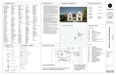
GENERAL NOTES GENERAL NOTES EXTERIOR PERSPECTIVE PROJECT DIRECTORY A.F.F. Above Finish Floor A.P. Access Panel ACOUS. Acoustical A.C.T. Acoustic Ceiling Tile A.C.P. Acoustic Ceiling Panel ADD'N Addition, Additional ADJ. Adjustable AGGR. Aggregate ALUM. Aluminum ALT. Alternate ANOD. Anodized APPR. Approved APPROX. Approximate ARCH. Architect, Architectural ASPH. Asphalt AUTO Automatic AUX. Auxiliary BKR. BD.Backer Board BSPL. Backsplash B.F. Barrier Free B. PL. Base Plate BSM'T Basement BM Beam BR'G Bearing B.M. Bench Mark BTW. Between BEV. Beveled BLK. Block BLK'G Blocking BD. Board B.O.S. Bottom of Slab BOT. Bottom B.U.R. Built-Up Roofing BLDG. Building CAB. Cabinet CPT. Carpet C.I.P. Cast-In-Place C.I. Cast Iron CDR. Cedar CLG. Ceiling C.H. Ceiling Height CEM. Cement or Cementitious C.P. Cement Plaster CTR. Center C/L Center Line C/C Center To Center CER. Ceramic C.T. Ceramic Tile C Channel CLO. Closet CLOS. Closure CLR. Clear C.M.U. Concrete Masonry Unit C.O. Clean Out COL. Column CW Cold Water COMP. Composite, Compacted CONC. Concrete CONN. Connect, Connection CONF. Conference CONTR. Contractor C.J. Control Joint CONSTR. Construction CONT. Continuous CORR. Corridor, Corrugated CTSK. Countersunk CNTR. Counter D.P. Dampproofing D.L. Dead Load DEMO. Demolition, Demolish DEPT. Department DET. Detail DIA. Diameter DIM. Dimension DIR. Directory, Direction D.W. Dishwasher DISP. Dispenser DISPO. Disposal DN. Down DR. Door D.O. Door Opening DBL. Double DS. Downspout DWR. Drawer DWG. Drawing D.S.P. Dry Standpipe D Dryer EA. Each E.F. Exhaust Fan E. East EL. Elevation ELEC.Electric, Electrical E.O.Electrical Outlet ELEV.Elevator ELIM.Eliminate EMER.Emergency ENAM.Enamel ENCL.Enclosure ENVIR.Environment EQ.Equal EQPT.Equipment EXC.Excavated EXP.Expansion EXP.B.Expansion Bolt E.J.Expansion Joint EXT.Exterior E.S.Exist Sign EXTG.Existing EXPO.Exposed FAB.Fabric F.A.Fire Alarm FAST.Fastener F.D.Floor Drain FDN.Foundation F.E.Fire Extinguisher F.F.Finished Floor F.H.C.Fire Hose Cabinet FIN.Finish FIXT.Fixture FLASH.Flashing FLR.Floor F.O. Finished Opeining F.O.C.Face of Concrete F.O.F.Face of Finish F.O.I.C.Furnished by Owner, Installed by Contractor F.O.M.Face of Masonry F.O.S.Face of Studs FPRF.Fireproof F.P.Floor Plan FT.Feet, Foot FTG.Footing FURN.Furnish, Furnished FURR.Furring FUT.Future G.A.Gauge GALV.Galvanized G.Gas G.C. General Contractor G.C.Gypsum Concrete GEN.General G.F.I.Ground Fault Interrupter GL.Glass GND.Ground G.R.Guard Rail GR.Grade GSM.Galvanized Sheet Metal GWB.Gypsum Wall Board GYP.Gypsum H.C.Handicapped H.R.Handrail HGR.Hanger HDWR.Hardware HDWD.Hardwood HD.Head HVAC.Heating, Ventilation & Air Conditioning HGT.Height H.P.High Point H.C.Hollow Core HCWD Hollow Core Wood Door H.M.Hollow Metal HORIZ.Horizontal H.B.Hose Bibb H.W.Hot Water H.W.H.Hot Water Heater HR.Hour HYD.Hydrant I.D. Inside Diameter (Dim.) INFO. Information IN. Inch or Inches INSUL. Insulation or Insulated INT. Interior JAN. Janitor J.S. Joint sealant JST. Joist JT. Joint K.O.P.Knock-out Panel KIT.Kitchen LAM.Laminate LAV.Lavatory L.H.Left Hand LKR.Locker L.P.Low Point L.S.Light Switch LT.Light LT. WT.Lightweight L.L.Liveload MACH.Machine MH.Manhole MFR.Manufacturer MARB. Marble MAS.Masonry M.O. Masonry Opening MAT'LMaterial MAX. Maximium MED.Medium MECH. Mechanical MEMB. Membrane MET./MTL.Metal or Metallic MEZZ.Mezzanine MICR. Microwave Oven MISC.Miscellaneous MIN. Minimum MIR. Mirror MTD.Mounted MUL.Mullion NOM. Nominal N. North N.I.C. Not In Contract N.T.S.Not To Scale NO. Number OFF.Office O.C.On Center O.H.Opposite Hand OPN'G.Opening OPP.Opposite O.D.Outside Diameter (Dim.) O.A.Overall O.H.Overhead PTD.Painted PR.Pair PNL.Panel P.H.Panic Hardware PTN.Partition PVM'T.Pavement PERF.Perforated PERIM.Perimeter PL.Plate PLAM.Plastic Laminate PLAS.Plaster PLYWD.Plywood PT.Point LBS.Pounds P.S.F.Pounds Per Square Foot P.S.L. Parallel Strand Lumber PWR.Power P.C.Pre-Cast P.T.Pressure Treated PROP.Property PVC.Polyvinyl Chloride Q.T.Quarry TIle RAD.Radius REF.Reference REFL.Reflected REFR.Refrigerator RGTR.Register REINF.Reinforced REQ'D.Required RESIL.Resilient RET.Retaining REV.Revised, Revision R.Riser R.D.Roof Drain R.D.O.Roof Drain Overflow RF'G.Roofing RM.Room R.O.Rough Opening RND.Round SAN.Sanitary SCHED.Schedule SCR.Scupper SLNT.Sealant SECT.Section S.South or Sink S.C.Solid Core S.D. Smoke Detector SHT'GSheathing SHT.Sheet SH.Shelf SHR.Shower SIM.Similar SNGL.Single SL.Slope SL.T.D.Slope to Drain S.Disp.Soap Dispenser SPK'RSpeaker SPEC.Specification SPSprinkler SQ.Square S.F.Square Feet (Foot) STAG'DStaggard SST.Stainless Steel STA.Station STN.Stain or Stained ST'D.Standard STL.Steel STOR.Storage STRUC.Structural SURF.Surface SUSP.Suspended SYM.Symmetrical TEL.Telephone T.V.Television TEMP.Temperature TEMP. GL.Tempered Glass THK.Thick T'HLD.Threshold T.O.C.Top of Concrete T.O.P.Top of Plate T.O.S.Top of Steel T.P.Top of Pavement T.O.W.Top of Wall T.P.H.Toilet Paper Holder T&G.Tounge & Groove T.B.Towel Bar T.C.Trash Compactor T.Tread TRTD.Treated TYP.Typical UNF.Unfinished U.O.N.Unless Otherwise Noted UR.Urinal VAR.Varies VERT.Vertical VEST.Vestibule V.I.F.Verify In Field V.P.Veneer Plaster V.C.T.Vinyl Composition Tile V.Volt WSCT.Wainscot W.C.Water Closet W.H.Water Heater WP. Waterproof(ing) W.R.Water Resistant WT.Weight W.W.M.Welded Wire Mesh W.West, Washer W/.With WDW.Window R.O.Rough Opening W/O.Without WD.Wood YD.Yard & And L Angle @ At # Pound or Number 1. 2. 3. 4. 5. 6. 7. 8. 9. 10. 11. 12. 13. 14. 15. 16. 17. The Contractor shall thoroughly review all Construction Documents including, but not limited to, drawings, notes, dimensions, schedules and specifications. The Contractor shall make a site visit and perform a detailed analysis and shall immediately bring any inconsistency, site layout problem, or any other request for clarification to the Architect for resolution prior to the delivery of any bid or initiation of work. Failure to do so shall cause the contractor to be ineligible for extras relating to such matters. These drawings are, in general, diagrammatic. Exact locations shall be determined by the Contractor from field measurements taken by Contractor's personnel. Actual arrangement of the work shall follow locations shown on the drawings within the constraints of existing equipment and construction, where such conditions exist. Drawing and notes to drawings are correlative and have equal authority and priority. Should there be discrepancies in themselves or between them, Contractor shall base bid pricing on the most expensive combination of quality and/or quantity of the work indicated. In the event of discrepancies, obtain clarification from Architect before continuing work. DO NOT SCALE THESE DRAWINGS. Immediately notify the Architect of any discrepancies or any other request for clarification. Verify all dimensions before ordering material and proceeding with the work. Minimum clearance dimensions indicated shall be maintained particularly at stairs, corridors and restrooms. Contractor to acquire all necessary permits prior to work. Contractor is responsible for the safety, actions, and conduct of his employees and his subcontractors' employees while in the project area, adjacent areas and in the building and its vicinity. Upon completion of work Contractor shall remove all debris from the site. Contractor shall submit reproducible shop drawings to Architect for Owner's, Architect's, and Engineer's Approval. All materials, finishes, manufactured items, and equipment shall be installed in full accordance with the supplier's or manufacturer's written recommendations or these documents, whichever is more restrictive. Notify the Architect of any variation in dimensions required for installation of equipment from those given in the Construction Documents before continuing the work. Every effort has been made on the part of the Architect to ensure local code compliance. It is the Contractor's responsibility to verify that the work conforms with all applicable codes and if discrepancies are noted to notify the Architect prior to work. Minor details not usually shown or specified but necessary for proper construction of any part of the work shall be included as if they were indicated on the drawings. Provide blocking as required for proper support of wall and ceiling mounted equipment or architectural elements. For all "match existing" notes Architect's intent is for Contractor to match existing profile and finish as closely as possible using available materials. If unable to match existing provide samples for alternate materials or methods for Architect's approval. Dissimilar metals to remain separated to avoid galvanic corrosion. All ceilings to be sheathed with 5/8" gypsum board unless otherwise noted. All interior paints, stains, and sealants to be low or no VOC rated. Contractor to notify architect and engineer(s) of any contradictory dimensions, specifications or other instructions that exist between the architectural, mechanical, electrical, plumbing, or other drawings that are included in the construction documents before continuing work VICINITY MAP (NTS) 1317 Westover Road SYMBOLS KEY MATERIALS LEGEND BUILDING KEY PLAN 1 View Name 1/8" = 1'-0" DRAWING TITLE WOOD, FINISH " 6 - ' 1 1 6 611' - 0" 6 1 0' - 6" " 0 - ' 0 1 6 " 6 9' - 0 6 " 0 9' - 0 6 " 6 - ' 8 0 6 0 COLUMN GRID 101 DOOR NUMBER WINDOW NUMBER Room name 101 ROOM NUMBER 1i PARTITION TYPE EXTERIOR ELEVATION MARKER 1 A101 DETAIL MARKER WALL SECTION MARKER DETAIL MARKER 1 A101 1 INTERIOR ELEVATION MARKER A101 1 A101 A101 1i 1 1 1 1 1 SPOT ELEVATION MARKER CONCRETE Name Elevation ELEVATION MARKER REVISION NUMBER WOOD, CONTINUOUS WOOD BLOCKING PLYWOOD, OSB, or MDF/MDO GYPSUM BOARD OR VENEER PLASTER ACOUSTIC CEILING PANEL BATT INSULATION RIGID INSULATION SEALANT, BACKING ROD STEEL or CAST IRON FIBER CEMENT BOARD CARPET ON PAD STONE CMU " 6 - ' 1 1 6 " 6 - ' 1 1 6 UP DN DW DN " 0 - 0' 1 6 UP " 6 - ' 9 0 6 6 1 1' - 6" 0 " - 6 1 1 ' " 6 - ' 0 1 6 610' - 0" " 6 - ' 9 0 6 " 0 - ' 9 0 6 " 6 - ' 8 0 6 LEGAL DESCRIPTION LOT 11 *& E 10 FT OF LOT 10 *& W 10 FT OF LOT 12 BLK 15 PEMBERTON HEIGHTS SEC 3 These drawings are property of the architect and may not be reproduced, distributed, published, or used in any way without written consent of the architect. Architect: Sanders Architecture 3706 Kerbey Lane Austin, TX 78731 (512) 482-9258 Owner: John and Liz Wright 1610 West Ave. Austin, TX 78701 Contractor: Miars Construction 2001 La Casa Austin, TX 78704 Structural Engineer: Structures, Inc. 6926 N. Lamar Blvd. Austin, TX 78752 (512) 499-0919 Landscape Architect: Civil Engineer: Geotechnical Engineer: Surveyor: SNS Engineering 12885 US Highway 183 North Suite 101-B Austin, TX 78750 (512) 335-3944 DRAWING INDEX Architectural Structural G0.00 G1.00 G1.01 G1.02 G1.03 G1.04 G2.01 A1.00 A1.01 A1.02 A1.03 A1.04 A3.01 A3.02 A3.03 S0.0 S0.1 S1.0 S1.1 S2.0 S2.1 S2.2 S2.3 S2.4 SL2.0 SL2.1 SL2.2 SL2.3 SL2.4 S3.0 S3.1 S3.2 S3.3 S4.0 S4.1 S5.0 S5.1 S5.2 S5.3 Cover Site Survey Proposed Site Plan Subchapter F Setback Compliance Subchapter F Setback Compliance Visitability Plan Door and Window Schedules Basement Floor Plan Ground Floor Plan Second Floor Plan Roof Plan Carport / Garage and Accessory Unit Plans Exterior Elevations Exterior Elevations Carport / Garage and Accessory Unit Elevations Structural Notes Structural Notes Basement Foundation Plan Garage and Carport Foundation Plan Ground Floor Foundation / Framing Plan Second Floor and Low Roof Framing Plan Roof Framing Plan Garage and Carport Framing Plan Efficiency Roof Framing Plan Ground Floor Lateral Bracing Plan Second Floor and Low Roof Lateral Bracing Plan Roof Lateral Bracing Plan Garage and Carport Lateral Bracing Plan Efficiency Lateral Bracing Plan Typical Foundation Details Foundation Details Foundation Details Foundation Details Typical Steel Framing Details Typical Steel Framing Details Typical Wood Framing Details Typical Wood Framing Details Typical Shear Wall Details Wood Details 07.31.2020 Copyright: These drawings are property of the architect and may not be reproduced, distributed, published, or used in any way without written consent of the architect. i e c n e d s e R d a o R r e v o t s e W d a o R r e v o t s e W 7 1 3 1 3 0 7 8 7 X T , n i t s u A CP-1 Construction Documents 07.31.2020 Drawn by: WP, EK Checked by: CS Revisions: Cover G0.00 07.31.2020 Copyright: These drawings are property of the architect and may not be reproduced, distributed, published, or used in any way without written consent of the architect. i e c n e d s e R d a o R r e v o t s e W d a o R r e v o t s e W 7 1 3 1 3 0 7 8 7 X T , n i t s u A CP-1 Construction Documents 07.31.2020 Drawn by: WP, EK Checked by: CS Revisions: Site Survey G1.00 611' - 0" 6 1 0' - 6" " 0 - ' 0 1 6 " 6 9' - 0 6 " 0 9' - 0 6 " 6 - ' 8 0 6 P O 5' P.U.E. per plat DN UP 97' - 1 1/4" O P O P O P O P " 6 - ' 1 1 6 W D GENERAL NOTES 1. Refer to setback compliance plan on sheet G1.03 for Subchapter F building area compliance and FAR and impervious cover calculations 2. Refer to building elevation drawings on sheet G1.02 for Subchapter F tent outline building area compliance 3. Refer to sheet G1.00 for existing survey information 4. Elevation 100'-0" as noted equals 613'-6" natural elevation above sea level. LEGAL DESCRIPTION LOT 11 *& E 10 FT OF LOT 10 *& W 10 FT OF LOT 12 BLK 15 PEMBERTON HEIGHTS SEC 3 Overhead power line, to be removed Existing power pole Overhead power line 07.31.2020 Copyright: These drawings are property of the architect and may not be reproduced, distributed, published, or used in any way without written consent of the architect. Existing tree, to be removed 9' - 2" Gravel O P 96' - 8" " 6 - ' 9 0 6 O P UP P O P O P O P O P O l t a p r e p . . E U P . ' 5 10' - 11" " 0 - ' 9 0 6 P O " 6 - ' 8 0 6 rear setback plane 10' - 0" i e c n e d s e R d a o R r e v o t s e W d a o R r e v o t s e W 7 1 3 1 3 0 7 8 7 X T , n i t s u A CP-1 Construction Documents 07.31.2020 Drawn by: WP, EK Checked by: CS Revisions: Proposed Site Plan G1.01 99' - 11 1/2" DN Wood Deck 96' - 8" " 0 - 0' 1 6 Pool 96' - 7 1/2" 610' - 0" " 6 - ' 0 1 6 " 6 - ' 9 0 6 " 6 - ' 1 1 6 l e n a p k c a b t e s e d s i " 2 / 1 0 - ' 5 97' - 9 1/2" 100' - 0" 98' - 6" 99' - 11 1/2" Stone walk Gravel " 6 - ' 1 1 6 I E V R D R E V O T S E W 7 1 3 1 e n i l y t r e p o r p 6 1 1' - 6" 97' - 6 1/2" 0 " " 0 - ' 5 6 1 1 ' l e n a p - k c a b t e s e d s i front setback plane 25' - 0" N 1 Poposed Site Plan 3/16" = 1'-0" Section C Section B Section A T.O. Ridge Main House 128' - 10" T.O. Ridge Efficiency 122' - 8 1/2" F.F. Efficiency 107' - 2 3/4" " 0 - ' 5 1 F.F. Garage/Carport 96' - 8" 4 5 . 0 0 ° e n i l k c a b e S t r a e R 10' - 0" Rear Setback T.O. Ridge Main House 128' - 10" l e n a P k c a b t e S t n o r F " 0 - ' 2 3 F.F. Main House 2nd Floor 110' - 6 3/4" F.F. Main House Ground Floor 100' - 0" High point Section C: 610' - 1 3/4" High point Section B: 611' - 2 1/4" High point Section A: 611' - 7 1/2" 4 Lot East Elevation - Height Restrictions and Setbacks 1/8" = 1'-0" Section A Section B Section C High point Section A: 611' - 7 1/2" High point Section B: 611' - 2 1/4" High point Section C: 610' - 1 3/4" 10' - 0" Rear Setback 3 Lot West Elevation - Height Restrictions and Setbacks 1/8" = 1'-0" l e n a P k c a b e S t t n o r F " 0 - ' 2 3 F.F. Main House 2nd Floor 110' - 6 3/4" F.F. Main House Ground Floor 100' - 0" 0° 5.0 4 e n i l k c a b e S t r a e R T.O. Ridge Efficiency 122' - 8 1/2" F.F. Efficiency 107' - 2 3/4" " 0 - ' 5 1 F.F. Garage/Carport 96' - 8" 07.31.2020 Copyright: These drawings are property of the architect and may not be reproduced, distributed, published, or used in any way without written consent of the architect. i e c n e d s e R d a o R r e v o t s e W d a o R r e v o t s e W 7 1 3 1 3 0 7 8 7 X T , n i t s u A T.O. Ridge Main House 128' - 10" 4 5 . 0 0 ° i e n L k c a b e S e d S t i " 0 - ' 2 3 " 0 - ' 5 1 F.F. Main House 2nd Floor 110' - 6 3/4" F.F. Main House Ground Floor 100' - 0" Maximum Building Height T.O. Ridge Main House 128' - 10" Maximum Building Height Subchapter F setback tent outline allowable building area: Section A Subchapter F setback tent outline allowable building area: Section B Subchapter F setback tent outline allowable building area: Section C T.O. Ridge Efficiency 122' - 8 1/2" 0° 5.0 4 i e n L k c a b e S e d S t i t n e m e s a E y t i l i t U c i l b u P 5' - 0" 10' - 0" F.F. Efficiency 107' - 2 3/4" " 0 - ' 5 1 F.F. Garage/Carport 96' - 8" F.F. Main House 2nd Floor 110' - 6 3/4" F.F. Main House Ground Floor 100' - 0" " 0 - ' 2 3 " 0 - ' 5 1 4 5 . 0 0 ° i e n L k c a b e S e d S t i t n e m e s a E y t i l i t U c i l b u P 5' - 0" 10' - 0" 5' - 0" Main House Beyond Efficiency Unit 2 Lot South Elevation - Height Restrictions and Setbacks 1/8" = 1'-0" 1 Lot North Elevation - Height Restrictions and Setbacks 1/8" = 1'-0" CP-1 Construction Documents 07.31.2020 Drawn by: WP, EK Checked by: CS Revisions: Subchapter F setback tent outline allowable building area: Section A Subchapter F setback tent outline allowable building area: Section B Subchapter F setback tent outline allowable building area: Section C 0° 5.0 4 i e n L k c a b e S e d S t i 5' - 0" " 0 - ' 5 1 Subchapter F Setback Compliance G1.02 SITE PROGRAM Site Area Allowable Impervious Area (45%) Allowable Floor-to-Area Ratio (40%) 9,625 SF 4,331 SF 3,850 SF Proposed Impervious Cover Area: Main House Building Accessory Unit Building Porches Driveway/Parking Sidewalks/Walkways Wood Deck, Stairs, and Ramp (50%) Exterior Stair Pool Coping Total Impervious Cover Proposed Floor-to-Area Ratio (F.A.R.) Main House Basement Main House First Floor Main House Second Floor Garage/Carport Accessory Unit F.A.R. Subtotal Parking Exemption Porch Exemption Basement Exemption F.A.R. Exemptions Total 2,025 SF 542 SF 264 SF 1,019 SF 83 SF 307/2 SF 92 SF 100 SF 4,279 SF 1,815 SF 2,289 SF 1,312 SF 542 SF 352 SF 6,310 SF -450 SF -264 SF -1,815 SF 2,529 SF Total F.A.R. (subtotal - exemptions) 3,781 SF i e n L y t r e p o r P Gravel 98' - 6" 100' - 0" 99' - 11 1/2" " 6 - ' 1 1 6 " 6 - ' 1 1 6 611' - 6" 25' - 0" Front Setback Section A Section B " 6 9' - 0 6 Section C " 0 9' - 0 6 " 6 - ' 8 0 6 " 0 - ' 5 k c a b t e S e d S i Property Line 5' P.U.E. Per Plat UP " 6 - ' 0 1 6 DN DW 99' - 11 1/2" DN Wood Deck 96' - 8" " 6 - ' 9 0 6 96' - 8" UP Pool " 6 - ' 9 0 6 " 0 - ' 9 0 6 " 6 - ' 8 0 6 Gravel i e n L y t r e p o r P t a P l r e P . . E U P . ' 5 10' - 0" Rear Setback " 0 - ' 5 k c a b t e S e d S i Section A High Point = 611'-7 1/2" Section C High Point = 610'-1 3/4" " 6 - ' 0 1 6 Section B High Point = 611'-2 1/4" Property Line N 1 Subchapter F Setback Compliance - Site Plan 1/8" = 1'-0" 07.31.2020 Copyright: These drawings are property of the architect and may not be reproduced, distributed, published, or used in any way without written consent of the architect. i e c n e d s e R d a o R r e v o t s e W d a o R r e v o t s e W 7 1 3 1 3 0 7 8 7 X T , n i t s u A CP-1 Construction Documents 07.31.2020 Drawn by: WP, EK Checked by: CS Revisions: Subchapter F Setback Compliance G1.03 VISITABILITY NOTES: 1. Light switches and environmental controls no higher than 48" above the interior floor level 2. Outlets and receptacles minimum 15" above interior floor level except for floor outlets 611' - 0" 6 1 0' - 6" " 0 - ' 0 1 6 " 6 9' - 0 6 " 0 9' - 0 6 " 6 - ' 8 0 6 97' - 11" UP 97' - 0" DN DRIVEWAY EXTERIOR ROUTE SLOPE 1:12 WITH GUARDRAIL GARAGE EXTERIOR ROUTE SLOPE <1:12 " 6 - ' 1 1 6 W D Gravel 100' - 0" 99' - 11 1/2" 99' - 11 1/2" VISITABLE ENTRANCE -DOOR 3'-0" X 9'-0" -VISITABLE NO-STEP ENTRY W/ MAX 1/2" BEVELED THRESHOLD -3' X 3' LANDING PROVIDED DN Wood Deck 32" CLEAR VISITABLE ROUTE VISITABLE BATHROOM -2'-8" X 7'-0" DOOR -2X6 BLOCKING CENTERLINE @ 34" A.F.F. -30" X 30" CLEAR FLOOR SPACE AS SHOWN " 0 - 0' 1 6 Pool 96' - 8" " 6 - ' 9 0 6 UP " 6 - ' 0 1 6 610' - 0" " 6 - ' 9 0 6 " 0 - ' 9 0 6 " 6 - ' 8 0 6 rear setback plane 10' - 0" Stone walk Gravel " 6 - ' 1 1 6 l e n a p k c a b t e s e d s i " 0 - ' 5 " 6 - ' 1 1 6 0 " " 0 - ' 5 6 1 1 ' l e n a p - k c a b t e s e d s i front setback plane 25' - 0" N 1 Visitability Plan 3/16" = 1'-0" I E V R D R E V O T S E W 7 1 3 1 e n i l y t r e p o r p 6 1 1' - 6" 07.31.2020 Copyright: These drawings are property of the architect and may not be reproduced, distributed, published, or used in any way without written consent of the architect. i e c n e d s e R d a o R r e v o t s e W d a o R r e v o t s e W 7 1 3 1 3 0 7 8 7 X T , n i t s u A CP-1 Construction Documents 07.31.2020 Drawn by: EK, WP Checked by: CS Revisions: Visitability Plan G1.04 Number Location Width Height Thickness Type Material Finish Type Finish Comments Mark Location Manufacturer Operation Width Height Rough Width Ext Finish Int Finish Comments Garage 9' - 8" 8' - 0" 1 3/4" Wood-clad 11' - 3" 12' - 9 3/4" 11' - 3 3/4" 11' - 3" Steel and glass window wall with swing door Trimless door W-118 Screen Porch Rehme Steel Windows & Fixed 9' - 0" 17' - 1" 9' - 0 3/4" 9' - 0" Steel and glass window wall with sliding door Kitchen 3' - 0" 8' - 0" 2" Aluminum/glass Aluminum/Wood Powder-coated 1-Wide Outswing VistaLuxe Entrace Door Basis of design: Kolbe VistaLuxe Exterior Door Media Room 2' - 8" 7' - 0" 1 3/4" Media Room 2' - 8" 7' - 0" 1 3/4" Dining Room 2' - 8" 7' - 0" 1 3/4" Pantry 3' - 0" 7' - 0" 1 3/4" Entry 3' - 0 3/4" 8' - 3 3/4" 2" Steel/glass Laundry 2' - 8" 7' - 0" 1 3/4" Wood Living Room 6' - 7 3/4" 9' - 0" 1 3/4" Steel/glass Master Bedroom 3' - 0" 7' - 0" 1 3/4" Master Bedroom 2' - 4" 7' - 0" 1 3/4" Master Bath 2' - 6" 7' - 0" 1 3/4" Master Closet 3' - 0" 7' - 0" 1 3/4" Powder 2' - 8" 7' - 0" 1 3/4" Closet Stairs 2' - 4" 7' - 0" 1 3/4" 3' - 0" 7' - 0" 1 3/4" Garage 3' - 0" 7' - 0" 2" Bedroom 2 2' - 8" 7' - 0" 1 3/4" 202a Bathroom 2 2' - 4" 7' - 0" 1 3/4" 202b Bathroom 2 2' - 4" 7' - 0" 1 3/4" Bedroom 4 2' - 8" 7' - 0" 1 3/4" Bathroom 4 2' - 4" 7' - 0" 1 3/4" Bedroom 3 2' - 4" 7' - 0" 1 3/4" Hall landing 2' - 8" 7' - 0" 1 3/4" Door and Frame Schedule Door Frame Material Painted, color TBD Painted, color TBD Painted, color TBD Painted, color TBD Painted, color TBD Powder-coated, color TBD Painted, color TBD Painted, color TBD Painted, color TBD Painted, color TBD Painted, color TBD Painted, color TBD Painted, color TBD Painted, color TBD Painted, color TBD Powder-coated, color TBD Powder-coated, color TBD Painted, color TBD Painted, color TBD Painted, color TBD Painted, color TBD Painted, color TBD Painted, color TBD Painted, color TBD Powder-coated, color TBD Powder-coated, color TBD Painted, color TBD Powder-coated, color TBD F4 F4 F1 F7 F7 F3 F4 F2 F4 D7 F4 F7 F7 F4 F4 F9 F6 F5 F4 D7 D7 F4 D7 D7 F4 F8 F3 F7 F3 Wood Wood Steel Wood Wood Wood Steel Wood Wood Wood Wood Wood Wood Wood Wood Metal Wood Wood Wood Wood Wood Wood Wood Wood Painted, color TBD Painted, color TBD Painted, color TBD Painted, color TBD Painted, color TBD color TBD Painted, color TBD Painted, color TBD Painted, color TBD Painted, color TBD Painted, color TBD Painted, color TBD Painted, color TBD Painted, color TBD Painted, color TBD Powder-coated color TBD Powder-coated color TBD Painted, color TBD Painted, color TBD Painted, color TBD Painted, color TBD Painted, color TBD Painted, color TBD Painted, color TBD color TBD color TBD Painted, color TBD color TBD Wood Wood Wood Wood Wood Wood Wood Wood Wood Wood Wood Wood Wood Wood Wood Wood Wood Wood Wood D4 D4 D1 D7 D7 D8 D4 D2 D4 D7 D4 D7 D7 D4 D4 D6 D9 D4 D7 D7 D4 D7 D7 D4 D8 D3 D7 D3 001 002 100 101 102 103 104 105 106 107 108 109 110 111 112 113 114 201 204 205 206 207 208 209 210 211 Fixed 4' - 0" 4' - 6" 4' - 0 3/4" 4' - 6 1/2" 8' - 0" Butt glazed corner window Window Schedule Rough Height Head Height W-001 Media Room Casement 4' - 0" 4' - 0" 4' - 0 3/4" 4' - 0 3/4" 7' - 0" W-101 Master Bedroom W-102 Master Bedroom W-103 Master Bedroom W-104 Master Bath W-105 Master Bath W-106 Master Bath Kolbe & Kolbe Millwork Co., Inc. Kolbe & Kolbe Millwork Co., Inc. Kolbe & Kolbe Millwork Co., Inc. Kolbe & Kolbe Millwork Co., Inc. Kolbe & Kolbe Millwork Co., Inc. Kolbe & Kolbe Millwork Co., Inc. Kolbe & Kolbe Millwork Co., Inc. Fixed Fixed Fixed Fixed Fixed 10' - 0" 7' - 0" 10' - 0 1/2" 7' - 0 1/2" 8' - 9" 2' - 0" 3' - 0" 2' - 0 3/4" 3' - 0 3/4" 8' - 0" 2' - 0" 3' - 0" 2' - 0 3/4" 3' - 0 3/4" 8' - 0" Casement 2' - 0" 3' - 0" 2' - 0 1/2" 3' - 0 1/2" 7' - 0" 2' - 0" 3' - 0" 2' - 0 3/4" 3' - 0 3/4" 7' - 0" 2' - 0" 3' - 0" 2' - 0 3/4" 3' - 0 3/4" 8' - 0" W-107 Master Closet Kolbe & Kolbe Millwork Co., Fixed 2' - 0" 3' - 0" 2' - 0 3/4" 3' - 0 3/4" 7' - 0" W-108 Master Closet Kolbe & Kolbe Millwork Co., Fixed 7' - 0" 8' - 0" 7' - 0 1/2" 8' - 0 1/2" 9' - 0" W-109 Dining Room Kolbe & Kolbe Millwork Co., Fixed 7' - 0" 8' - 0" 7' - 0 1/2" 8' - 0 1/2" 9' - 0" W-110 Dining Room Kolbe & Kolbe Millwork Co., Casement 3' - 6" 8' - 0" 3' - 6 1/2" 8' - 0 1/2" 9' - 0" Fixed Fixed Fixed Fixed Fixed Fixed Fixed Fixed Fixed Inc. Inc. Inc. Inc. Kolbe & Kolbe Millwork Co., Inc. Kolbe & Kolbe Millwork Co., Inc. Kolbe & Kolbe Millwork Co., Inc. Kolbe & Kolbe Millwork Co., Inc. Doors Rehme Steel Windows & Doors Kolbe & Kolbe Millwork Co., Inc. Kolbe & Kolbe Millwork Co., Inc. Kolbe & Kolbe Millwork Co., Inc. Kolbe & Kolbe Millwork Co., Inc. Kolbe & Kolbe Millwork Co., Inc. Kolbe & Kolbe Millwork Co., Inc. Kolbe & Kolbe Millwork Co., Inc. Kolbe & Kolbe Millwork Co., Inc. Kolbe & Kolbe Millwork Co., Inc. Kolbe & Kolbe Millwork Co., Inc. Kolbe & Kolbe Millwork Co., Inc. Kolbe & Kolbe Millwork Co., Inc. Kolbe & Kolbe Millwork Co., Inc. Kolbe & Kolbe Millwork Co., Inc. Kolbe & Kolbe Millwork Co., Inc. Kolbe & Kolbe Millwork Co., Inc. Inc. W-114 Laundry W-115 Kitchen W-116 Kitchen W-117 Pantry W-119 Entry W-201 Bedroom 3 W-202 Bedroom 3 W-203 Bedroom 3 W-204 Bedroom 3 W-205 Bedroom 3 W-206 Bathroom 3 W-207 Bathroom 4 W-208 Bedroom 4 W-209 Bedroom 4 W-210 Bedroom 4 W-211 Bedroom 4 W-213 Bedroom 2 W-213 Bedroom 2 W-215 WC W-216 Bathroom 2 W-217 Hall landing Casement 7' - 0" 4' - 6" 7' - 0 1/2" 4' - 6 1/2" 8' - 0" 4' - 0" 4' - 6" 4' - 0 1/2" 4' - 6 1/2" 8' - 0" 4' - 0" 4' - 6" 4' - 0 1/2" 4' - 6 1/2" 8' - 0" 17' - 0 1/4" 12' - 9" 2' - 0" 3' - 0" 2' - 0 3/4" 3' - 0 3/4" 7' - 0 3/4" Clad Wood, color 2' - 6" 2' - 6" 2' - 0" 2' - 6 1/2" 7' - 0 3/4" 7' - 0 3/4" 3' - 0" 2' - 0 3/4" 2' - 6 1/2" 7' - 1 1/4" 7' - 0 3/4" Clad Wood, color 7' - 1 1/4" 7' - 0 3/4" Clad Wood, color 3' - 0 3/4" 7' - 0 3/4" Clad Wood, color 2' - 0" 3' - 0" 2' - 0 3/4" 3' - 0 3/4" 7' - 0 3/4" Clad Wood, color Casement 2' - 0" 3' - 0" 2' - 0 1/2" 3' - 0 1/2" 7' - 0 3/4" Clad Wood, color Casement 2' - 0" 3' - 0" 2' - 0 1/2" 3' - 0 1/2" 7' - 0 3/4" Clad Wood, color 2' - 0" 3' - 0" 2' - 0 3/4" 3' - 0 3/4" 7' - 0 3/4" Clad Wood, color 2' - 0" 3' - 0" 2' - 0 3/4" 3' - 0 3/4" 7' - 0 3/4" Clad Wood, color 7' - 0" 7' - 0" 7' - 0 1/2" 7' - 0 1/2" 9' - 11 1/4" Clad Wood, color Fixed 7' - 0" 6' - 0" 7' - 0 1/2" 6' - 0 1/2" 6' - 11 1/4" Clad Wood, color Casement 2' - 0" 3' - 0" 2' - 0 1/2" 3' - 0 1/2" 5' - 4" Casement 2' - 0" 3' - 0" 2' - 0 1/2" 3' - 0 1/2" 7' - 0" Casement 2' - 0" 3' - 0" 2' - 0 1/2" 3' - 0 1/2" 7' - 0" Clad Wood, color TBD Clad Wood, color TBD Clad Wood, color TBD Clad Wood, color TBD Clad Wood, color TBD Clad Wood, color TBD Clad Wood, color TBD Clad Wood, color TBD Clad Wood, color TBD Clad Wood, color TBD Clad Wood, color TBD Clad Wood, color TBD Clad Wood, color TBD Clad Wood, color TBD Clad Wood, color TBD Painted Steel, color TBD Painted Steel, color TBD TBD TBD TBD TBD TBD TBD TBD TBD TBD TBD Clad Wood, color TBD TBD Clad Wood, color TBD Clad Wood, color TBD Clad Wood, color TBD Painted Steel, color TBD Clad Wood, color TBD Clad Wood, color TBD Clad Wood, color TBD TBD TBD Painted, color TBD Painted, color TBD Painted, color TBD Painted, color TBD Painted, color TBD Painted, color TBD Painted, color TBD Painted, color TBD Painted, color TBD Painted, color TBD Painted, color TBD Painted, color TBD Painted, color TBD Painted, color TBD Painted, color TBD Painted Steel, color TBD Painted Steel, color TBD Painted, color TBD Painted, color TBD Painted, color TBD Painted, color TBD Painted, color TBD Painted, color TBD Painted, color TBD Painted, color TBD Painted, color TBD Painted, color TBD Painted, color TBD Painted, color TBD Painted, color TBD Painted, color TBD Painted, color TBD Painted, color TBD Painted, color TBD Painted, color TBD Painted, color TBD TBD TBD Dormer 4' - 0" 6' - 3" 6' - 3 1/2" 4' - 0 1/2" 10' - 6" Custom dormer window, butt glazed corners W-218 Accessory Unit Kolbe & Kolbe Millwork Co., Fixed 7' - 0" 4' - 0" 7' - 0 1/2" 4' - 0 1/2" 7' - 0" W-219 Accessory Unit Kolbe & Kolbe Millwork Co., Fixed 10' - 0" 7' - 0" 10' - 0 1/2" 7' - 0 1/2" 7' - 0" W-220 Bathroom 2' - 0" 3' - 0" 2' - 0 3/4" 3' - 0 3/4" 7' - 0" Inc. Kolbe & Kolbe Millwork Co., Inc. TBD TBD Fixed Fixed Fixed W-301 W-302 2' - 0" 2' - 0" 4' - 0" 2' - 0 1/2" 4' - 0" 2' - 0 1/2" 4' - 0 1/2" 4' - 0 1/2" Skylight at Bedroom 2 Skylight at Accessory Unit Bedroom 3 6' - 0" 7' - 0 3/4" Accessory Unit 3' - 0" 7' - 0" 2" 2" Aluminum/glass Aluminum/glass Bathroom 2' - 8" 7' - 0" 1 3/4" Wood Aluminum/Wood Powder-coated 1-Wide Outswing VistaLuxe Entrace Door Basis of design: Kolbe VistaLuxe Exterior Door Basis of design: Kolbe VistaLuxe Exterior Door Aluminum/Wood Powder-coated 1-Wide Outswing VistaLuxe Entrace Door Basis of design: Kolbe VistaLuxe Exterior Door Terrace 3' - 0" 7' - 0" 2" Aluminum/glass Aluminum/Wood Powder-coated 1-Wide Outswing VistaLuxe Entrace Door Basis of design: Kolbe VistaLuxe Exterior Door Casement 2' - 0" 3' - 0" 2' - 0 1/2" 3' - 0 1/2" 6' - 0" 07.31.2020 Copyright: These drawings are property of the architect and may not be reproduced, distributed, published, or used in any way without written consent of the architect. i e c n e d s e R d a o R r e v o t s e W d a o R r e v o t s e W 7 1 3 1 3 0 7 8 7 X T , n i t s u A CP-1 Construction Documents 07.31.2020 Drawn by: WP, EK Checked by: CS Revisions: Door and Window Schedules G2.01 Dashed line of extents of first floor, above 16' - 9 1/2" Egress ladder " 4 1 / 0 - ' 2 " 4 3 / 6 - ' 1 Q E Q E F.O.F. W-001 3' - 3" CLR F.O.F. S R L C " 0 - ' 3 UP " 8 - ' 1 r o o d 2 0 0 S 6' - 0 3/4" 8' - 3 3/4" 2' - 2" 4' - 3" 1' - 0 1/2" sink Storage/MEP 002 8'-10" CLG Basement F.F. 89' - 7 1/4" Media Room 000 8'-10" CLG . . F O F . EQ EQ " 4 3 / 6 - ' 4 Q E t e l i o t Q E 5' - 1 1/4" shower Media Bath 001 8'-10" CLG F.O.F. 001 EQ S EQ sink/ door 4' - 2" 7' - 4 1/4" 90' - 1 1/4" 90' - 7 1/4" " 4 3 / 5 - ' 7 " 0 - ' 1 " 2 1 / 1 1 - ' 7 1 A B C D E F " 2 1 / 9 - ' 3 " 2 - ' 7 " 4 1 / 6 - ' 8 1 " 4 - ' 0 1 16' - 9 1/2" 14' - 8 1/2" 3' - 9" 10' - 4 1/2" 1 2 3 4 5 N 1 Basement Floor Plan 1/4" = 1'-0" GENERAL PLAN NOTES: 1. Elevation 100'-0" as noted equals 613'-6" natural elevation above sea level. 2. Refer to G2.01 for wall types. 3. All dimensions to face of framing unless otherwise specified. 4. Maintain R13 minimum insulation for exterior walls. All insulation to be either labeled or the installed R-values provided. All insulation to be installed per manufacturer's instructions. All air barriers and thermal barriers to be installed per manufacturer's instructions. 5. Maintain R38 minimum insulation for attics and roofs, typ. All insulation to be either labeled or the installed R-values provided. All insulation to be installed per manufacturer's instructions. All air barriers and thermal barriers to be installed per manufacturer's instructions. Attic spaces to be unvented with air-impermeable insulation at underside of roof sheathing. 6. Provide carbon monoxide detectors in vicinity of sleeping rooms in accordance with IRC R315. 7. Provide smoke detector system (hardwired, interconnected, battery back-up) at each sleeping room and vicinity in accordance with IRC R314. 8. Residential fire sprinkler system to be designed and installed in accordance with the latest version oft he Nation Fire Protection Association (NFPA) 13D. SUBMIT SPRINKLER PLANS TO ARCHITECT, ALLOWING REASONABLE TIME FOR REVIEW BEFORE INSTALLATION OR ANY REQUIRED AGENCY APPROVAL. Legend: S Wall Mounted Smoke Alarm/ Carbon Monoxide Detector 07.31.2020 Copyright: These drawings are property of the architect and may not be reproduced, distributed, published, or used in any way without written consent of the architect. i e c n e d s e R d a o R r e v o t s e W d a o R r e v o t s e W 7 1 3 1 3 0 7 8 7 X T , n i t s u A CP-1 Construction Documents 07.31.2020 Drawn by: WP, EK Checked by: CS Revisions: Basement Floor Plan A1.00 GENERAL PLAN NOTES: 1. Elevation 100'-0" as noted equals 613'-6" natural elevation above sea level. 2. Refer to G2.01 for wall types. 3. All dimensions to face of framing unless otherwise specified. 4. Maintain R13 minimum insulation for exterior walls. All insulation to be either labeled or the installed R-values provided. All insulation to be installed per manufacturer's instructions. All air barriers and thermal barriers to be installed per manufacturer's instructions. 5. Maintain R38 minimum insulation for attics and roofs, typ. All insulation to be either labeled or the installed R-values provided. All insulation to be installed per manufacturer's instructions. All air barriers and thermal barriers to be installed per manufacturer's instructions. Attic spaces to be unvented with air-impermeable insulation at underside of roof sheathing. 6. Provide carbon monoxide detectors in vicinity of sleeping rooms in accordance with IRC R315. 7. Provide smoke detector system (hardwired, interconnected, battery back-up) at each sleeping room and vicinity in accordance with IRC R314. 8. Residential fire sprinkler system to be designed and installed in accordance with the latest version oft he Nation Fire Protection Association (NFPA) 13D. SUBMIT SPRINKLER PLANS TO ARCHITECT, ALLOWING REASONABLE TIME FOR REVIEW BEFORE INSTALLATION OR ANY REQUIRED AGENCY APPROVAL. Legend: S Wall Mounted Smoke Alarm/ Carbon Monoxide Detector EQ EQ DS DS DS EQ EQ 5' - 11 1/2" 15' - 7 3/4" doors 5' - 11 3/4" A3.01 1 Grade @ gravel 98' - 6" UP T.O. Porch 99' - 11 1/2" W-119 100 Level 1 F.F. 100' - 0" Entry 100 9'-0" CLG R L C " 0 - ' 3 UP 111 112 Stairs 112 l l a w h / t r a e h / l e c a p e r i f Living Room 105 9'-0" CLG W-108 109 k n s i k n s i window Master Closet 109 9'-0" CLG 6' - 0 1/4" EQ EQ 6' - 1 1/2" W-106 " 0 - ' 1 " 7 - ' 3 " 7 - ' 3 Q E Q E / w o d n w i / t e l i o t r o o d 108 2' - 8 1/2" b u t Master Bath 108 9'-0" CLG door EQ EQ r e w o h s " 4 3 / 0 - ' 3 " 6 - ' 3 " 4 - ' 4 " 5 - ' 3 Q E Q E " 2 - ' 3 F.O.F. t e l i o t " 7 - ' 1 " 0 - ' 3 Powder 110 9'-0" CLG 110 Closet 111 8'-0" CLG 6' - 1 1/2" 2' - 9 1/4" 1' - 4 3/4" Q E " 8 " 4 3 / 8 - ' 3 " 8 3' - 9 3/4" S S 106 107 2' - 5 3/4" Q E Master Bedroom 107 9'-0" CLG " 2 / 1 4 - ' 1 1 T.O. Porch 99' - 11 1/2" Screen Porch 106 vaulted T.O. Deck 99' - 11 1/2" W-101 DN W-109 Dining Room 101 101 102 Pantry 102 9'-0" CLG Kitchen 103 9'-0" CLG DW 1' - 7 1/2" 3' - 10 1/4" 3' - 5 1/2" 103 W D Laundry 104 9'-0" CLG W-110 Q E Q E W-117 W-115 W-116 DN " 2 1 / 5 - ' 7 " 4 3 / 6 - ' 3 " 4 3 / 8 - ' 3 " 4 1 / 7 - ' 5 " 8 - ' 5 1 DS W-114 UP W-118 REF 104 16' - 9 1/2" 14' - 8 1/2" 3' - 9" 10' - 4 1/2" 1 1 Ground Floor Plan 1/4" = 1'-0" 2 2 A3.02 3 4 5 DS W-107 W-105 W-104 DS W-103 W-102 " 4 1 / 6 - ' 2 " 8 " 4 1 / 1 1 - ' 2 " 4 3 / 6 - ' 0 1 " 2 1 / 5 - ' 3 " 4 3 / 7 - ' 2 " 8 - ' 5 " 4 3 / 6 - ' 1 " 4 / 1 0 - ' 2 " 2 1 / 3 - ' 0 1 " 2 1 / 9 - ' 3 " 2 - ' 7 " 4 1 / 6 - ' 8 1 " 4 - ' 0 1 " 6 - ' 1 A B C D E F G N A3.01 2 1 A3.02 07.31.2020 Copyright: These drawings are property of the architect and may not be reproduced, distributed, published, or used in any way without written consent of the architect. i e c n e d s e R d a o R r e v o t s e W d a o R r e v o t s e W 7 1 3 1 3 0 7 8 7 X T , n i t s u A CP-1 Construction Documents 07.31.2020 Drawn by: WP, EK Checked by: CS Revisions: Ground Floor Plan A1.01 GENERAL PLAN NOTES: 1. Elevation 100'-0" as noted equals 613'-6" natural elevation above sea level. 2. Refer to G2.01 for wall types. 3. All dimensions to face of framing unless otherwise specified. 4. Maintain R13 minimum insulation for exterior walls. All insulation to be either labeled or the installed R-values provided. All insulation to be installed per manufacturer's instructions. All air barriers and thermal barriers to be installed per manufacturer's instructions. 5. Maintain R38 minimum insulation for attics and roofs, typ. All insulation to be either labeled or the installed R-values provided. All insulation to be installed per manufacturer's instructions. All air barriers and thermal barriers to be installed per manufacturer's instructions. Attic spaces to be unvented with air-impermeable insulation at underside of roof sheathing. 6. Provide carbon monoxide detectors in vicinity of sleeping rooms in accordance with IRC R315. 7. Provide smoke detector system (hardwired, interconnected, battery back-up) at each sleeping room and vicinity in accordance with IRC R314. 8. Residential fire sprinkler system to be designed and installed in accordance with the latest version oft he Nation Fire Protection Association (NFPA) 13D. SUBMIT SPRINKLER PLANS TO ARCHITECT, ALLOWING REASONABLE TIME FOR REVIEW BEFORE INSTALLATION OR ANY REQUIRED AGENCY APPROVAL. Legend: S Wall Mounted Smoke Alarm/ Carbon Monoxide Detector 1 2 3 4 5 16' - 9 1/2" 14' - 8 1/2" 3' - 9" 10' - 4 1/2" A3.01 1 EQ window EQ W-210 Bedroom 4 204 vaulted 5' - 4 3/4" 3' - 2 1/4" 205 EQ EQ Bathroom 4 205 9'-0" CLG Q F.O.F. E Q E W-207 1' - 2 3/4" 4' - 7 1/4" sink 2' - 9" S S 204 toilet doors 1' - 7" 1' - 7" 3' - 1 3/4" F.O.F. " 4 1 / 6 - ' 2 DS W-211 " 4 1 / 6 - ' 2 DS W-213 : 2 1 5 2 . 0 DS EQ EQ window EQ window EQ W-213 Bedroom 2 201 vaulted 6' - 7 1/4" 2' - 0 3/4" 5' - 3" 3' - 4 3/4" 1' - 6" 2' - 4" 2' - 2 3/4" 2' - 11 1/4" Bathroom 3 sink toilet 206 9'-0" CLG 207 S b u t Q E Q E 3' - 5" 206 " 4 3 / 4 - ' 1 Bedroom 3 207 vaulted " 2 1 / 8 - ' 1 r o o d " 4 3 / 0 - ' 3 Second Floor F.F. 110' - 6 3/4" 201 Hall landing S S 200 7' - 6 1/2" EQ EQ window 6' - 2 3/4" 3' - 5 3/4" door / sink 202a EQ EQ shower head " 4 1 / 0 - ' 3 " 4 3 / 2 - ' 2 202b EQ EQ toilet/door W-215 WC 203 9'-0" CLG W-216 Bathroom 2 202 9'-0" CLG 0.25:12 2' - 3 3/4" 5' - 7 1/2" 5' - 7 1/2" 2' - 3 3/4" window door 208 window W-201 W-217 Steel plate awning, below R L C " 0 - ' 3 DN " 4 3 / 4 - ' 3 " 4 1 / 2 - ' 2 " 4 3 / 4 - ' 8 w o d n w i " 4 3 / 1 - ' 5 " 0 - ' 3 Line of eave, above w o d n w i w o d n w i " 9 - ' 7 " 4 1 / 8 - ' 3 " 2 1 / 4 - ' 3 " 4 3 / 0 - ' 1 " 2 1 / 3 - ' 1 " 4 3 / 2 - ' 1 W-203 W-202 Terrace 208 RD slope 2% typ. @ membrane roof DS 10' - 8 1/4" 3' - 3 3/4" 4' - 8 3/4" 8' - 7 3/4" A B C D E F G w o d n w i w o d n w i DS W-209 W-208 " 4 1 / 6 - ' 2 " 2 1 / 5 - ' 1 Q E w o d n w i Q E W-206 W-205 w o d n w i W-204 DS " 4 1 / 1 - ' 1 " 2 1 / 2 - ' 1 " 4 3 / 4 - ' 3 " 4 3 / 9 - ' 1 " 6 - ' 8 " 4 3 / 0 - ' 2 " 4 / 1 9 - ' 1 1 " 2 1 / 3 - ' 0 1 " 2 1 / 9 - ' 3 " 2 - ' 7 " 4 1 / 6 - ' 8 1 " 4 - ' 0 1 " 6 - ' 1 A3.01 2 1 A3.02 N 1 Second Floor Plan 1/4" = 1'-0" 2 A3.02 07.31.2020 Copyright: These drawings are property of the architect and may not be reproduced, distributed, published, or used in any way without written consent of the architect. i e c n e d s e R d a o R r e v o t s e W d a o R r e v o t s e W 7 1 3 1 3 0 7 8 7 X T , n i t s u A CP-1 Construction Documents 07.31.2020 Drawn by: WP, EK Checked by: CS Revisions: Second Floor Plan A1.02 1 2 3 4 5 16' - 9 1/2" 14' - 8 1/2" 3' - 9" 10' - 4 1/2" Gutter Gutter DS DS Steel plate awning DS Slope 12:12 Slope 12:12 e p o S l : 2 1 5 2 . 0 Slope 12:12 Slope 12:12 Gutter DS " 2 1 / 5 - ' 2 t h g i l y k s W-301 e p o S l : 2 1 0 1 A3.01 2 e p o S l 2 1 : 3 e p o S l : 2 1 0 1 Exhaust stack chimney 1 A3.02 Steel plate awning Slate roof, typ. RD slope 2% typ. @ membrane roof e p o S l 2 1 : 2 DS A B C D E F G " 2 1 / 3 - ' 0 1 " 2 1 / 9 - ' 3 " 2 - ' 7 " 4 1 / 6 - ' 8 1 " 4 - ' 0 1 " 6 - ' 1 Exhaust stack chimney Chimney DS Wood deck over TPO roof N 1 Roof Plan 1/4" = 1'-0" GENERAL PLAN NOTES: 1. Elevation 100'-0" as noted equals 613'-6" natural elevation above sea level. 2. Refer to G2.01 for wall types. 3. All dimensions to face of framing unless otherwise specified. 4. Maintain R13 minimum insulation for exterior walls. All insulation to be either labeled or the installed R-values provided. All insulation to be installed per manufacturer's instructions. All air barriers and thermal barriers to be installed per manufacturer's instructions. 5. Maintain R38 minimum insulation for attics and roofs, typ. All insulation to be either labeled or the installed R-values provided. All insulation to be installed per manufacturer's instructions. All air barriers and thermal barriers to be installed per manufacturer's instructions. Attic spaces to be unvented with air-impermeable insulation at underside of roof sheathing. 6. Provide carbon monoxide detectors in vicinity of sleeping rooms in accordance with IRC R315. 7. Provide smoke detector system (hardwired, interconnected, battery back-up) at each sleeping room and vicinity in accordance with IRC R314. 8. Residential fire sprinkler system to be designed and installed in accordance with the latest version oft he Nation Fire Protection Association (NFPA) 13D. SUBMIT SPRINKLER PLANS TO ARCHITECT, ALLOWING REASONABLE TIME FOR REVIEW BEFORE INSTALLATION OR ANY REQUIRED AGENCY APPROVAL. 07.31.2020 Copyright: These drawings are property of the architect and may not be reproduced, distributed, published, or used in any way without written consent of the architect. i e c n e d s e R d a o R r e v o t s e W d a o R r e v o t s e W 7 1 3 1 3 0 7 8 7 X T , n i t s u A CP-1 Construction Documents 07.31.2020 Drawn by: WP, EK Checked by: CS Revisions: Roof Plan A1.03 Legend: S Wall Mounted Smoke Alarm/ Carbon Monoxide Detector GENERAL PLAN NOTES: 1. Elevation 100'-0" as noted equals 613'-6" natural elevation above sea level. 2. Refer to G2.01 for wall types. 3. All dimensions to face of framing unless otherwise specified. 4. Maintain R13 minimum insulation for exterior walls. All insulation to be either labeled or the installed R-values provided. All insulation to be installed per manufacturer's instructions. All air barriers and thermal barriers to be installed per manufacturer's instructions. 5. Maintain R38 minimum insulation for attics and roofs, typ. All insulation to be either labeled or the installed R-values provided. All insulation to be installed per manufacturer's instructions. All air barriers and thermal barriers to be installed per manufacturer's instructions. Attic spaces to be unvented with air-impermeable insulation at underside of roof sheathing. 6. Provide carbon monoxide detectors in vicinity of sleeping rooms in accordance with IRC R315. 7. Provide smoke detector system (hardwired, interconnected, battery back-up) at each sleeping room and vicinity in accordance with IRC R314. 8. Residential fire sprinkler system to be designed and installed in accordance with the latest version oft he Nation Fire Protection Association (NFPA) 13D. SUBMIT SPRINKLER PLANS TO ARCHITECT, ALLOWING REASONABLE TIME FOR REVIEW BEFORE INSTALLATION OR ANY REQUIRED AGENCY APPROVAL. Zinc half round gutter, typ Slope 12:12 Slope 12:12 t h g i l y k s W-302 " 4 - ' 5 DS A3.03 2 DS RD A3.03 2 2' - 0" Carport F.F. 96' - 8" Garage F.F. 96' - 8" 2' - 5 1/4" door 113 Carport 113 Q E Q E DS H " 4 1 / 9 - ' 4 2 A3.03 1 " 2 1 / 7 - ' 2 1 " 4 3 / 1 - ' 2 1 N I " 4 / 3 4 - ' 3 UP H I " 4 1 / 9 - ' 4 2 " 4 / 3 4 - ' 3 A3.03 2 DS EQ EQ W-219 Accessory Unit 209 W-218 window Accessory Unit F.F. 107' - 2 3/4" S 210 sink 1' - 4" Terrace 211 T.O. Deck 107' - 2 1/4" 211 " 4 1 / 3 - ' 9 " 1 1 - ' 1 " 4 1 / 1 1 - ' 6 209 DS W-220 DN R L C " 4 / 1 0 - ' 3 4' - 0" 4' - 6 1/2" EQ EQ 7' - 5" window/toilet 13' - 6 1/2" door 3 A3.03 6 N H " 4 / 1 9 - ' 4 2 I 3 Garage and Carport Floor Plan 1/4" = 1'-0" 2 Guest House Floor Plan 1/4" = 1'-0" 7' - 5" 13' - 6 1/2" 3 A3.03 6 7 8 7 8 6 7 8 7' - 5" 13' - 6 1/2" 3 A3.03 N 1 Guest House Roof Plan 1/4" = 1'-0" 4 A3.03 A3.03 1 4 A3.03 A3.03 1 4 A3.03 Garage 114 114 EQ EQ Bathroom 210 " 0 - ' 2 r o o d slope 2% typ. @ membrane roof RD 07.31.2020 Copyright: These drawings are property of the architect and may not be reproduced, distributed, published, or used in any way without written consent of the architect. i e c n e d s e R d a o R r e v o t s e W d a o R r e v o t s e W 7 1 3 1 3 0 7 8 7 X T , n i t s u A CP-1 Construction Documents 07.31.2020 Drawn by: WP, EK Checked by: CS Revisions: Carport / Garage and Accessory Unit Plans A1.04 5 4 3 2 1 12 12 W-213 W-109 Steel guardrail, beyond 100 W-119 12 12 +1.5" -2" 0" W-210 W-108 A B C D E F G T.O. Ridge Main House 128' - 10" Slate roof T.O. Plate 2nd Floor 119' - 8 1/2" Zinc gutters and downspouts, typ. Steel windows and doors Brick surround at bay window F.F. Main House 2nd Floor 110' - 6 3/4" F.F. Main House Ground Floor 100' - 0" 1 North Elevation 1/4" = 1'-0" T.O. Ridge Main House 128' - 10" T.O. Plate 2nd Floor 119' - 8 1/2" F.F. Main House 2nd Floor 110' - 6 3/4" F.F. Main House Ground Floor 100' - 0" 2 West Elevation 1/4" = 1'-0" Zinc-clad chimney, beyond Brick Brick soldier course corbel (+1.5") Brick header course corbel (+1.5") Zinc chimney cap, beyond Brick chimney, beyond Aluminum-clad wood windows, typ. Brick corbel at chimney, beyond Brick soldier plinth course (+1.5") Zinc-clad chimney, beyond Zinc chimney cap Slate roof Brick Zinc gutters and downspouts, typ. Brick chimney Steel guardrail Brick header reveal (+1.5") Aluminum-clad wood windows, typ. Brick sill, typ. (+1.5") 07.31.2020 Copyright: These drawings are property of the architect and may not be reproduced, distributed, published, or used in any way without written consent of the architect. i e c n e d s e R d a o R r e v o t s e W d a o R r e v o t s e W 7 1 3 1 3 0 7 8 7 X T , n i t s u A CP-1 Construction Documents 07.31.2020 Drawn by: WP, EK Checked by: CS Revisions: Exterior Elevations A3.01 W-209 W-208 W-207 W-206 W-205 W-204 W-107 W-105 W-104 W-103 W-102 W-106 Wood siding Brick corbel at chimney Brick soldier plinth course (+1.5") Steel guardrail @ stair and ramp 1 2 3 4 5 W-203 W-202 W-217 208 W-101 W-118 105 W-114 G F E D C B A W-301 W-217 W-201 W-216 W-215 W-114 W-116 W-115 W-117 103 W-110 Brick soldier plinth course (+1.5") Zinc-clad chimney, beyond Steel and glass dormer window Zinc chimney cap Slate roof Steel windows and doors Brick, typ. Zinc gutters and downspouts, typ. Aluminum-clad wood windows, typ. Brick sill, typ. (+1.5") Steel guardrail Zinc-clad chimney, beyond Skylight Slate roof Wood siding Brick, typ. Brick soldier course corbel (+1.5") Zinc gutters and downspouts, typ. Brick header course corbel (+1.5") Aluminum-clad wood windows, typ. T.O. Ridge Main House 128' - 10" Zinc chimney cap, beyond Brick soldier course corbel (+1.5") Brick header course corbel (+1.5") T.O. Plate 2nd Floor 119' - 8 1/2" Brick chimney, beyond F.F. Main House 2nd Floor 110' - 6 3/4" Steel guardrail Brick corbel at chimney, beyond Brick surround at bay window Brick soldier plinth course (+1.5") F.F. Main House Ground Floor 100' - 0" 2 South Elevation 1/4" = 1'-0" T.O. Ridge Main House 128' - 10" Zinc chimney cap T.O. Plate 2nd Floor 119' - 8 1/2" Steel and glasss dormer window Wood-clad chimney Steel guardrail F.F. Main House 2nd Floor 110' - 6 3/4" F.F. Main House Ground Floor 100' - 0" 1 East Elevation 1/4" = 1'-0" 07.31.2020 Copyright: These drawings are property of the architect and may not be reproduced, distributed, published, or used in any way without written consent of the architect. i e c n e d s e R d a o R r e v o t s e W d a o R r e v o t s e W 7 1 3 1 3 0 7 8 7 X T , n i t s u A CP-1 Construction Documents 07.31.2020 Drawn by: WP, EK Checked by: CS Revisions: Exterior Elevations A3.02 8 7 6 H I T.O. Ridge Efficiency 122' - 8 1/2" T.O. Ridge Efficiency 122' - 8 1/2" 12 12 W-218 Wood siding Aluminum-clad wood windows, typ. Zinc gutters and downspouts, typ. F.F. Efficiency 107' - 2 3/4" Zinc-clad panel F.F. Efficiency 107' - 2 3/4" Slate roof Aluminum-clad wood windows, typ. Zinc gutters and downspouts, typ. Wood siding, typ. Steel guardrail W-219 211 F.F. Garage/Carport 96' - 8" 2 Garage/Carport and Efficiency Room South Elevation 1/4" = 1'-0" F.F. Garage/Carport 96' - 8" 1 Garage/Carport and Efficiency Room West Elevation 1/4" = 1'-0" 6 7 8 I H T.O. Ridge Efficiency 122' - 8 1/2" 12 12 Wood siding Aluminum-clad wood windows, typ. Zinc gutters and downspouts, typ. W-220 209 Steel guardrail F.F. Efficiency 107' - 2 3/4" F.F. Garage/Carport 96' - 8" T.O. Ridge Efficiency 122' - 8 1/2" F.F. Efficiency 107' - 2 3/4" F.F. Garage/Carport 96' - 8" W-302 114 3 Garage/Carport and Efficiency Room North Elevation 1/4" = 1'-0" 4 Garage/Carport and Efficiency Room East Elevation 1/4" = 1'-0" Slate roof Skylight Wood siding Steel guardrail Zinc gutters and downspouts, typ. Garage door, clad to match wood siding 07.31.2020 Copyright: These drawings are property of the architect and may not be reproduced, distributed, published, or used in any way without written consent of the architect. i e c n e d s e R d a o R r e v o t s e W d a o R r e v o t s e W 7 1 3 1 3 0 7 8 7 X T , n i t s u A CP-1 Construction Documents 07.31.2020 Drawn by: WP, EK Checked by: CS Revisions: Carport / Garage and Accessory Unit Elevations A3.03 Scales noted on the drawings are for general reference only. No dimensional information shall be obtained by direct scaling of the drawing. Pier shall be drilled plumb along its total length. Building Code: International Residential Code Structural Engineering Design Provisions, 2015 Edition. GENERAL 1. 2. The design gravity loads are as follows: Superimposed Dead Loads (included, but not limited to): Mechanical and Ceiling: Roof Assemblies: Wood Floor Assemblies: Finishes: 10 psf 10 psf 10 psf As required Live Loads (in accordance with 2015 IRC): Roof: Floor: Decks: Balconies: Uninhabitable Attics With Limited Storage: Uninhabitable Attics Without Storage: Guardrails and Handrails: 20 psf 40 psf 40 psf 60 psf 20 psf 10 psf 200lb Point Load or 50 plf 3. 4. 5. 7. 8. 9. 4. 5. 6. The structure has been designed to withstand the wind pressures specified in ASCE 7-10, using a 3 second gust basic wind speed of 115 miles per hour at a standard height of 33 feet above the ground in exposure B. The general contractor is responsible for fitting new work with existing construction. Information on existing buildings shown in the drawings was based upon the information supplied to Structures. This information is not as-built data and the actual as-built construction may differ from that represented in the drawings. Contractors shall verify all information. Variations from the dimensions indicated on the contract documents shall be brought to the attention of the architect and/or Structures. These drawings do not, nor are intended to, locate property lines, building set backs, nor height limitations. It is the contractor's responsibility to locate the building and construct it to, and within, applicable code restrictions. Further, it is the contractor's responsibility to address site drainage appropriate to the site and in consideration to adjoining properties. 6. Methods, procedures, and sequences of construction are the responsibility of the contractor and must satisfy the minimum requirements of the 2015 International Residential Building Code. The contractor shall take all necessary precautions to maintain and insure the integrity of the structure at all stages of construction. The general contractor and sub-contractors shall determine the scope of the structural work from the contract documents taken as a whole. The structural drawings shall not be considered separately for purposes of bidding the structural work. Due consideration shall be given to other structural work or work related to the structure, including necessary coordination described or implied by the architectural and mechanical drawings. The general contractor is responsible for coordination of all resulting revisions to the structural system or other trades as a result of acceptance of contractor proposed alternatives or substitutions. 10. Structural members have been located and designed to accommodate the mechanical equipment openings specified by the mechanical consultant. Any submissions resulting in revisions to the structure shall be the responsibility of the contractor to coordinate with Structures. 11. Principal openings in the structure are indicated on the contract documents, refer to the architectural, mechanical, electrical, and plumbing drawings for sleeves, curbs, inserts, etc. not herein indicated. Openings in slabs with a maximum side dimension or diameter of 12 inches or less shall not require additional framing or reinforcement, unless noted otherwise. The location of sleeves or openings in structural members shall be submitted to Structures for review. 1. Due to the absence of a site specific subsurface analysis and report from a registered Geotechnical Engineer, the foundation design is based on assumptions and/or site observations of the existing site conditions. These assumptions may not be verifiable without the expending of additional fees. Foundation conditions noted during construction that differ than those shown in the structural drawings shall be noted to the Structural Engineer before further construction is to proceed. 2. The subsurface information and foundation design are based on a report prepared by ( ), Project Number ( ), dated ( ). The contractor shall perform excavations, foundation construction, and preparation of the subgrade under the slab on grade in accordance with the recommendations contained in the geotechnical report and project specifications. See the following design pressures reported therein. - Piers and Underreams: Dead Load + Long-term Live Load: Total Load: Skin Friction: 15,000 psf 15,000 psf 450 psf Testing laboratory shall confirm the proper bearing strata per geotechnical report. 3. Walls retaining backfill have been designed for the following lateral earth pressures: - Cantilevered Walls - Wall Supported Top & Bottom 45 psf 65 psf Foundation conditions noted during construction, which differ from those described in the geotechnical report shall be reported to the architect, geotechnical engineer and Structures, before further construction is attempted. A vapor barrier with a performance equivalent to a 10 mil stego wrap vapor barrier shall be placed beneath the slab and shall be continuous under all grade beams. In areas where limestone is exposed at the cut surface, remove a depth of limestone to provide for at least 6" of compacted select fill. In areas where soil or completely weathered limestone is exposed, scarify at least six inches of the cut soil subgrade and recompact to at least 95% of the maximum dry density determined using Texas State Department of Highways and Public Transportation (SDHPT) Test Method TEX-113-E conducted with a laboratory compacted effort of 6.63 FT lbs/cu. in. Hold water contents within ± 2%. 7. Bring the building pads to grade with select material conforming to the following: Retained on 2-1/2" screen Retained on 7/8" screen Retained on 3/8" screen Retained on 1/4" screen Retained on #40 mesh sieve 0% 5% - 50% 25% - 65% 35% - 75% 60% - 90% . P L L , E P s e r u t c u r t S f o n o i s s i m r e p n e t t i r w e h t t u o h t i i w d e t i b h o r p y l t c i r t s s i i l n o i t c u r t s n o c r e h t o y n a g n n r e c n o c s n a p e s e h t f o n o i t c u d o r p e r r o e s u e h T . y t r e p o r p h c u s o t y l l a c i f i c e p s d e t i m i l s i l j e s u & e t i s e h t n o t c e o r p e g n i s a o t n o i t c u r t s n o c o t e s u e m i t - e n o a o t d e t i m i l & l a n o i t i d n o c e r a s t h g i r s ' r e s a h c r u P . P L L , E P s e r u t c u r t S f o y t r e p o r p e h t e r a s n o i t a c i f i c e p s & s n a p l i , s g n w a r d , s n g i s e d l l A . d e v r e s e r s t h g i r l l A P L L , E P S E R U T C U R T S C Material passing the #40 sieve shall meet the following plasticity requirements: 6. Lightweight aggregate shall conform to ASTM C 330. VOID FORM CONSTRUCTION PASSING No. 40 Sieve 25% - 40% 10% - 25% MAXIMUM MINIMUM Plasticity Index 15 20 3 4 Plasticity Index Sandy loam is not acceptable fill material. Contractor shall certify the compaction of the select material to at least 95% of the maximum dry density as determined using SDHPT Test Method TEX-113-E conducted with a laboratory compactive effort of 6.63 ft lbs/cu. in. Hold water contents to within + 2% of the optimum, and maintain compacted lift thickness to 6" or less. In areas beneath the slab where compacted fill depths exceed 4'-0", all utilities, exhaust lines and conduit, including but not limited to plumbing, gas, and electric conduit lines, shall be adequately attached to the underside of the concrete floor slab. Means and method of attachment shall be the responsibility of the contractor and do not fall under the scope of these structural documents. 10. The foundation design assumptions do allow for a limited amount of potential vertical rise that will not affect structural stability. This allowance in design does not cover architectural, mechanical, electrical or plumbing features. 7. Water shall conform to ASTM C 94/C 94M and be potable. 8. Admixtures if used shall be subject to the approval of the structural engineer. 9. Mixing, transporting, and placing of concrete shall conform to ACI 301 and ASTM C 94. 10. Conformance to ACI 305.1 "Specification for Hot Weather Concreting" is required when air temperature is above 90 deg F. 11. Conformance to ACI 306 "Cold Weather Concreting" is required when a period for more than three (3) consecutive days, the average daily air temperature is below 40 deg F and the air temperature is not greater than 50 deg F for more than one-half of any 24 hour period. in the foundation. 13. During construction, the contractor shall provide temporary shoring of walls which are ultimately supported top and bottom. Such shoring shall not be removed until the supporting elements are in place, the concrete in the walls and supporting elements has attained the specified 28 day compressive strength (fc') and compaction of the backfill against the wall has been completed. 11. Refer to project specifications for all information concerning foundation construction. The contractor 14. A gravity drainage system is required to prevent the build-up of hydrostatic pressure behind the shall perform excavations, footing construction and preparation of the subgrade in accordance with the project specifications. walls. 12. General contractor shall notify the architect and Structures 48 hours prior to placement of concrete 4. Drilled pier top forms shall be provided to properly form and contain upper portion of the piers. Pier 8. 9. 1. 2. 3. 4. 5. 6. 7. 8. 9. DRILLED PIERS Piers shall be located on centerline of column above unless dimensioned otherwise on plan. Where no column occurs, locate on centerline of wall or beam above. Provide dowels from piers into concrete above using same bar size and pattern as column or pilaster above. Where no column or pilaster occurs, use 4 - #6 dowels. Elevation of top of piers, unless noted otherwise on drawings, shall be at bottom of deepest intersecting beam or wall supported by the pier. Contractor shall calculate and submit to engineer all top of pier elevations before proceeding with pier drilling operations. Reinforcing cage shall be held securely away from earth sides and bottom by sets of 3 precast concrete spacer blocks every 8 feet along cage and at bottom. Temporary steel casing may be required during pier drilling operations. Prior to the placement of concrete, any seepage water shall be removed from the pier holes. Special construction procedures in accordance with published standards and specifications shall be followed during extraction of the casings and during concrete placement. ACI-336.1 and ACI 336.3A-72 will be helpful in this regard. Contractor shall include in bid documents, unit costs for casing if required (to be determined on job site by soils engineer) and unit cost for greater and lesser depth of drilling for each pier size. All piers shall be inspected by a person who is knowledgeable of the materials and conditions in order to insure that the proposed bearing material has been reached in accordance with the recommendations provided in the geotechnical report. The pier excavations shall be checked for size and inspected to insure that all loose material has been removed prior to the placement of concrete. Precaution shall be taken during the placement of the pier reinforcement and concrete to prevent the loose excavated material from falling into the excavation. Accurate records of the pier depths, bearing stratum, depth of penetration onto the bearing stratum, diameter and location (including off center eccentricities) shall be made, maintained and submitted to the engineer. To prevent deterioration of the sides of the pier shaft excavations, reinforcement and concrete shall be placed immediately after drilling operations are complete and in no case shall a pier be drilled that cannot be poured by the end of the work day. 13. For estimating purposes, carry all footings to the depths indicated on the drawings. When directed by the Architect/Engineer, carry footings to a greater or lesser depths to provide suitable bearing. Adjustments shall be made in the contract price for more or less depth in accord with the unit prices quoted in the contractors bid. CONCRETE 1. Concrete in the following areas shall have the following compressive strength (f'c) at 28 days: Augered cast-in-place pier Grade beams Slabs on grade Walls 3500 PSI 3500 PSI 3500 PSI 3500 PSI 2. All concrete mix designs shall be reviewed and approved by the testing agency prior to sending to the engineer of record for approval. 3. Use the following cementitious materials, of the same type, brand and source throughout the Project: Portland Cement: ASTM C 150, Type I/II 4. Fly ash may be used as a pozzolan to replace a portion of the portland cement in a concrete mix, subject to the approval of the structural engineer. Fly ash, when used, shall conform to ASTM C618, Type C or F. Concrete mixes using fly ash shall be proportioned to account for the properties of the specific fly ash used and to account for the specific properties of the fly ash concrete thus resulting. The ratio of the amount of the fly ash to the total amount of fly ash and cement in the mix shall not exceed 40 percent. 5. Use the following normal-weight aggregates: ASTM C 33, coarse aggregate or better, graded. Provide aggregates from a single source conforming to the following: Maximum Coarse-Aggregate Size: typically 3 Fine Aggregate: free of materials with deleterious reactivity to alkali in cement 4" nominal diameter 18. Reinforced steel shall be deformed new billet steel bars in accordance with A.S.T.M. Specification lapped two mesh at splices. 15. Detailing of concrete reinforcement bars and accessories shall conform to the recommendations of ACI 315 "Details and Detailing of Concrete Reinforcement" and ACI SP-66 "Detailing Manual". Placing of reinforcing bars shall conform to the recommendations of ACI 315R "Manual of Engineering" and placing drawings for reinforced concrete structures" and CRSI "Manual of Standard Practice". 16. No conduit or piping larger than 1" I.D. shall be run in structural concrete members unless shown on structural drawings. 17. All pipe sleeves in concrete members shall be schedule 40 pipe unless shown otherwise on the structural drawings. Location of the sleeves shall be as approved by the Structural Engineer. Provide 3 additional stirrups each side of each sleeve in beams and space as directed by the Engineer. A615 Grade 60. 19. All stirrups shall be Grade 60 with standard 90 degree hooks. 20. Provide 2-#5 x 4'-0" "L" shaped bars top and bottom at all corners and "T" intersections of beams. 21. All hooks and bends in reinforcing bars shall conform to ACI Standards unless shown otherwise. 22. Reinforcement designated as "continuous" may be spliced using Type "B" splices. Reinforcement bar splice lengths in beams which are located at the centerline of supports for bottom bars and at mid-span for top bars may be 36 bar diameters, unless noted otherwise. Provide standard ACI hooks for top and bottom bars at discontinuous ends of all grade beams. 23. Vertical joints may occur at center of spans at locations reviewed by Structures. 24. Horizontal construction joints in concrete pours shall be permitted only where indicated on the drawings. All construction joints shall be made in the center of spans - see drawings for typical detail. The location of the construction joints shall be as approved by the Architect and the Structural Engineer. Additional reinforcing at construction joints shall be as specified by the Engineer without additional cost to the owner. 25. Construction joints between piers and pier caps, footings and walls or columns, or walls, columns, beams, and the floor system they support shall be prepared by roughening the contact surface to a full amplitude of approximately 1/4 inch leaving the contact surface clean and free of laitance. 26. Reinforcement bars shall not be tack welded, welded, heated, or cut unless indicated on the contract documents or reviewed by the structural engineer. 27. Welding of reinforcement bars, when accepted by the structural engineer, shall conform to the American Welding Society Standard D1.4. Electrodes for shop and field welding of reinforcement bars shall conform to ASTM A233, Class E90XX. 28. Minimum concrete cover protection for reinforcement bars shall be as follows: (see ACI 318 Section Concrete exposed to weather #5 bars and smaller All other bars Concrete cast against earth Grade beams: Top Board formed sides Earth formed sides Bottom Slabs on grade: Single layer or top layer Bottom layer cast against soil Bottom layer not cast against soil Columns Pilasters & plinths Slabs on metal forms Walls below grade (backfilled side) Walls below grade (no backfill) 1 - 1/2 inches 2 inches 3 inches 1 - 1/2 inches 2 inches 3 inches 3 inches 2 inches 3 inches 2 inches 1 - 1/2 inches 2 inches 3/4 inches (top) 2 inches 3/4 inches 29. Horizontal wall steel shall be continuous with 90 degree bends and 12" returns along each wall at corners. 1. 2. 3. 5. 6. 1. 2. 4. 6. 7. 8. Void forms shall be 8" min corrugated paper carton forms with a moisture resistant exterior. see drawings for widths. Carton forms shall be grade beam forms by Surevoid Products, Inc. wax coated vertical cell rectangular boxes (or approved equal). Trapezoidal void boxes shall not be used. Diagonal cell boxes shall not be used. Seam pads shall be installed to cover joints in forms to prevent moisture and concrete from flowing into the joints. Soil retainers shall be used on each side of beam to prevent soil from sloughing off in void. Retainers shall be sure-retainer by Motzblock (or approved equal) or backfill retainer produced by Surevoid Products, Inc. Void forms shall be protected from crushing and moisture during construction using a protective cover board as needed. void forms shall be provided to properly create void space adjacent to the upper portion of the drilled piers at slab or beam intersection. Replace wet or damaged void forms before placing concrete. Void forms and accessories shall be installed in accordance with manufacturer's recommendations. Contractor to submit manufacturer product data on product to be used prior to construction for review and approval. CONCRETE ON STEEL DECK The concrete shall have a compressive strength (f'c) at 28 days of 3500 psi. Floor slab system shall be normal weight concrete 4.5" thick on composite steel deck (3" concrete + 1.5" deck). Composite steel deck shall be 22 gage minimum cold-formed steel conforming to ASTM A653, Structural Quality, Grade 33, G60 coating. Composite steel deck shall be 4.5" concrete on 1.5vl22 composite deck (3"+1.5") reinf. w/ 6x6 w1.4xw1.4 w.w.f. deep and shall have a minimum section modulus of 0.177 inches cubed per foot of width. Reinforce slab with 6x6-w1.4 x w1.4 welded wire fabric. 3. Welded wire fabric shall conform to ASTM A185. Fabric shall be supplied in flat sheets. Fabric shall be Properties and allowable stresses of steel floor decks shall be based on the AISI "specification for the design of cold-formed steel structural members". Steel floor deck shall be placed to have a three span configuration where possible and at least a two span configuration unless noted otherwise. General contractor shall coordinate with deck supplier to determine deck gage required for single span conditions. 5. Weld deck to supporting steel and adjoining deck sheets using minimum of 5/8 inch puddle welds in accordance with the American Welding Society standard D1.3. The deck shall be attached to perimeter and interior supporting steel. Provide a sufficient number of welds so that the average spacing of shear stud connectors and welds per deck sheet does not exceed 12 inches on center and the maximum spacing between adjacent points of attachment shall not exceed 18 inches. Deck sheet flutes shall be aligned and deck ends shall be butted over supports. If no other sidelap fastener criteria is provided, steel deck units with spans greater than 5 feet shall have side laps fastened at midspan or 36 inch intervals minimum whichever distance is smaller and sidelap fasteners shall be welds, screws, or crimps (button punching). Closure strips shall be used at discontinuous ends only. In addition to the specifications noted elsewhere, the floor deck concrete shall conform to the following: Maximum water cement ratio by weight Maximum slump prior to plasticizers Maximum aggregate size 0.45 4 1 1 inch 2 inches 9. Steel deck shall be free from oil, dirt, and any other deleterious materials that would tend to reduce the bond between the concrete and the steel deck. 10. Provide sufficient chairs, bolster bars, etc. to maintain the welded wire fabric and reinforcement bars at the depth specified. 11. Slump tests shall be made prior to the addition of plasticizers. concrete for the preparation of test cylinders shall be taken from the hose end for concrete placed by pump. 12. All concrete deck mix designs shall be reviewed and approved by the testing agency prior to sending to the engineer of record for approval. 13. Water shall not be added to the concrete at the jobsite unless the total water quantity including the water added at the jobsite does not exceed the total water quantity of the reviewed mix design. It shall be the responsibility of the contractor to coordinate the requirements of the concrete supplier and pumper to meet this requirement and to ensure a pumpable and workable mix. The use of plasticizers, retardants, and other additives shall be at the option of the contractor subject to the approval of Structures. Follow the recommendations of the manufacturer for the proper use of additives. the use of calcium chloride or other chloride bearing salts is not permitted. 14. Place concrete in a manner so as to prevent segregation of the mix. Delay floating and troweling operations until the concrete has lost surface water sheen or all free water. Do not sprinkle free cement on the slab surface. Finishing of slab surfaces shall comply with the recommendations of ACI 302.1 and 304. 15. Provide curing of deck immediately after finishing. Refer to the specifications for requirements. Protect the concrete surface between finishing operations on hot, dry, or windy days or any time plastic shrinkage cracks could develop by using wet burlap, plastic membranes, or fogging. Protect concrete deck at all times from rain, hail, or other injurious effects. 6926 N. LAMAR BLVD AUSTIN, TX 78752 PHONE: 512.499.0919 WWW.STRUCTURESTX.COM FIRM NO.: F-3323 E C N E D I S E R D A O R R E V O T S E W D A O R R E V O T S E W 7 1 3 1 3 0 7 8 7 X T , N I T S U A ISSUE DESCRIPTION DATE CP-1 CONSTRUCTION DOCUMENTS 07.28.20 07.28.20 STRUCTURAL NOTES DRAWN BY: GF CONTACT: HEO CHECKED BY: DA JOB #: 20.186 S0.0 OF 24 SHEETS WHEN PRINTED ON 11X17 SHEETS, REDUCE PRINT SCALE TO 50% SO THAT ALL SCALES SHALL BE 1 2 THE SIZE OF NOTED SCALES. FOUNDATION 10. See plan and details for pier locations, sizes, reinforcement, and depths. 11. The contractor shall verify depths of piers before pier steel is cut. Pier steel may be delivered to the job site in standard lengths and cut as required. 12. Reinforcing steel shop drawings shall include placing drawings for templates to set dowels in piers. 20.6 for conditions not noted) STRUCTURAL STEEL POST-INSTALLED ANCHORS TIMBER PRE-ENGINEERED WOOD TRUSSES Post-installed anchors shall only be used where specified on the drawings. Contractor shall obtain approval from Engineer of Record prior to using post-installed anchors for missing or misplaced cast-in-place anchors. 1. Unless otherwise noted, all structural framing lumber shall be clearly marked No. 2 Southern Pine by the SPIB, except wall studs which may be spruce-pine-fir at contractors option. Trusses shall be designed in accordance with the Truss Plate Institute design specifications for plate evaluation and National Design Specification for nail values. All wood studs shall be full height without intermediate plate line unless detailed otherwise. Plates shall be designed for axial load eccentricity and section of metal. Care shall be given to avoid conflicts with existing rebar. Holes shall be drilled and cleaned per the manufacturer's instructions. Anchors shall be installed per the manufacturer's installation instructions at not less than minimum edge distances and/or spacings indicated in the manufacturer's literature. Solid 2x blocking shall be provided at end and point of support of all wood joists and shall be placed between supports in rows not exceeding 8'-0" apart. All walls shall have 2x solid blocking at 4'-0" o.c. maximum vertically for plate heights exceeding 8'-0". End nail with 2-16d nails or side toe nail with 1-16d nails. Truss members shall be clamped into a mechanical or hydraulic jig with sufficient pressure to bring members into reasonable contact at all joints during application of connector plates. Adequate anchorage and erection bracing shall be provided. 4. Unless specified otherwise, anchors shall be embedded in the appropriate substrate with a minimum embedment of 8 times the nominal anchor diameter or the embedment required to support the intended load. Contractor to notify engineer prior to installation for anchor product approval chosen from list below. Substitution requests, for products other than those specified, shall be submitted to the Engineer with calculations that are prepared & sealed by a registered Professional Engineer showing that the substituted product will achieve an equivalent capacity using the appropriate design procedure required by the Building Code. Contact Simpson Strong-Tie at (800) 999-5099 or HILTI at (800) 879-6000 X7980 for product related questions and availability. 4. Decking: All plywood decking shall be APA Rated Sheathing, Exposure 1. 1 1 8" T&G for floors with 24 Span Rating, 5 48 supported edges, 10d at 12" o.c. at all intermediate supports (1 5 plywood decking shall be staggered. 8" with clips for roofs with 40 20 Span Rating, use 10d common nails at 6" o.c. at all 8" min. penetration). All joints in All exterior walls shall be solid clad with 15 32" plywood APA Rated Sheathing, Exposure 1, from the top plate to the bottom plate. Attach to frame using 10d nails spaced at 6" o.c. along edges and at 12" at intermediate studs (1-5 at 8" at intermediate studs (1" min. penetration). Staples shall have a minimum crown width of 7 and shall be installed with their crowns parallel to the long dimension of the framing members. 8" min. penetration). Staple option: 1-3 4" 16 gage at 3" along edges and 16" All framing members framing into the side of a header shall be attached using metal joist hangers. Place a single plate at the bottom and a double plate at the top of all stud walls. Acceptable products for installation in concrete are as follows: If nailing is not noted or shown otherwise on plans or details, nailing schedule shall be as follows: 1. 2. 5. 6. 7. 8. Contractor shall fabricate and erect steel in accordance with OSHA's safety requirements, including 29 CFR Part 1926 Safety Standards for Steel Erection. All wide flange structural steel shall conform to ASTM Specification A992, including beams and columns. 3. Steel pipe shall conform to ASTM Specification A53, type E or S, Grade B. 4. Other steel shapes such as plates, angles, & channels shall conform to ASTM Specification A36. Tubing (HSS sections) shall conform to ASTM Specification A500, Grade B for rectangular & square sections. Round sections (HSS sections) shall conform to ASTM Specification A500, Grade B. Connection bolts for structural steel members shall be high strength bolts which meet or exceed the requirements of ASTM A325, Type N, X, or SC Class A. Bolts shall be designed as bearing type bolts, except as noted. Bolts shall be installed in accordance with the "snug tight" condition as outlined in the "Specification for Structural Joints Using ASTM A325 or A490 bolts". Bolts shall have a hardened washer placed under the element to be tightened. Connections with oversized round holes and connections with holes slotted in the direction of load shall be designed as "slip critical" with SC Class A bolts. See documents for connections specified as slip critical. Bolts for slip-critical connections shall be tightened by the use of the turn-of-the-nut method or the use of load-indicating type bolts, or load-indicating washers, installed in accordance with the manufacturer's recommendations. Structural steel details and connections shall conform to the standard of the A.I.S.C.. Field connections shall be equivalent to standard framed connections using minimum 3 type ASTM A563 nuts and washers in accordance with Section 6 of the A.I.S.C. unless otherwise shown. Connections shall be bolted or welded - see details. 4" A325 bolts with Typical connection details along with a pre-designed Standard Wide Flange Beam Shear Connection detail are shown in the Typical Steel Detail sheets. All connections which are not covered by the typical details must be designed by the detailer. Signed and sealed design calculations must be submitted by a registered engineer for such connection conditions. 9. Provide web connections for steel beams at columns unless otherwise noted. 10. Grout for base plates shall be non-shrink and non-metallic conforming to ASTM C827, and shall have a specified compressive strength at 28 days of 5000 psi. Pre-grouting of base plates will not be permitted. 11. The wet setting of base plates shall not be allowed. 12. Splicing of structural steel members is prohibited without prior approval of the Engineer as to location and type of splice to be made. Any member having splice not shown and detailed on shop drawings will be rejected. 13. Welding shall conform to the American Welding Society (AWS) Standard D1.1. Electrodes for shop and field welds shall conform to AWS A5.1 or AWS A5.5, Class E70XX, low hydrogen. 14. Tube columns as noted on drawings shall be slotted to receive connection plates. 15. Include an allowance for 1 ton of erected structural steel to be used as directed in the field for special conditions not covered by note or drawing (labor for erecting same to be included). Upon completion of the project, Owner shall be rebated for any unused portion of allowance materials. 16. Anchor bolts (Anchor rods) shall conform to ASTM A307 or F1554 Grade 36, unless noted otherwise. 17. Penetrations shall not be cut in structural steel members unless so indicated in the drawings or as reviewed by the engineer. 18. Headed concrete anchors (H.C.A.) shall be Nelson or KSM deformed bar anchors (or acceptable equal), and shall conform to ASTM A108, Grades C-1010 though C-1020. Anchors shall be automatically end welded with suitable stud welding equipment. Welding shall be in accordance with the recommendations of the Nelson Stud Welding Company or the KSM Welding Systems Company. 19. Deformed bar anchors (D.B.A.) shall be Nelson or KSM deformed bar anchors (or acceptable equal), and shall be made from cold drawn wire per ASTM A496 conforming to ASTM A108 with a minimum yield strength of 70 KSI. Anchors shall be automatically end welded with suitable welding equipment. Welding shall be in accordance with the recommendations of the Nelson Stud Welding Company or the KSM Welding Systems Company. 20. Beams shall be cambered upward where shown on the contract documents. Where no upward camber is indicated, any mill camber shall be detailed upward in the beams. 21. Clean and prepare all steel surfaces according to SSPC-SP 2 and prime with SSPC-Paint 25 Type 2 primer, U.N.O. on plans or in project specifications. Members embedded in concrete or receiving fireproofing shall not be primed. 1. 2. 3. 5. 6. 7. 8. A. - - - B. - - C. - - - D. - - 9. A. - - B. - C. - A. - - - B. - Expansion anchors shall be: Simpson Strong-Tie "Strong-Bolt" per ICC ESR-1771 Simpson Strong-Tie "Strong-Bolt 2" per ICC ESR-3037 HILTI "Kwik Bolt TZ" per ICC ESR-1917 Screw anchors shall be: Simpson Strong-Tie "Titen HD" per ICC ESR-2713 HILTI "Kwik HUS-EZ" per ICC ESR-3027 Adhesive anchors shall be: Simpson Strong-Tie "SET-XP Epoxy-Tie Adhesive" per ICC ESR-2508 HILTI "RE500-SD Epoxy Adhesive" per ICC ESR-2322 HILTI "HIT-HY200 Adhesive" per ICC ESR-3187 Powder Actuated Fasteners shall be: Simpson Stong-Tie "Powder-Driven Fasteners" per ICC ESR-2138 HILTI "X-U Powder-Driven Fasteners" per ICC ESR-2269 Acceptable products for installation in grout filled concrete block are as follows: Expansion anchors shall be: Simpson Strong-Tie "Wedge-All" per ICC ESR-1396 HILTI "Kwik Bolt 3" per ICC ESR-1385 Screw anchors shall be: Simpson Strong-Tie "Titen HD" per ICC ESR-1056 Adhesive anchors shall be: HILTI "HIT-HY 70 Adhesive Anchoring System" per ICC ESR-2682 Expansion anchors shall be: Simpson Strong-Tie "Strong-Bolt" per ICC ESR-1771 HILTI "Kwik Bolt TZ" per ICC ESR-1917 Simpson Strong-Tie "Strong-Bolt 2" per ICC ESR-3037 Screw anchors shall be: Simpson Strong-Tie "Titen HD" per ICC ESR-2713 10. Acceptable products for installation in the soffit of concrete over profile metal deck are as follows: 2. 3. 5. 6. 7. 8. 1. 2. 3. 4. 5. Connection Nailing Joist to sill or Girder - toenail.............................................(3) - 8d Bridging to joist - -toenail each end...................................(2) - 8d Sole plate to joist or blocking - typ. face nail.....................16d at 16" o.c. or brace wall panel................(3) - 16d Top plate to stud - endnail/endnail....................................(2) - 16d Stud to sole plate - toenail.................................................(4) - 8d 6. Double studs - face nail......................................................16d at 24" o.c. 7. Double top plates - typical face nail...................................16d at 16" o.c. or end nail.. (2) - 16d or lap splice (8) 16d Blocking between joists - toenail ......................................(3) - 8d Rafters to top plate w/ overhang < 2'-0" - toenail.............(3) - 8d 8. 9. 10. Rafters to top plate w/ overhang > 2'-0"........................ provide Simpson h3 hurricane ties 11. Rim joist to top plate - toenail..........................................8d at 16" o.c. 12. Top plates (laps and intersections) - face nail..................(2) - 16d 13. Continuous header (two pieces) .....................................16d at 16" o.c. staggered along each edge 14. Ceiling joists to plate - toenail..........................................(3) - 8d 15. Continuous header to stud - toenail................................(4) - 8d 16. Ceiling joists (laps over partitions) - face nail..................(3) - 16d 17. Ceiling joists to parallel rafters - face nail........................(3) - 16d 18. Rafter to plate - toenail....................................................(3) - 8d 19. 1" diagonal brace to each stud and plate - face nail........(2) - 8d 20. Built-up corner studs.......................................................16d at 24" o.c. 21. Built-up girder and beams - face nail at top & bottom staggered on opposite sides......20d at 32" o.c. face nail at ends and at each splice....................(2) - 20d 22. 2" planks - at each bearing...............................................16d 23. Collar tie to rafter - face nail............................................(3 - 10d 24. Jack rafter to hip - toenail................................................(3) - 10d 25. Roof rafter to 2x ridge beam - toenail.............................(2) - 16d 26. Joist to band joist - face nail.............................................(3) - 16d 27. Ledger strip - face nail......................................................(3) - 16d face nail...........(2) - 16d face nail...........(2) - 16d 28. Plywood Floor, wall and roof sheathing (to framing): 3 1 1-1 8" and less........................................................................8d 2", 5 4"...................................................................10d 4"...................................................................10d 29. Floor plywood: Nails spaced at 6" o.c. at edges and at at 12" o.c. 8" and 3 8" and 1-1 at intermediate supports. 30. Roof plywood: Nails spaced at 6" o.c. at edges and at 12" o.c. at intermediate supports, "H" clips at 24" o.c. 31. Panel siding (to framing): 1 5 2" or less.....................................................................6d 8"................................................................................8d *Corrosion-resistant siding or casing nails 32. Built-up columns (unless detailed otherwise): COLUMN TYPE FASTENERS 2 - 2X4....................1 row of 10d nails each side @ 8" o.c. staggered 3 - 2x4....................1 row of 30d nails each side @ 8" o.c. staggered 4 - 2x4....................1 row of 3 2 - 2x6....................2 rows of 10d nails each side @ 8" o.c. 3 - 2x6....................2 rows of 30d nails each side @ 8" o.c. 4 - 2x6....................2 rows of 3 8" dia. through bolts @ 8" o.c. staggered 8" dia. through bolts @ 8" o.c. 9. Wood nailer attachment to steel members 3 8" thick or less: attach 2x nailer with 0.177" diameter x 8" long HILTI X-AL-H powder actuated fasteners spaced at 8" o.c. staggered or with an approved 1-7 alternative. 10. Exterior sole plates and interior shear wall plates shall be attached to concrete foundations with 1 2" Ø anchor bolts spaced at a maximum of 6'-0" o.c. There shall be a minimum of 2 bolts per plate section with one bolt located not more than 12" or less than 7 bolt diameter from each end of the plate section. At interior load bearing walls not part of the lateral bracing system sole plates shall be anchored in same manner or with 0.177" Ø x 2 2 8" long Hilti X-AL-H power actuated fasteners at 16" o.c. or with an approved alternative. 11. Common wire nails or spikes, or galvanized box nails shall be used for all framing unless noted otherwise. 12. Fasteners, including bolts, lag screws, and drift pins with diameters 3 8" or greater shall conform to SAE J 429 Grade 1. Bolts shall be installed per AMSI/ASME Standard B18.2.1. 1. 2. 3. 4. 5. 6. 7. 8. 9. 3. 4. 2. 3. 4. 5. Plates shall be manufactured from 20 gauge zinc-coated (hot dip process) sheet conforming to current ASTM-A-93. All timber truss members shall be Grade #2 Southern Yellow Pine with a maximum moisture content of 19%. All trusses shall be designed for loads as noted on structural plans and sections. All overhangs shall be designed for 10 pounds per square foot wind load upwards. For size and location of mechanical openings see mechanical drawings. 10. Truss manufacturer shall submit shop drawings for approval. · · · · · · LAMINATED VENEER LUMBER (LVL) 1. All laminated veneer lumber (LVL) shall be of species so. pine, Grade 1.9E & shall provide the following allowable design values: 2600 psi in bending 285 psi in horizontal shear 1,900,000 psi in modulus of elasticity 2. Multiple plies shall be attached together with a minimum of: 2 rows of 10d common nails @ 12" o.c., 2" from top and bottom. 3 rows of 10d common nails @ 12" o.c. for beam depths 14" or greater, 2" from top and bottom. For multiple plies of 4, 2 rows of 1 and bottom. 2" Ø A307 bolts w/ washers @ 16" o.c., 2" from top Load must be applied evenly across entire beam width, u.n.o. If unable, follow manufacturer specifications for side-loaded beams or contact engineer. LVL beams shall only be penetrated in the middle third span. Do not notch LVL beams without approval from Engineer. The maximum allowable round hole size is 2" for beams 7 1 4" in depth or more. Rectangular holes are not allowed. Holes shall be located in the middle third of the depth & spaced a minimum of 2x diameter of the largest hole. COORDINATION 1. Only certain of the required sleeve openings in structural framing component members, and only certain of the required framed openings in and/or through structural assembly are indicated on the structural series drawings. However, all sleeves, inserts and openings, including frames and/or sleeves, therefore, shall be provided for passage, provision and/or incorporation of the work of the contract, including but not limited to Mechanical, Electrical, and Plumbing work. The providing for sleeves or framed openings shall include the verification of sizes, alignment, dimension, position, locations, elevations, and grades as required to serve the intended purpose. Openings not indicated on the structural series drawings, but required as above, shall have been approved by the engineer. Refer to Architectural, Mechanical, Electrical, and Plumbing series drawings for floor elevations, slopes, drains, and location of depressed and elevated floor areas. Structural series drawings shall be compared with drawings of other series; differences shall be referred to the Architect for instruction. Compatibility of accommodation and provision for building equipment supported on or from structural components shall be verified as to size, dimension, clearances, accessibility, weights, and reaction with the equipment for which the accommodation has been designed prior to submission of shop drawings and submittal data for each equipment and for structural components; differences shall be referred to the Architect for review and approval and notation. The structural system of this building is designed to perform as a completed unit. Prior to completion of the structure, structural components may be unstable and it is the responsibility of the contractor, or the client in the absence of a general contractor, to provide temporary shoring and/or bracing as required for the stability of the incomplete structure and for the safety of all on-site personnel. 6926 N. LAMAR BLVD AUSTIN, TX 78752 PHONE: 512.499.0919 WWW.STRUCTURESTX.COM FIRM NO.: F-3323 E C N E D I S E R D A O R R E V O T S E W D A O R R E V O T S E W 7 1 3 1 3 0 7 8 7 X T , N I T S U A ISSUE DESCRIPTION DATE CP-1 CONSTRUCTION DOCUMENTS 07.28.20 07.28.20 STRUCTURAL NOTES DRAWN BY: GF CONTACT: HEO CHECKED BY: DA JOB #: 20.186 S0.1 OF 24 SHEETS WHEN PRINTED ON 11X17 SHEETS, REDUCE PRINT SCALE TO 50% SO THAT ALL SCALES SHALL BE 1 2 THE SIZE OF NOTED SCALES. . P L L , E P s e r u t c u r t S f o n o i s s i m r e p n e t t i r w e h t t u o h t i i w d e t i b h o r p y l t c i r t s s i i l n o i t c u r t s n o c r e h t o y n a g n n r e c n o c s n a p e s e h t f o n o i t c u d o r p e r r o e s u e h T . y t r e p o r p h c u s o t y l l a c i f i c e p s d e t i m i l s i l j e s u & e t i s e h t n o t c e o r p e g n i s a o t n o i t c u r t s n o c o t e s u e m i t - e n o a o t d e t i m i l & l a n o i t i d n o c e r a s t h g i r s ' r e s a h c r u P . P L L , E P s e r u t c u r t S f o y t r e p o r p e h t e r a s n o i t a c i f i c e p s & s n a p l i , s g n w a r d , s n g i s e d l l A . d e v r e s e r s t h g i r l l A P L L , E P S E R U T C U R T S C A B C D E F " 2 / 1 2 - ' 1 " 7 - ' 2 " 2 - ' 7 " 1 - ' 9 " 8 / 3 5 - ' 9 " 8 / 7 3 - ' 0 1 T.O.P = -2'-6" 24" Ø PIER 2 4 T. O . Ø " P P = - IE R 2'- 6 " 3/S3.1 1'-2" 2/S3.1 T.O.P = -2'-6" 24" Ø PIER 7" 16'-2 3/8" 14'-8 1/2" 13'-6 3/8" 7" . 1 3 S / 2 . 1 3 S / 3 24" Ø PIER T.O.P = -2'-6" 24" Ø PIER T.O.P = -2'-6" 24" Ø PIER T.O.P = -2'-6" " 7 " 2 - ' 1 2/S3.2 " 2 / 1 5 - ' 9 1 24" Ø PIER T.O.P = -2'-6" 3/S3.2 " 4 / 1 2 - ' 9 1 " 7 24" Ø PIER T.O.P = -2'-6" D5 " 8 / 5 9 - ' 9 3 2 4 T. O . Ø " P P = - IE R 2'- 6 " HSS 5X5X1 4" BASE PLATE 2 4 T. O . Ø " P P = - IE R 2'- 6 " 4/S3.2 . . C O " 6 @ 5 # " 8 / 5 5 - ' 7 3 4/S3.2 1'-0" 1'-0" 15'-1 3/8" 13'-8 1/2" 12'-5 3/8" 1'-2" 5/S3.2 5/S3.2 #4 @ 12" O.C. FOR TEMPERATURE AND SHRINKAGE T.O.P = -2'-6" 24" Ø PIER . 1 3 S / 2 T.O.P = -2'-6" 24" Ø PIER . 1 3 S / 3 " 2 - ' 1 16'-9 3/8" 14'-8 1/2" 3'-8 7/8" 10'-4 1/2" 45'-7 1/4" 1 2 3 4 5 1 BASEMENT FOUNDATION PLAN 1 / 4" = 1' - 0" PLAN NORTH . P L L , E P s e r u t c u r t S f o n o i s s i m r e p n e t t i r w e h t t u o h t i i w d e t i b h o r p y l t c i r t s s i i l n o i t c u r t s n o c r e h t o y n a g n n r e c n o c s n a p e s e h t f o n o i t c u d o r p e r r o e s u e h T . y t r e p o r p h c u s o t y l l a c i f i c e p s d e t i m i l s i l j e s u & e t i s e h t n o t c e o r p e g n i s a o t n o i t c u r t s n o c o t e s u e m i t - e n o a o t d e t i m i l & l a n o i t i d n o c e r a s t h g i r s ' r e s a h c r u P . P L L , E P s e r u t c u r t S f o y t r e p o r p e h t e r a s n o i t a c i f i c e p s & s n a p l i , s g n w a r d , s n g i s e d l l A . d e v r e s e r s t h g i r l l A P L L , E P S E R U T C U R T S C F O U N D A T I O N P L A N N O T E S SEE SHEET S0.0 FOR BUILDING PAD SPECIFICATIONS. VERIFY AND COORDINATE ALL DIMENSIONS, ELEVATIONS, DROPS AND SLOPES WITH ARCHITECTURAL PLANS. TOP OF SLAB (T.O.S) ELEVATION SHALL BE + 603' - 1 1 4". SLAB SHALL BE 7" THICK OVER 12" DEEP VOID FORMS MINIMUM, REINFORCED WITH #5 @ 6" O.C. AND #4 @ 12" FOR TEMPERATURE AND SHRINKAGE AS INDICATED ON PLAN. PROVIDE (2) #5 X 4'-0" "L" SHAPED BARS TOP AND BOTTOM AT ALL CORNERS AND "T" INTERSECTIONS OF BEAMS. THESE STRUCTURAL DOCUMENTS DO NOT ADDRESS WATER ISSUES AS IT RELATES TO BUT NOT LIMITED TO SITE DRAINAGE, ROOF RUNOFF, OR WATER INTRODUCED BY ADJACENT PROPERTIES. ADEQUATE DRAINAGE SHALL BE PROVIDED TO LIMIT THE EFFECTS OF EROSION AND TO MAINTAIN THE INTEGRITY OF THE STRUCTURAL SYSTEM DESCRIBED. WATER ISSUES AND/OR WATERPROOFING ARE THE RESPONSIBILITY OF THE ARCHITECT AND CONTRACTOR AND ARE BEYOND THE SCOPE OF THESE DOCUMENTS. IT IS THE RESPONSIBILITY OF THE CONTRACTOR TO CERTIFY THAT THE COMPOSITION OF THE FILL MATERIAL USED AND ITS COMPACTION ARE IN ACCORDANCE WITH THE BUILDING PAD NOTES SPECIFIED ON SHEET S0.0. SEE SHEET S4.0 FOR BASE PLATE DETAILS. SEE S3 SHEET SERIES FOR FOUNDATION DETAILS. 10. SEE SHEET S0.0 FOR ADDITIONAL NOTES. 1. 2. 3. 4. 5. 6. 7. 8. 9. 6926 N. LAMAR BLVD AUSTIN, TX 78752 PHONE: 512.499.0919 WWW.STRUCTURESTX.COM FIRM NO.: F-3323 E C N E D I S E R D A O R R E V O T S E W D A O R R E V O T S E W 7 1 3 1 3 0 7 8 7 X T , N I T S U A ISSUE DESCRIPTION DATE CP-1 CONSTRUCTION DOCUMENTS 07.28.20 07.28.20 BASEMENT FOUNDATION PLAN DRAWN BY: GF CONTACT: HEO CHECKED BY: DA JOB #: 20.186 S1.0 OF 24 SHEETS WHEN PRINTED ON 11X17 SHEETS, REDUCE PRINT SCALE TO 50% SO THAT ALL SCALES SHALL BE 1 2 THE SIZE OF NOTED SCALES. 1. 2. 3. 4. 5. 6. 7. 8. 9. F O U N D A T I O N P L A N N O T E S SEE SHEET S0.0 FOR BUILDING PAD SPECIFICATIONS. VERIFY AND COORDINATE ALL DIMENSIONS, ELEVATIONS, DROPS AND SLOPES WITH ARCHITECTURAL PLANS. TOP OF SLAB (T.O.S) ELEVATION SHALL BE SLAB SHALL BE 6" MINIMUM THICKNESS CAST OVER 8" MINIMUM DEEP VOID FORMS, REINFORCED WITH #4 @ 12" O.C., EACH WAY AT MID-DEPTH OF SLAB. PROVIDE (2) #5 X 4'-0" "L" SHAPED BARS TOP AND BOTTOM AT ALL CORNERS AND "T" INTERSECTIONS OF BEAMS. THESE STRUCTURAL DOCUMENTS DO NOT ADDRESS WATER ISSUES AS IT RELATES TO BUT NOT LIMITED TO SITE DRAINAGE, ROOF RUNOFF, OR WATER INTRODUCED BY ADJACENT PROPERTIES. ADEQUATE DRAINAGE SHALL BE PROVIDED TO LIMIT THE EFFECTS OF EROSION AND TO MAINTAIN THE INTEGRITY OF THE STRUCTURAL SYSTEM DESCRIBED. WATER ISSUES AND/OR WATERPROOFING ARE THE RESPONSIBILITY OF THE ARCHITECT AND CONTRACTOR AND ARE BEYOND THE SCOPE OF THESE DOCUMENTS. SEE SHEET S4.0 FOR BASE PLATE DETAILS. SEE S3 SHEET SERIES FOR FOUNDATION DETAILS. ANCHOR BOLTS FOR SIMPSON STRONG-WALL MUST BE CAST IN PLACE. SUPPLEMENTAL ANCHOR BOLT TEMPLATE PRODUCTS FROM SIMPSON ARE RECOMMENDED FOR ACCURATE PLACEMENT OF BOLTS. SEE SIMPSON CATALOG FOR MORE INFO REGARDING ANCHOR BOLT SIZE, OFFSET FROM EDGE OF CONCRETE, SPACING OF BOLTS AND ANY OTHER INSTALLATION REQUIREMENTS NOT COVERED IN THESE PLANS. 10. SEE SHEET S0.0 FOR ADDITIONAL NOTES. H I 2/S3.1 1/S3.1 2/S3.1 " 8 / 5 4 - ' 8 2 " 4 / 3 3 " 8 / 5 3 - ' 2 1 " 2 / 1 3 - ' 2 1 " 4 / 3 5 - ' 3 6" 20'-4 7/8" . 1 3 S / 1 . 1 3 S / 2 1'-0" 19'-4 7/8" EQ . 1 3 S / 4 . 1 3 S / 5 EQ " 0 - ' 1 " 0 - ' 1 " 8 / 3 1 - ' 1 1 " 4 / 1 1 - ' 1 1 5 1/2" " 6 " 8 / 3 1 - ' 2 1 " 4 / 1 1 - ' 2 1 6" 18" Ø PIER T.O.P = -2'-6" 1/S3.1 1'-0" 2/S3.1 . 1 3 S / 7 " 0 - ' 2 5 1/2" 6/S3.1 3/S3.1 SIM . 1 3 S / 7 " 2 / 1 1 - ' 2 1'-3 3/4" 6/S3.1 " 6 " 6 1'-0" " 2 - ' 3 . 1 3 S / 2 " 0 - ' 1 " 2 / 1 5 3 3/4" 7'-3 7/8" 13'-6 1/2" 2 3/4" 21'-4 7/8" 6 7 8 1 GARAGE AND CARPORT FOUNDATION PLAN 1 / 4" = 1' - 0" PLAN NORTH 6926 N. LAMAR BLVD AUSTIN, TX 78752 PHONE: 512.499.0919 WWW.STRUCTURESTX.COM FIRM NO.: F-3323 E C N E D I S E R D A O R R E V O T S E W D A O R R E V O T S E W 7 1 3 1 3 0 7 8 7 X T , N I T S U A ISSUE DESCRIPTION DATE CP-1 CONSTRUCTION DOCUMENTS 07.28.20 07.28.20 GARAGE AND CARPORT FOUNDATION PLAN DRAWN BY: GF CONTACT: HEO CHECKED BY: DA JOB #: 20.186 S1.1 OF 24 SHEETS WHEN PRINTED ON 11X17 SHEETS, REDUCE PRINT SCALE TO 50% SO THAT ALL SCALES SHALL BE 1 2 THE SIZE OF NOTED SCALES. . P L L , E P s e r u t c u r t S f o n o i s s i m r e p n e t t i r w e h t t u o h t i i w d e t i b h o r p y l t c i r t s s i i l n o i t c u r t s n o c r e h t o y n a g n n r e c n o c s n a p e s e h t f o n o i t c u d o r p e r r o e s u e h T . y t r e p o r p h c u s o t y l l a c i f i c e p s d e t i m i l s i l j e s u & e t i s e h t n o t c e o r p e g n i s a o t n o i t c u r t s n o c o t e s u e m i t - e n o a o t d e t i m i l & l a n o i t i d n o c e r a s t h g i r s ' r e s a h c r u P . P L L , E P s e r u t c u r t S f o y t r e p o r p e h t e r a s n o i t a c i f i c e p s & s n a p l i , s g n w a r d , s n g i s e d l l A . d e v r e s e r s t h g i r l l A P L L , E P S E R U T C U R T S C 6/S3.2 5 1/2" 3/S3.3 F O U N D A T I O N P L A N N O T E S SEE SHEET S0.0 FOR BUILDING PAD SPECIFICATIONS. VERIFY AND COORDINATE ALL DIMENSIONS, ELEVATIONS, DROPS AND SLOPES WITH ARCHITECTURAL PLANS. TOP OF SLAB (T.O.S) ELEVATION SHALL BE + 603' - 1 1 4". SLAB SHALL BE 7" THICK OVER 8" DEEP VOID FORMS MINIMUM, REINFORCED WITH #5 @ 6" O.C. AND #4 @ 12" FOR TEMPERATURE AND SHRINKAGE AS INDICATED ON PLAN. PROVIDE (2) #5 X 4'-0" "L" SHAPED BARS TOP AND BOTTOM AT ALL CORNERS AND "T" INTERSECTIONS OF BEAMS. THESE STRUCTURAL DOCUMENTS DO NOT ADDRESS WATER ISSUES AS IT RELATES TO BUT NOT LIMITED TO SITE DRAINAGE, ROOF RUNOFF, OR WATER INTRODUCED BY ADJACENT PROPERTIES. ADEQUATE DRAINAGE SHALL BE PROVIDED TO LIMIT THE EFFECTS OF EROSION AND TO MAINTAIN THE INTEGRITY OF THE STRUCTURAL SYSTEM DESCRIBED. WATER ISSUES AND/OR WATERPROOFING ARE THE RESPONSIBILITY OF THE ARCHITECT AND CONTRACTOR AND ARE BEYOND THE SCOPE OF THESE DOCUMENTS. SEE SHEET S4.0 FOR BASE PLATE DETAILS. SEE S3 SHEET SERIES FOR FOUNDATION DETAILS. SEE SHEET S0.0 FOR ADDITIONAL NOTES. 1. 2. 3. 4. 5. 6. 7. 8. 9. F R A M I N G P L A N N O T E S 1. 2. 3. FINISH FLOOR ELEVATION = + 613'-6". TOP OF STEEL ELEVATIONS = + 14'-3 1 2", U.N.O. ON PLAN. REF. SHEET S0.0 FOR STRUCTURAL NOTES. FLOOR DECK SHALL BE 4.5" CONCRETE ON 1.5VL22 COMPOSITE DECK (3"+1.5") REINF. W/ 6X6 W1.4XW1.4 W.W.F. 4. REFER X/SX.X FOR DECK OPENING DETAIL. VERIFY AND COORDINATE ALL DECK PENETRATIONS WITH MEP AND STRUCTURAL ENGINEER. 2 4 T. O . Ø " P P = - IE R 2'- 6 " " 7 7/S3.2 6/S3.2 A B C D D5 E F G " 8 / 7 5 " 6 - ' 1 1 " 7 - ' 2 " 2 - ' 7 " 1 - ' 9 " 8 / 3 5 - ' 9 " 8 / 7 3 - ' 0 1 " 6 - ' 1 " 4 / 1 5 - ' 1 " 8 / 7 5 7" 16'-6 3/4" 14'-0 1/2" 13'-10" 7" . 2 3 S / 6 2 4 T. O . Ø " P P = - IE R . 2 3 S / 7 2'- 6 " . 3 3 S / 6 2 4 T. O . Ø " P P = - IE R 2'- 6 " . 2 3 S / 6 2 4 T. O . Ø " P P = - IE R . 2 3 S / 7 2'- 6 " " 2 / 1 5 " 2 - ' 1 " 7 . 1 3 S / 8 #4 @ 12" O.C. FOR TEMP. AND SHRINKAGE Y F I R E V . . C O " 6 @ 5 # . 3 3 S / 1 . . C O " 6 @ 5 # " 8 / 3 7 - ' 9 " 2 - ' 1 OPEN 4 1 X 2 1 W 2/S3.3 5 1/2" 1'-2" W 16X26 " 6 - ' 5 D E E C X E O T T O N - D E C A P S Y L L A U Q E 4 1 X 2 1 W HSS 5X5X 1 4 4/S4.0 X/SX.X 6 2 X 6 1 W 6 2 X 6 1 W 43'-3 1/4" 1'-2" " 6 - ' 5 D E E C X E O T T O N - D E C A P S Y L L A U Q E 6 2 X 6 1 W " 8 / 5 5 - ' 7 3 " 2 / 1 5 " 2 - ' 1 " 8 / 7 9 " 2 - ' 1 " 4 / 1 7 - ' 2 16'-9 3/8" . X X S / X " 2 / 1 5 2 1 3 4 5 14'-8 1/2" 3'-8 7/8" 10'-4 1/2" 45'-7 1/4" 4.5" CONCRETE ON 1.5VL22 COMPOSITE DECK (3"+1.5") REINF. W/ 6X6 W1.4XW1.4 W.W.F. 1 GROUND FLOOR FOUNDATION / FRAMING PLAN 1 / 4" = 1' - 0" PLAN NORTH . P L L , E P s e r u t c u r t S f o n o i s s i m r e p n e t t i r w e h t t u o h t i i w d e t i b h o r p y l t c i r t s s i i l n o i t c u r t s n o c r e h t o y n a g n n r e c n o c s n a p e s e h t f o n o i t c u d o r p e r r o e s u e h T . y t r e p o r p h c u s o t y l l a c i f i c e p s d e t i m i l s i l j e s u & e t i s e h t n o t c e o r p e g n i s a o t n o i t c u r t s n o c o t e s u e m i t - e n o a o t d e t i m i l & l a n o i t i d n o c e r a s t h g i r s ' r e s a h c r u P . P L L , E P s e r u t c u r t S f o y t r e p o r p e h t e r a s n o i t a c i f i c e p s & s n a p l i , s g n w a r d , s n g i s e d l l A . d e v r e s e r s t h g i r l l A P L L , E P S E R U T C U R T S C 6926 N. LAMAR BLVD AUSTIN, TX 78752 PHONE: 512.499.0919 WWW.STRUCTURESTX.COM FIRM NO.: F-3323 E C N E D I S E R D A O R R E V O T S E W D A O R R E V O T S E W 7 1 3 1 3 0 7 8 7 X T , N I T S U A ISSUE DESCRIPTION DATE CP-1 CONSTRUCTION DOCUMENTS 07.28.20 07.28.20 GROUND FLOOR FOUNDATION / FRAMING PLAN DRAWN BY: GF CONTACT: HEO CHECKED BY: DA JOB #: 20.186 S2.0 OF 24 SHEETS WHEN PRINTED ON 11X17 SHEETS, REDUCE PRINT SCALE TO 50% SO THAT ALL SCALES SHALL BE 1 2 THE SIZE OF NOTED SCALES. REF. ARCH. FOR STEEL AWNING (3) 2X10 2X8 RAFTERS @ 24" O.C. HSS 4X4X 1 4 UP S S U R T R E D R G I . 3 5 S / 1 4-STU D C OLU M N . . C O " 6 1 @ S E S S U R T R O O L F D O O W - B E W N E P O P E E D " 6 1 . . C O " 6 1 @ S E S S U R T R O O L F D O O W - B E W N E P O P E E D " 6 1 S S U R T R E D R G I OPEN R O S S U R T R E D R G I L V L " 6 1 X " 4 3 1 ) 3 ( C O 4 - S L U T U D M N R O S S U R T R E D R G I L V L " 6 1 X " 4 3 1 ) 3 ( ALIGN TRUSS WITH PERIMETER WALL ABOVE PROVIDE BLOCKING UNDER MONITOR PONY WALL 8 X 2 ) 2 ( (2) 2X8 (3) 1 3 4" X 16" LVL Y F I R E V C O 4 - S L U T U D M N C O 4 - S L U T U D M N 2X8 RAFTERS @ 24" O.C. R D H . P Y T R D H . P Y T 0 1 X 3 ) 3 ( ALIGN TRUSS WITH PERIMETER WALL ABOVE A B C D D5 E F G ROOF DECK - RE: ARCH FOR SLOPE, DRAINAGE, AND WATERPROOFING DETAILS (3) 2X10 . . C O " 6 1 @ S E S S U R T R O O L F D O O W - B E W N E P O P E E D " 6 1 D O O W - B E W N E P O P E E D " 4 1 . . C O " 6 1 @ S E S S U R T R O O L F R D H . P Y T . 3 5 S / 2 R D H . P Y T R D H . P Y T R D H . P Y T R D H . P Y T R D H . P Y T 1 (2) 1 3 4" X 11 1 4" LVL (3) 2X10 (3) 2X10 2X8 RAFTERS @ 24" O.C. 2 3 4 5 1 SECOND FLOOR AND LOW ROOF FRAMING PLAN 1 / 4" = 1' - 0" PLAN NORTH . P L L , E P s e r u t c u r t S f o n o i s s i m r e p n e t t i r w e h t t u o h t i i w d e t i b h o r p y l t c i r t s s i i l n o i t c u r t s n o c r e h t o y n a g n n r e c n o c s n a p e s e h t f o n o i t c u d o r p e r r o e s u e h T . y t r e p o r p h c u s o t y l l a c i f i c e p s d e t i m i l s i l j e s u & e t i s e h t n o t c e o r p e g n i s a o t n o i t c u r t s n o c o t e s u e m i t - e n o a o t d e t i m i l & l a n o i t i d n o c e r a s t h g i r s ' r e s a h c r u P . P L L , E P s e r u t c u r t S f o y t r e p o r p e h t e r a s n o i t a c i f i c e p s & s n a p l i , s g n w a r d , s n g i s e d l l A . d e v r e s e r s t h g i r l l A P L L , E P S E R U T C U R T S C 1. 2. 3. 4. 5. 6. 7. 8. 7. 8. F R A M I N G P L A N N O T E S REFER TO ARCHITECT FOR ROOF SLOPES, ROOF OVERHANG DIMENSIONS AND EAVE DETAILS. ALL ROOF RAFTERS SHALL BE 2X8 SPACED @ 24" O.C. W/ A MAXIMUM UNSUPPORTED HORIZONTAL SPAN OF 11'-0", U.N.O. ON PLAN. ALL FLOOR JOISTS SHALL BE PRE-ENGINEERED FLOOR TRUSSES TO BE DESIGNED BY THE TRUSS MANUFACTURER FOR THE SUPERIMPOSED LOADS STATED ON SHEET S0.0, U.N.O. ON PLAN. RIDGE MEMBERS SHALL BE 2X10 OR 2X12 WITH A MAXIMUM UNSUPPORTED HORIZONTAL SPAN OF 6'-0" U.N.O. ON PLAN. ALL LOAD BEARING WALLS SHALL BE 2X6 STUDS @ 16" O.C. MINIMUM FOR EXTERIOR WALLS AND 2X4 STUDS @ 16" O.C. MINIMUM FOR INTERIOR WALLS AND ARE INDICATED AS: ALL CRIPPLE LOCATIONS ARE INDICATED AS: OR SEE DETAIL 4/S5.1 FOR TYPICAL DETAIL. ALL WALLS SHOWN ARE FROM FLOOR BELOW. ALL WALLS INCLUDING GABLE END WALLS SHALL BE FRAMED FULL HEIGHT WITH NO INTERMEDIATE PLATES. 6. CEILING JOISTS SHALL MEET OR EXCEED THE FOLLOWING CRITERIA: FOR UNINHABITABLE ATTICS WITH LIMITED STORAGE: JOIST SIZE SPACING MAXIMUM SPAN 2X6 24" O.C. 11'-0" 2X8 24" O.C. 14'-2" 2X10 24" O.C. 16'-11" *DOUBLE ALL CEILING JOISTS SUPPORTING ROOF RIDGE LOADS FOR UNINHABITABLE ATTICS WITHOUT STORAGE: JOIST SIZE SPACING MAXIMUM SPAN 2X6 24" O.C. 15'-6" 2X8 24" O.C. 20'-1" 2X10 24" O.C. 23'-11" *DOUBLE ALL CEILING JOISTS SUPPORTING ROOF RIDGE LOADS ALL HEADERS SHALL BE FULLY SUPPORTED BY 2-STUD COLUMNS, U.N.O. ON PLAN. HEADERS MARKED (TYP. HDR) SHALL BE (3) 2X6 MIN. @ 2X6 STUD WALLS & (2) 2X8 MIN. @ 2X4 STUD WALLS. ALL JOIST HANGERS ARE INDICATED AS AND SHALL BE THE FOLLOWING BY SIMPSON STRONGTIE*: - 2X FLOOR TRUSS............... PER TRUSS MANUFACTURER'S SPEC. *ALL HANGERS SHALL BE INSTALLED TO MANUFACTURER'S SPECIFICATIONS 9. SEE SHEET S0.0 FOR ADDITIONAL NOTES. 6926 N. LAMAR BLVD AUSTIN, TX 78752 PHONE: 512.499.0919 WWW.STRUCTURESTX.COM FIRM NO.: F-3323 E C N E D I S E R D A O R R E V O T S E W D A O R R E V O T S E W 7 1 3 1 3 0 7 8 7 X T , N I T S U A ISSUE DESCRIPTION DATE CP-1 CONSTRUCTION DOCUMENTS 07.28.20 07.28.20 SECOND FLOOR AND LOW ROOF FRAMING PLAN DRAWN BY: GF CONTACT: HEO CHECKED BY: DA JOB #: 20.186 S2.1 OF 24 SHEETS WHEN PRINTED ON 11X17 SHEETS, REDUCE PRINT SCALE TO 50% SO THAT ALL SCALES SHALL BE 1 2 THE SIZE OF NOTED SCALES. A B C D D5 E F G . P L L , E P s e r u t c u r t S f o n o i s s i m r e p n e t t i r w e h t t u o h t i i w d e t i b h o r p y l t c i r t s s i i l n o i t c u r t s n o c r e h t o y n a g n n r e c n o c s n a p e s e h t f o n o i t c u d o r p e r r o e s u e h T . y t r e p o r p h c u s o t y l l a c i f i c e p s d e t i m i l s i l j e s u & e t i s e h t n o t c e o r p e g n i s a o t n o i t c u r t s n o c o t e s u e m i t - e n o a o t d e t i m i l & l a n o i t i d n o c e r a s t h g i r s ' r e s a h c r u P . P L L , E P s e r u t c u r t S f o y t r e p o r p e h t e r a s n o i t a c i f i c e p s & s n a p l i , s g n w a r d , s n g i s e d l l A . d e v r e s e r s t h g i r l l A P L L , E P S E R U T C U R T S C (3) 2X10 REF. ARCH. FOR STEEL AWNING (3) 2X10 R D H . P Y T R D H . P Y T R D H . P Y T R D H . P Y T R D H . P Y T (2) 2X10 TYP. HDR R D H . P Y T X/SX.X . . C O " 4 2 @ 8 X 2 L V L " 4 1 9 X " 4 3 1 ) 2 ( L V L " 4 1 9 X " 4 3 1 ) 2 ( R D H . P Y T R D H . P Y T 0 1 X 2 ) 2 ( " LVL " X 9 1 4 1 3 4 1 3 4" X 9 1 4" L V L 0 1 X 2 ) 2 ( R D H . P Y T . . C O " 4 2 @ 8 X 2 L V L " 6 1 X " 4 3 1 ) 2 ( 6 X 2 ) 2 ( 1 3 4" X 9 1 4" L V L " LVL " X 9 1 4 1 3 4 6 X 2 ) 2 ( R D H . P Y T (2) 1 3 4" X 9 1 4" LVL (2) 1 3 4" X 16" LVL 2X8 @ 24" O.C. R O T I N O M R E D N U 8 X 2 ) 3 ( E V O B A L V L " 4 1 7 X " 4 3 1 ) 2 ( 0 1 X 2 ) 2 ( L V L " 4 1 7 X " 4 3 1 ) 2 ( HSS 2X2X 1 4 AT M ULLIO N HSS 2X2X 1 4 AT M ULLIO N TYP. HDR MONITOR - RE: ARCH. 2X8 @ 24" O.C. TYP. HDR (3) 2X10 TYP. HDR SEE S2.1 FOR LOW ROOF FRAMING 1. 2. 3. 5. 6. 7. 7. 8. F R A M I N G P L A N N O T E S REFER TO ARCHITECT FOR ROOF SLOPES, ROOF OVERHANG DIMENSIONS AND EAVE DETAILS. ALL ROOF RAFTERS SHALL BE 2X8 SPACED @ 24" O.C. W/ A MAXIMUM UNSUPPORTED HORIZONTAL SPAN OF 11'-0" OR 2X10 @ 24" O.C. WITH A MAXIMUM SPAN OF 14'-0", U.N.O. ON PLAN. RIDGE MEMBERS SHALL BE 2X10 OR 2X12 WITH A MAXIMUM UNSUPPORTED HORIZONTAL SPAN OF 6'-0" U.N.O. ON PLAN. 4. ALL LOAD BEARING WALLS SHALL BE 2X6 STUDS @ 16" O.C. MINIMUM FOR EXTERIOR WALLS AND 2X4 STUDS @ 16" O.C. MINIMUM FOR INTERIOR WALLS AND ARE INDICATED AS: ALL CRIPPLE LOCATIONS ARE INDICATED AS: OR SEE DETAIL 4/S5.1 FOR TYPICAL DETAIL. ALL WALLS SHOWN ARE FROM FLOOR BELOW. ALL WALLS INCLUDING GABLE END WALLS SHALL BE FRAMED FULL HEIGHT WITH NO INTERMEDIATE PLATES. 6. CEILING JOISTS SHALL MEET OR EXCEED THE FOLLOWING CRITERIA: FOR UNINHABITABLE ATTICS WITH LIMITED STORAGE: JOIST SIZE SPACING MAXIMUM SPAN 2X6 24" O.C. 11'-0" 2X8 24" O.C. 14'-2" 2X10 24" O.C. 16'-11" *DOUBLE ALL CEILING JOISTS SUPPORTING ROOF RIDGE LOADS FOR UNINHABITABLE ATTICS WITHOUT STORAGE: JOIST SIZE SPACING MAXIMUM SPAN 2X6 24" O.C. 15'-6" 2X8 24" O.C. 20'-1" 2X10 24" O.C. 23'-11" *DOUBLE ALL CEILING JOISTS SUPPORTING ROOF RIDGE LOADS ALL HEADERS SHALL BE FULLY SUPPORTED BY 2-STUD COLUMNS, U.N.O. ON PLAN. HEADERS MARKED (TYP. HDR) SHALL BE (3) 2X6 MIN. @ 2X6 STUD WALLS & (2) 2X8 MIN. @ 2X4 STUD WALLS. ALL JOIST HANGERS ARE INDICATED AS AND SHALL BE THE FOLLOWING BY SIMPSON STRONGTIE*: - (2) 2X6............................. LUS26-2 - (2) 1 3 4" X 16" LVL............ HU414 *ALL HANGERS SHALL BE INSTALLED TO MANUFACTURER'S SPECIFICATIONS 9. SEE SHEET S0.0 FOR ADDITIONAL NOTES. 1 2 3 4 5 1 ROOF FRAMING PLAN 1 / 4" = 1' - 0" PLAN NORTH 6926 N. LAMAR BLVD AUSTIN, TX 78752 PHONE: 512.499.0919 WWW.STRUCTURESTX.COM FIRM NO.: F-3323 E C N E D I S E R D A O R R E V O T S E W D A O R R E V O T S E W 7 1 3 1 3 0 7 8 7 X T , N I T S U A ISSUE DESCRIPTION DATE CP-1 CONSTRUCTION DOCUMENTS 07.28.20 07.28.20 ROOF FRAMING PLAN DRAWN BY: GF CONTACT: HEO CHECKED BY: DA JOB #: 20.186 S2.2 7 OF 24 SHEETS WHEN PRINTED ON 11X17 SHEETS, REDUCE PRINT SCALE TO 50% SO THAT ALL SCALES SHALL BE 1 2 THE SIZE OF NOTED SCALES. H I 2 - S C O T U L U D M N GIRDER TRUSS . 3 5 S / 5 3-STU D C OLU M N 3-STU D C OLU M N S S U R T R E D R G I 14" FLOOR TRUSS @ 24" O.C. LOCATE BEAM UNDER WALL ABOVE 4/S5.3 L V L " 6 1 X " 4 3 1 ) 3 ( 4" SI M 2/S5.3 . 3 5 S / 6 18" FLOOR TRUSS @ 24" O.C. 5 / S 5 3 . L V L " 8 1 x " 4 3 1 ) 3 ( 0 1 X 2 ) 3 ( PROVIDE 2X6 BEARING STUD BELOW GARAGE HEADER FASTENED TO SIMPSON STRONG-WALL SIMPSON WSW-18X9 STRONG-WALL SIMPSON WSW-18X9 STRONG-WALL ALL WALLS INCLUDING GABLE END WALLS SHALL BE FRAMED FULL HEIGHT WITH NO INTERMEDIATE PLATES. 1. 2. 3. 4. 5. 6. 7. 8. F R A M I N G P L A N N O T E S REFER TO ARCHITECT FOR ROOF SLOPES, ROOF OVERHANG DIMENSIONS AND EAVE DETAILS. ALL FLOOR JOISTS SHALL BE PRE-ENGINEERED FLOOR TRUSSES TO BE DESIGNED BY THE TRUSS MANUFACTURER FOR THE SUPERIMPOSED LOADS STATED ON SHEET S0.0, U.N.O. ON PLAN. RIDGE MEMBERS SHALL BE (2) 1 3 4" x 11 1 4" LVL. ALL LOAD BEARING WALLS SHALL BE 2X6 STUDS @ 16" O.C. MINIMUM FOR EXTERIOR WALLS AND ARE INDICATED AS: ALL WALLS SHOWN ARE FROM FLOOR BELOW. 6. CEILING JOISTS SHALL MEET OR EXCEED THE FOLLOWING CRITERIA: FOR UNINHABITABLE ATTICS WITH LIMITED STORAGE: JOIST SIZE SPACING MAXIMUM SPAN 2X6 24" O.C. 11'-0" 2X8 24" O.C. 14'-2" 2X10 24" O.C. 16'-11" *DOUBLE ALL CEILING JOISTS SUPPORTING ROOF RIDGE LOADS FOR UNINHABITABLE ATTICS WITHOUT STORAGE: JOIST SIZE SPACING MAXIMUM SPAN 2X6 24" O.C. 15'-6" 2X8 24" O.C. 20'-1" 2X10 24" O.C. 23'-11" *DOUBLE ALL CEILING JOISTS SUPPORTING ROOF RIDGE LOADS ALL HEADERS SHALL BE FULLY SUPPORTED BY 2-STUD COLUMNS, U.N.O. ON PLAN. HEADERS MARKED (TYP. HDR) SHALL BE (3) 2X6 MIN. @ 2X6 STUD WALLS & (2) 2X8 MIN. @ 2X4 STUD WALLS. ALL JOIST HANGERS ARE INDICATED AS AND SHALL BE THE FOLLOWING BY SIMPSON STRONGTIE*: - 2X FLOOR TRUSS............... PER TRUSS MANUFACTURER'S SPEC. *ALL HANGERS SHALL BE INSTALLED TO MANUFACTURER'S SPECIFICATIONS 9. SEE SHEET S0.0 FOR ADDITIONAL NOTES. 6 7 8 GARAGE AND CARPORT FLOOR FRAMING PLAN 1 1 / 4" = 1' - 0" PLAN NORTH . P L L , E P s e r u t c u r t S f o n o i s s i m r e p n e t t i r w e h t t u o h t i i w d e t i b h o r p y l t c i r t s s i i l n o i t c u r t s n o c r e h t o y n a g n n r e c n o c s n a p e s e h t f o n o i t c u d o r p e r r o e s u e h T . y t r e p o r p h c u s o t y l l a c i f i c e p s d e t i m i l s i l j e s u & e t i s e h t n o t c e o r p e g n i s a o t n o i t c u r t s n o c o t e s u e m i t - e n o a o t d e t i m i l & l a n o i t i d n o c e r a s t h g i r s ' r e s a h c r u P . P L L , E P s e r u t c u r t S f o y t r e p o r p e h t e r a s n o i t a c i f i c e p s & s n a p l i , s g n w a r d , s n g i s e d l l A . d e v r e s e r s t h g i r l l A P L L , E P S E R U T C U R T S C 6926 N. LAMAR BLVD AUSTIN, TX 78752 PHONE: 512.499.0919 WWW.STRUCTURESTX.COM FIRM NO.: F-3323 E C N E D I S E R D A O R R E V O T S E W D A O R R E V O T S E W 7 1 3 1 3 0 7 8 7 X T , N I T S U A ISSUE DESCRIPTION DATE CP-1 CONSTRUCTION DOCUMENTS 07.28.20 07.28.20 GARAGE AND CARPORT FRAMING PLAN DRAWN BY: GF CONTACT: HEO CHECKED BY: DA JOB #: 20.186 S2.3 8 OF 24 SHEETS WHEN PRINTED ON 11X17 SHEETS, REDUCE PRINT SCALE TO 50% SO THAT ALL SCALES SHALL BE 1 2 THE SIZE OF NOTED SCALES. 1. 2. 3. 4. 5. 6. 7. F R A M I N G P L A N N O T E S REFER TO ARCHITECT FOR ROOF SLOPES, ROOF OVERHANG DIMENSIONS AND EAVE DETAILS. ALL ROOF RAFTERS SHALL BE 2X8 SPACED @ 24" O.C. W/ A MAXIMUM UNSUPPORTED HORIZONTAL SPAN OF 11'-0". RIDGE MEMBERS SHALL BE (2) 1 3 4" x 11 1 4" LVL. ALL LOAD BEARING WALLS SHALL BE 2X6 STUDS @ 16" O.C. MINIMUM FOR EXTERIOR WALLS AND 2X4 STUDS @ 16" O.C. MINIMUM FOR INTERIOR WALLS AND ARE INDICATED AS: ALL CRIPPLE LOCATIONS ARE INDICATED AS: OR SEE DETAIL 4/S5.1 FOR TYPICAL DETAIL. ALL WALLS SHOWN ARE FROM FLOOR BELOW. ALL WALLS INCLUDING GABLE END WALLS SHALL BE FRAMED FULL HEIGHT WITH NO INTERMEDIATE PLATES. 8. CEILING JOISTS SHALL MEET OR EXCEED THE FOLLOWING CRITERIA: FOR UNINHABITABLE ATTICS WITH LIMITED STORAGE: JOIST SIZE SPACING MAXIMUM SPAN 2X6 24" O.C. 11'-0" 2X8 24" O.C. 14'-2" 2X10 24" O.C. 16'-11" *DOUBLE ALL CEILING JOISTS SUPPORTING ROOF RIDGE LOADS FOR UNINHABITABLE ATTICS WITHOUT STORAGE: JOIST SIZE SPACING MAXIMUM SPAN 2X6 24" O.C. 15'-6" 2X8 24" O.C. 20'-1" 2X10 24" O.C. 23'-11" *DOUBLE ALL CEILING JOISTS SUPPORTING ROOF RIDGE LOADS 9. ALL HEADERS SHALL BE FULLY SUPPORTED BY 2-STUD COLUMNS, U.N.O. ON PLAN. HEADERS MARKED (TYP. HDR) SHALL BE (3) 2X6 MIN. @ 2X6 STUD WALLS & (2) 2X8 MIN. @ 2X4 STUD WALLS. 10. SEE SHEET S0.0 FOR ADDITIONAL NOTES. H I 2 - S C O T U L U D M N (3) 2X10 2-STU D C OLU M N R D H 8 X 2 ) 3 ( R D H . P Y T . . C O " 4 2 @ S R E T F A R 8 X 2 L V L " 4 1 1 1 X " 4 3 1 ) 2 ( L V L " 4 1 1 1 X " 4 3 1 ) 2 ( . . C O " 4 2 @ S R E T F A R 8 X 2 3-STU D C OLU M N 3-STU D C OLU M N TYP. HDR TYP. HDR 6 7 8 EFFICIENCY ROOF FRAMING PLAN 2 1 / 4" = 1' - 0" PLAN NORTH . P L L , E P s e r u t c u r t S f o n o i s s i m r e p n e t t i r w e h t t u o h t i i w d e t i b h o r p y l t c i r t s s i i l n o i t c u r t s n o c r e h t o y n a g n n r e c n o c s n a p e s e h t f o n o i t c u d o r p e r r o e s u e h T . y t r e p o r p h c u s o t y l l a c i f i c e p s d e t i m i l s i l j e s u & e t i s e h t n o t c e o r p e g n i s a o t n o i t c u r t s n o c o t e s u e m i t - e n o a o t d e t i m i l & l a n o i t i d n o c e r a s t h g i r s ' r e s a h c r u P . P L L , E P s e r u t c u r t S f o y t r e p o r p e h t e r a s n o i t a c i f i c e p s & s n a p l i , s g n w a r d , s n g i s e d l l A . d e v r e s e r s t h g i r l l A P L L , E P S E R U T C U R T S C 6926 N. LAMAR BLVD AUSTIN, TX 78752 PHONE: 512.499.0919 WWW.STRUCTURESTX.COM FIRM NO.: F-3323 E C N E D I S E R D A O R R E V O T S E W D A O R R E V O T S E W 7 1 3 1 3 0 7 8 7 X T , N I T S U A ISSUE DESCRIPTION DATE CP-1 CONSTRUCTION DOCUMENTS 07.28.20 07.28.20 EFFICIENCY ROOF FRAMING PLAN DRAWN BY: GF CONTACT: HEO CHECKED BY: DA JOB #: 20.186 S2.4 9 OF 24 SHEETS WHEN PRINTED ON 11X17 SHEETS, REDUCE PRINT SCALE TO 50% SO THAT ALL SCALES SHALL BE 1 2 THE SIZE OF NOTED SCALES. A B C D D5 E F G . P L L , E P s e r u t c u r t S f o n o i s s i m r e p n e t t i r w e h t t u o h t i i w d e t i b h o r p y l t c i r t s s i i l n o i t c u r t s n o c r e h t o y n a g n n r e c n o c s n a p e s e h t f o n o i t c u d o r p e r r o e s u e h T . y t r e p o r p h c u s o t y l l a c i f i c e p s d e t i m i l s i l j e s u & e t i s e h t n o t c e o r p e g n i s a o t n o i t c u r t s n o c o t e s u e m i t - e n o a o t d e t i m i l & l a n o i t i d n o c e r a s t h g i r s ' r e s a h c r u P . P L L , E P s e r u t c u r t S f o y t r e p o r p e h t e r a s n o i t a c i f i c e p s & s n a p l i , s g n w a r d , s n g i s e d l l A . d e v r e s e r s t h g i r l l A P L L , E P S E R U T C U R T S C CONCRETE SHEAR WALL CONCRETE SHEAR WALL L L A W R A E H S E T E R C N O C L L A W R A E H S E T E R C N O C 1 2 3 4 5 1 BASEMENT LATERAL BRACING PLAN 1 / 4" = 1' - 0" PLAN NORTH 6926 N. LAMAR BLVD AUSTIN, TX 78752 PHONE: 512.499.0919 WWW.STRUCTURESTX.COM FIRM NO.: F-3323 E C N E D I S E R D A O R R E V O T S E W D A O R R E V O T S E W 7 1 3 1 3 0 7 8 7 X T , N I T S U A ISSUE DESCRIPTION DATE CP-1 CONSTRUCTION DOCUMENTS 07.28.20 07.28.20 GROUND FLOOR LATERAL BRACING PLAN DRAWN BY: GF CONTACT: HEO CHECKED BY: DA JOB #: 20.186 SL2.0 10 OF 24 SHEETS WHEN PRINTED ON 11X17 SHEETS, REDUCE PRINT SCALE TO 50% SO THAT ALL SCALES SHALL BE 1 2 THE SIZE OF NOTED SCALES. 1 (4'-8") 1 (4'-8") 1 (2'-5") 1 (2'-4") BRACE LINE 8 SEE SHEAR WALL SCHEDULE E L U D E H C S 1 E N I L E C A R B L L A W R A E H S E E S E L U D E H C S 2 E N I L E C A R B L L A W R A E H S E E S ) " 3 - ' 4 ( 1 ) " 0 1 - ' 4 ( 1 ) " 0 - ' 8 ( 1 ) " 1 - ' 0 1 ( 1 E L U D E H C S 4 E N I L E C A R B L L A W R A E H S E E S ) " 0 - ' 7 ( 1 UP E L U D E H C S 3 E N I L E C A R B L L A W R A E H S E E S ) " 0 - ' 7 ( 1 ) " 1 1 - ' 1 1 ( 1 E L U D E H C S 7 E N I L E C A R B L L A W R A E H S E E S ) " 2 - ' 5 ( 1 ) " 0 1 - ' 4 ( 1 ) " 2 - ' 7 ( 1 ) " 7 - ' 5 ( 1 L L A W R A E H S E E S E L U D E H C S 6 E N I L E C A R B BRACE LINE 10 SEE SHEAR WALL SCHEDULE 1 (3'-3") 1 (3'-6") 1 (6'-2") BRACE LINE 9 SEE SHEAR WALL SCHEDULE ) " 1 1 - ' 9 ( 1 L L A W R A E H S E E S E L U D E H C S 5 E N I L E C A R B L A T E R A L B R A C I N G P L A N N O T E S 1. 1 (X'-X") AND MINIMUM LENGTH. SEE SHEAR WALL SCHEDULE THIS SHEET FOR SHEATHING TYPE AND FASTENING REQUIREMENTS. INDICATES SHEAR WALL TYPE 2. SHEATHING AND FASTENING REQUIREMENTS MAY NOT BE SUBSTITUTED WITH ANOTHER SYSTEM WITHOUT PRIOR APPROVAL OF STRUCTURES PE, LLP. 3. SEE FRAMING PLANS FOR ADDITIONAL INFORMATION. 1 GROUND LEVEL LATERAL BRACING PLAN 1 / 4" = 1' - 0" PLAN NORTH SW MARK 1 15 32" SHEATHING (ONE SIDE, BLOCKED) SHEATHING FASTENER AT PANEL EDGES FASTENER AT PANEL INTERIOR ANCHOR BOLTS SILL ANCHORS A35 CLIP SPACING ASD WIND SHEAR WALL CAPACITY HOLD-DOWN ANCHOR NOTES 8d @ 6" O.C. 8d @ 12" O.C. N/A 16d @ 4" O.C. 16" O.C. 392 PLF SEE PLAN N/A S H E A R W A L L S C H E D U L E 07.28.20 SECOND FLOOR AND LOW ROOF LATERAL BRACING PLAN DRAWN BY: GF CONTACT: HEO CHECKED BY: DA JOB #: 20.186 SL2.1 OF 24 SHEETS WHEN PRINTED ON 11X17 SHEETS, REDUCE PRINT SCALE TO 50% SO THAT ALL SCALES SHALL BE 1 2 THE SIZE OF NOTED SCALES. 6926 N. LAMAR BLVD AUSTIN, TX 78752 PHONE: 512.499.0919 WWW.STRUCTURESTX.COM FIRM NO.: F-3323 E C N E D I S E R D A O R R E V O T S E W D A O R R E V O T S E W 7 1 3 1 3 0 7 8 7 X T , N I T S U A ISSUE DESCRIPTION DATE CP-1 CONSTRUCTION DOCUMENTS 07.28.20 . P L L , E P s e r u t c u r t S f o n o i s s i m r e p n e t t i r w e h t t u o h t i i w d e t i b h o r p y l t c i r t s s i i l n o i t c u r t s n o c r e h t o y n a g n n r e c n o c s n a p e s e h t f o n o i t c u d o r p e r r o e s u e h T . y t r e p o r p h c u s o t y l l a c i f i c e p s d e t i m i l s i l j e s u & e t i s e h t n o t c e o r p e g n i s a o t n o i t c u r t s n o c o t e s u e m i t - e n o a o t d e t i m i l & l a n o i t i d n o c e r a s t h g i r s ' r e s a h c r u P . P L L , E P s e r u t c u r t S f o y t r e p o r p e h t e r a s n o i t a c i f i c e p s & s n a p l i , s g n w a r d , s n g i s e d l l A . d e v r e s e r s t h g i r l l A P L L , E P S E R U T C U R T S C E L U D E H C S 2 E N I L E C A R B L L A W R A E H S E E S ) " 3 - ' 4 ( 1 ) " 0 1 - ' 4 ( 1 ) " 2 - ' 5 ( 1 L L A W R A E H S E E S 1 E N I L E C A R B E L U D E H C S 1 (4'-8") 1 (4'-8") 1 (3'-5") 1 (3'-5") BRACE LINE 8 SEE SHEAR WALL SCHEDULE E L U D E H C S 3 E N I L E C A R B L L A W R A E H S E E S ) " 9 - ' 7 ( 1 E L U D E H C S 4 E N I L E C A R B L L A W R A E H S E E S ) " 1 - ' 3 ( 1 ) " 1 1 - ' 4 ( 1 E L U D E H C S 7 E N I L E C A R B L L A W R A E H S E E S ) " 6 - ' 3 1 ( 1 ) " 6 - ' 7 ( 1 1 (10'-8") 1 (13'-10") BRACE LINE 9 SEE SHEAR WALL SCHEDULE L L A W R A E H S E E S E L U D E H C S 5 E N I L E C A R B L L A W R A E H S E E S E L U D E H C S 6 E N I L E C A R B 6926 N. LAMAR BLVD AUSTIN, TX 78752 PHONE: 512.499.0919 WWW.STRUCTURESTX.COM FIRM NO.: F-3323 E C N E D I S E R D A O R R E V O T S E W D A O R R E V O T S E W 7 1 3 1 3 0 7 8 7 X T , N I T S U A ISSUE DESCRIPTION DATE CP-1 CONSTRUCTION DOCUMENTS 07.28.20 L A T E R A L B R A C I N G P L A N N O T E S 1. 1 (X'-X") AND MINIMUM LENGTH. SEE SHEAR WALL SCHEDULE THIS SHEET FOR SHEATHING TYPE AND FASTENING REQUIREMENTS. INDICATES SHEAR WALL TYPE 2. SHEATHING AND FASTENING REQUIREMENTS MAY NOT BE SUBSTITUTED WITH ANOTHER SYSTEM WITHOUT PRIOR APPROVAL OF STRUCTURES PE, LLP. 3. SEE FRAMING PLANS FOR ADDITIONAL INFORMATION. 1 SECOND FLOOR LATERAL BRACING PLAN 1 / 4" = 1' - 0" PLAN NORTH SW MARK 1 15 32" SHEATHING (ONE SIDE, BLOCKED) SHEATHING FASTENER AT PANEL EDGES FASTENER AT PANEL INTERIOR ANCHOR BOLTS SILL ANCHORS A35 CLIP SPACING ASD WIND SHEAR WALL CAPACITY HOLD-DOWN ANCHOR NOTES 8d @ 6" O.C. 8d @ 12" O.C. N/A 16d @ 4" O.C. 16" O.C. 392 PLF SEE PLAN N/A S H E A R W A L L S C H E D U L E 07.28.20 ROOF LATERAL BRACING PLAN DRAWN BY: GF CONTACT: HEO CHECKED BY: DA JOB #: 20.186 SL2.2 OF 24 SHEETS WHEN PRINTED ON 11X17 SHEETS, REDUCE PRINT SCALE TO 50% SO THAT ALL SCALES SHALL BE 1 2 THE SIZE OF NOTED SCALES. . P L L , E P s e r u t c u r t S f o n o i s s i m r e p n e t t i r w e h t t u o h t i i w d e t i b h o r p y l t c i r t s s i i l n o i t c u r t s n o c r e h t o y n a g n n r e c n o c s n a p e s e h t f o n o i t c u d o r p e r r o e s u e h T . y t r e p o r p h c u s o t y l l a c i f i c e p s d e t i m i l s i l j e s u & e t i s e h t n o t c e o r p e g n i s a o t n o i t c u r t s n o c o t e s u e m i t - e n o a o t d e t i m i l & l a n o i t i d n o c e r a s t h g i r s ' r e s a h c r u P . P L L , E P s e r u t c u r t S f o y t r e p o r p e h t e r a s n o i t a c i f i c e p s & s n a p l i , s g n w a r d , s n g i s e d l l A . d e v r e s e r s t h g i r l l A P L L , E P S E R U T C U R T S C E L U D E H C S 1 E N I L E C A R B L L A W R A E H S E E S ) " 2 - ' 2 1 ( 1 HTT4 H OLD O W N 1 (13'-10") E L U D E H C S 2 E N I L E C A R B L L A W R A E H S E E S HTT4 H OLD O W N BRACE LINE 3 SEE SHEAR WALL SCHEDULE 1 (20'-3") . 3 5 S / 3 . 3 5 S / 3 SIMPSON WSW-18X9 STRONG-WALL BRACE LINE 4 SEE SHEAR WALL SCHEDULE SIMPSON WSW-18X9 STRONG-WALL BRACE LINE 5 SEE SHEAR WALL SCHEDULE PROVIDE HOLDOWN AT STUD COLUMN BELOW END OF PERFORATED SHEAR WALL ABOVE 1 (20'-3") H OLD O W N HTT4 H O L D H O T T 4 W N GARAGE AND CARPORT LATERAL BRACING PLAN 1 1 / 4" = 1' - 0" PLAN NORTH L A T E R A L B R A C I N G P L A N N O T E S 1. 1 (X'-X") AND MINIMUM LENGTH. SEE SHEAR WALL SCHEDULE THIS SHEET FOR SHEATHING TYPE AND FASTENING REQUIREMENTS. INDICATES SHEAR WALL TYPE 2. SHEATHING AND FASTENING REQUIREMENTS MAY NOT BE SUBSTITUTED WITH ANOTHER SYSTEM WITHOUT PRIOR APPROVAL OF STRUCTURES PE, LLP. 3. SEE FRAMING PLANS FOR ADDITIONAL INFORMATION. SW MARK 1 15 32" SHEATHING (ONE SIDE, BLOCKED) SHEATHING FASTENER AT PANEL EDGES FASTENER AT PANEL INTERIOR ANCHOR BOLTS SILL ANCHORS A35 CLIP SPACING ASD WIND SHEAR WALL CAPACITY HOLD-DOWN ANCHOR NOTES 8d @ 6" O.C. 8d @ 12" O.C. 5 8 Ø @ 48" O.C. N/A 16" O.C. 392 PLF SEE PLAN N/A S H E A R W A L L S C H E D U L E 6926 N. LAMAR BLVD AUSTIN, TX 78752 PHONE: 512.499.0919 WWW.STRUCTURESTX.COM FIRM NO.: F-3323 E C N E D I S E R D A O R R E V O T S E W D A O R R E V O T S E W 7 1 3 1 3 0 7 8 7 X T , N I T S U A ISSUE DESCRIPTION DATE CP-1 CONSTRUCTION DOCUMENTS 07.28.20 07.28.20 GARAGE AND CARPORT LATERAL BRACING PLAN DRAWN BY: GF CONTACT: HEO CHECKED BY: DA JOB #: 20.186 SL2.3 OF 24 SHEETS WHEN PRINTED ON 11X17 SHEETS, REDUCE PRINT SCALE TO 50% SO THAT ALL SCALES SHALL BE 1 2 THE SIZE OF NOTED SCALES. . P L L , E P s e r u t c u r t S f o n o i s s i m r e p n e t t i r w e h t t u o h t i i w d e t i b h o r p y l t c i r t s s i l i n o i t c u r t s n o c r e h t o y n a g n n r e c n o c s n a p e s e h t f o n o i t c u d o r p e r r o e s u e h T . y t r e p o r p h c u s o t y l l a c i f i c e p s d e t i m i l s i l j e s u & e t i s e h t n o t c e o r p e g n i s a o t n o i t c u r t s n o c o t e s u e m i t - e n o a o t d e t i m i l & l a n o i t i d n o c e r a s t h g i r s ' r e s a h c r u P . P L L , E P s e r u t c u r t S f o y t r e p o r p e h t e r a s n o i t a c i f i c e p s & s n a p l i , s g n w a r d , s n g i s e d l l A . d e v r e s e r s t h g i r l l A P L L , E P S E R U T C U R T S C . P L L , E P s e r u t c u r t S f o n o i s s i m r e p n e t t i r w e h t t u o h t i i w d e t i b h o r p y l t c i r t s s i i l n o i t c u r t s n o c r e h t o y n a g n n r e c n o c s n a p e s e h t f o n o i t c u d o r p e r r o e s u e h T . y t r e p o r p h c u s o t y l l a c i f i c e p s d e t i m i l s i l j e s u & e t i s e h t n o t c e o r p e g n i s a o t n o i t c u r t s n o c o t e s u e m i t - e n o a o t d e t i m i l & l a n o i t i d n o c e r a s t h g i r s ' r e s a h c r u P . P L L , E P s e r u t c u r t S f o y t r e p o r p e h t e r a s n o i t a c i f i c e p s & s n a p l i , s g n w a r d , s n g i s e d l l A . d e v r e s e r s t h g i r l l A P L L , E P S E R U T C U R T S C E L U D E H C S 1 E N I L E C A R B L L A W R A E H S E E S C S 1 S T R 6 C A P O IL PERFORATED SHEAR WALL 1 (3'-0") 1 (3'-0") E L U D E H C S 2 E N I L E C A R B L L A W R A E H S E E S CS16 C OIL STRAP BRACE LINE 3 SEE SHEAR WALL SCHEDULE ATTACH STRAP TO LVL BEAM BELOW CS16 C OIL STRAP ) " 2 - ' 4 2 ( 1 CS16 C OIL STRAP BRACE LINE 4 SEE SHEAR WALL SCHEDULE 1 (3'-6") 1 (4'-3") C S 1 6 C S T O IL R A P PERFORATED SHEAR WALL ATTACH STRAP TO LVL BEAM BELOW C S 1 S T R 6 C A P O IL ) " 1 - ' 7 ( 1 CS16 C OIL STRAP EFFICIENCY LATERAL BRACING PLAN 2 1 / 4" = 1' - 0" PLAN NORTH L A T E R A L B R A C I N G P L A N N O T E S 1. 1 (X'-X") AND MINIMUM LENGTH. SEE SHEAR WALL SCHEDULE THIS SHEET FOR SHEATHING TYPE AND FASTENING REQUIREMENTS. INDICATES SHEAR WALL TYPE 2. SHEATHING AND FASTENING REQUIREMENTS MAY NOT BE SUBSTITUTED WITH ANOTHER SYSTEM WITHOUT PRIOR APPROVAL OF STRUCTURES PE, LLP. 3. SEE FRAMING PLANS FOR ADDITIONAL INFORMATION. SW MARK 1 15 32" SHEATHING (ONE SIDE, BLOCKED) SHEATHING FASTENER AT PANEL EDGES FASTENER AT PANEL INTERIOR ANCHOR BOLTS SILL ANCHORS A35 CLIP SPACING ASD WIND SHEAR WALL CAPACITY HOLD-DOWN ANCHOR NOTES 8d @ 6" O.C. 8d @ 12" O.C. N/A 16d @ 4" O.C. 16" O.C. 392 PLF SEE PLAN 12" MIN. COIL STRAP END LENGTH S H E A R W A L L S C H E D U L E 6926 N. LAMAR BLVD AUSTIN, TX 78752 PHONE: 512.499.0919 WWW.STRUCTURESTX.COM FIRM NO.: F-3323 E C N E D I S E R D A O R R E V O T S E W D A O R R E V O T S E W 7 1 3 1 3 0 7 8 7 X T , N I T S U A ISSUE DESCRIPTION DATE CP-1 CONSTRUCTION DOCUMENTS 07.28.20 07.28.20 EFFICIENCY LATERAL BRACING PLAN DRAWN BY: GF CONTACT: HEO CHECKED BY: DA JOB #: 20.186 SL2.4 OF 24 SHEETS WHEN PRINTED ON 11X17 SHEETS, REDUCE PRINT SCALE TO 50% SO THAT ALL SCALES SHALL BE 1 2 THE SIZE OF NOTED SCALES. NOTE: - DO NOT CUT REINFORCEMENT TO ACCOMMODATE PIPE. - IF CLEARANCES SHOWN BELOW ARE SATISFIED, BEAM DEPTH DOES NOT NEED TO BE INCREASED; HOWEVER, THE ADDITIONAL STIRRUPS MUST BE ADDED. 3 " C L R (2) #5 X 4'-0" MID DEPTH OF SLAB (2) #5 CONT. TOP & BOT. W/ #3 STIRRUPS @ 24" O.C. . I N M " 0 - ' 1 . I N M " 6 PROVIDE (2) ADDITIONAL STIRRUPS EA. SIDE OF PENETRATION #3 @ 16" O.C. EA. WAY @ MID-DEPTH OF SLAB, TYP. HORIZONTAL PIPE 2" O.D. OR LARGER FIELD BEND BOTTOM REINFORCEMENT AS REQUIRED TO MAINTAIN 6" CLEARANCE FROM BOTTOM OF BEAM 1 PLAN AT INSIDE CORNER 3 / 4" = 1' - 0" 2 HORIZONTAL PENETRATION OF GRADE BEAM 3 / 4" = 1' - 0" SLAB REINFORCEMENT - SEE PLAN EQ EQ EXTEND BEAM REINF. THRU IF CONDUIT MUST BE PLACED IN SLAB, PROVIDE #3 x 36" LONG, AS SHOWN, PERPENDICULAR TO CONDUIT AND BETWEEN EACH EXISTING SLAB BAR. (SLAB CRACKING MAY STILL OCCUR) 4" MIN. TO TOP OF CONDUIT . I A D R A B 6 3 VAPOR RETARDER - SEE STRUCTURAL NOTES, TYP. COMPACTED SELECT FILL, TYP. . R L C " 2 2'-0" MAX CONDUIT BANK PREFERRED LOCATION OF ELECTRICAL CONDUIT (IN FILL) PLAN VIEW AT CORNER 36 BAR DIA. 36 BAR DIA. - TYP. PLAN VIEW AT "T" INTERSECTION 3 SLAB REINFORCING AT CONDUIT 1 1 / 2" = 1' - 0" 4 N.T.S. TYPICAL GRADE BEAM BAR PLACEMENT DETAILS 'LDH' TENSION DEVELOPMENT LENGTH TENSION LAP SPLICES - CLASS B - TOP & BOTTOM BARS (EMBEDMENT LENGTH) FOR STANDARD END HOOKS (GRADE 60 UNCOATED BARS) NORMAL WEIGHT CONCRETE LDH 2" MIN. COVER (*) STANDARD 90° HOOK SIDE COVER > 2 1/2" 2" MIN. COVER ON EXPOSED SURFACES INCREASE ldh DIMENSION IF NECESSARY (*) STANDARD 180° HOOK SIDE COVER > 2 1/2" f'c=3000 PSI f'c=4000 PSI f'c=5000 PSI f'c=6000 PSI f'c=8000 PSI LDH LDH 6" 8" 10" 12" 14" 16" 18" 20" 22" 6" 7" 9" 10" 12" 14" 15" 17" 19" LDH 6" 6"* 8" 9" 11" 12" 14" 15" 17" NOTES: 1. WHEN EITHER SIDE OR END COVER IS SMALLER THAN 2 1 2. 3. END CONCRETE COVER (90° HOOKS) ≥ 2". * FOR 180° HOOKS AT RIGHT ANGLES TO EXPOSED SURFACES, 2" MINIMUM COVER TO TAIL SHALL BE PROVIDED. 2", MULTIPLY "LDH" BY 1.4. (GRADE 60 UNCOATED BARS) NORMAL WEIGHT CONCRETE f'c = 3000 PSI f'c = 4000 PSI f'c = 5000 PSI f'c = 6000 PSI f'c = 8000 PSI TOP BOTTOM TOP BOTTOM TOP BOTTOM TOP BOTTOM TOP BOTTOM 28" 37" 47" 56" 81" 93" 105" 118" 131" 22" 29" 36" 43" 63" 72" 81" 91" 101" 24" 32" 40" 48" 70" 80" 91" 102" 113" 19" 25" 31" 37" 54" 62" 70" 79" 87" 22" 29" 36" 43" 63" 72" 81" 91" 101" 17" 22" 28" 33" 49" 55" 63" 70" 78" 20" 26" 33" 40" 58" 66" 74" 83" 93" 16" 20" 25" 31" 44" 51" 57" 64" 71" 17" 23" 29" 34" 50" 57" 64" 72" 80" 16" 18" 22" 26" 38" 44" 49" 56" 62" BAR SIZE #3 #4 #5 #6 #7 #8 #9 #10 #11 NOTES: 1. 2. 3. 4. 5. TABULATED VALUES ARE APPLICABLE ONLY IF CLEAR SPACING OF BARS BEING DEVELOPED OR SPLICED IS NOT LESS THAN 'db', CLEAR COVER IS NOT LESS THAN 'db', AND STIRRUPS OR TIES THROUGHOUT 'ld' IS NOT LESS THAN CODE MINIMUM OR CLEAR SPACING OF BARS BEING DEVELOPED OR SPLICED IS NOT LESS THAN 2X 'db' AND CLEAR COVER IS NOT LESS THAN 'db'. WHERE db IS THE NOMINAL DIAMETER OF THE BAR. 'TOP' BARS ARE HORIZONTAL REBAR WITH MORE THAN 12" OF FRESH CONCRETE CAST BELOW THE BARS AT THE END DEVELOPMENT LENGTH. FOR LIGHT WEIGHT CONCRETE, MULTIPLY THE TABULATED VALUES BY 1.3. FOR EPOXY COATED BARS, MULTIPLY TABULATED VALUES BY THE RATIO OF THE REINFORCEMENT YIELD STRENGTH DIVIDED BY 60 KSI. FOR CLASS "A" SPLICE USE VALUE AS NOTED IN THE TENSION DEVELOPMENT LENGTH TABLE. 'LD' TENSION DEVELOPMENT LENGTH (GRADE 60 UNCOATED BARS) NORMAL WEIGHT CONCRETE f'c = 3000 PSI f'c = 4000 PSI f'c = 5000 PSI f'c = 6000 PSI f'c = 8000 PSI LD TOP LD BOTTOM LD TOP LD BOTTOM LD TOP LD BOTTOM LD TOP LD BOTTOM LD TOP LD BOTTOM 22" 29" 36" 43" 63" 72" 81" 91" 101" 17" 22" 28" 33" 48" 55" 62" 70" 78" 19" 25" 31" 37" 54" 62" 70" 79" 87" 15" 19" 24" 29" 42" 48" 54" 61" 67" 15" 20" 25" 31" 44" 51" 57" 64" 71" 12" 16" 20" 24" 34" 39" 44" 49" 55" 13" 18" 22" 26" 38" 44" 49" 56" 62" 12" 14" 17" 20" 30" 34" 38" 43" 48" NOTES: 1. 2. 3. 4. 5. TABULATED VALUES ARE APPLICABLE ONLY IF CLEAR COVER OF BARS BEING DEVELOPED OR SPLICED IS NOT LESS THAN 'db', AND STIRRUPS OR TIES THROUGHOUT 'LD' IS NOT LESS THAN CODE MINIMUM, OR CLEAR SPACING OF BARS BEING DEVELOPED OR SPLICED IS NOT LESS THAN 2X 'db' AND CLEAR COVER IS NOT LESS THAN 'db'. WHERE db IS THE NOMINAL DIAMETER OF THE BAR. 'TOP' BARS ARE HORIZONTAL REBAR WITH MORE THAN 12" OF FRESH CONCRETE CAST BELOW THE BARS AT THE DEVELOPMENT LENGTH. FOR LIGHT WEIGHT CONCRETE, MULTIPLY TABULATED VALUES BY 1.3. FOR EPOXY COATED BARS, MULTIPLY TABULATED VALUES BY 1.5 FOR BOTTOM BARS, AND BY 1.3 FOR TOP BARS. FOR REINFORCEMENT OTHER THAN GRADE 60, MODIFY THE TABULATED VALUES BY THE RATIO OF THE REINFORCEMENT YIELD STRENGTH DIVIDED BY 60 KSI. 6926 N. LAMAR BLVD AUSTIN, TX 78752 PHONE: 512.499.0919 WWW.STRUCTURESTX.COM FIRM NO.: F-3323 E C N E D I S E R D A O R R E V O T S E W D A O R R E V O T S E W 7 1 3 1 3 0 7 8 7 X T , N I T S U A ISSUE DESCRIPTION DATE CP-1 CONSTRUCTION DOCUMENTS 07.28.20 #3 X 4'-0" ON (4) SIDES OF OPENING OPENING #3 ON (4) SIDES OF OPENING #3 DIAGONAL ON (4) SIDES OF OPENING THE GENERAL CONTRACTOR SHALL EXAMINE THE ARCHITECTURAL & MECHANICAL DRAWINGS FOR REQUIRED OPENINGS - WHETHER OR NOT SHOWN ON THESE DRAWINGS, AND SHALL VERIFY SIZE AND LOCATIONS OF ALL OPENINGS WITH MECHANICAL CONTRACTOR & STRUCTURAL ENGINEER. SLEEVED OPENINGS 6" Ø TO 12" Ø 2'-0" TYP. . P Y T " 0 - ' 2 #3 ON (4) SIDES OF OPENING OPEN " 0 - ' 2 . P Y T 1'-0" TYP. OPEN 2'-0" TYP. #3 DIAGONAL ON (4) SIDES OF OPENING SLEEVED OPENINGS 14" Ø TO 28" Ø RECTANGLE OR SQUARE OPENING 2'-0" MAX. WIDTH TYPICAL REINFORCEMENT AT SLEEVES OR OPENINGS THRU SLAB ON GRADE ROOF DECKING - SEE S0.0 FOR THICKNESS & ATTACHMENT 2X RAFTERS - SEE PLAN PLYWOOD SHEATHING - SEE S0.0 FOR THICKNESS & ATTACHMENT 2X STUDS @ 16" O.C. TYPICAL FLOOR FRAMING - SEE PLAN & S5.3 FOR DETAILS SEE S0.0 FOR SILL PLATE ATTACHMENT TYPICAL PERIMETER CONCRETE GRADE BEAM - SEE PLAN & S3.1 FOR SIZE & REINF. P L L , E P S E R U T C U R T S C 5 N.T.S. 6 TYPICAL WALL SECTION 3 / 4" = 1' - 0" PLYWOOD DECKING - SEE STRUCTURAL NOTES T.O.FIN. FLOOR = REF. ARCH. PRE-ENGINEERED FLOOR TRUSSES - SEE PLAN TYPICAL CONCRETE SLAB - SEE PLAN & S3.1 'LDC' COMPRESSION DEVELOPMENT LENGTH AND COMPRESSION LAP SPLICES (GRADE 60 UNCOATED BARS) NORMAL WEIGHT CONCRETE f'c ≥ 3000 PSI MINIMUM LAP SPLICE STANDARD LAP WITH COLUMN SPIRALS LDC 9" 11" 14" 17" 20" 22" 25" 28" 31" 12" 15" 19" 23" 26" 30" 34" 38" 42" NOTES: 1. STANDARD LAP SPLICE LENGTH FOR COMPRESSION BARS = 30 BAR DIAMETERS, BUT NOT LESS THAN 12". 2. WHEN BARS OF DIFFERENT SIZE ARE LAP SPLICED, SPLICE LENGTH SHALL BE THE LARGER OF LDC. SPIRALS SHALL CONFORM TO ACI 7.10.4 & 10.9.3. 3. LDH 6" 6"* 6"* 7"* 9" 10" 11" 12"* 14"* 13" 17" 22" 26" 37" 43" 48" 54" 60" LDH LDH 6" 6"* 7" 8" 10" 11" 13" 14" 16" 17" 22" 28" 33" 49" 55" 63" 70" 78" 12" 12" 14" 17" 20" 23" 25" 29" 32" 07.28.20 TYPICAL FOUNDATION DETAILS DRAWN BY: GF CONTACT: HEO CHECKED BY: DA JOB #: 20.186 S3.0 OF 24 SHEETS WHEN PRINTED ON 11X17 SHEETS, REDUCE PRINT SCALE TO 50% SO THAT ALL SCALES SHALL BE 1 2 THE SIZE OF NOTED SCALES. BAR SIZE #3 #4 #5 #6 #7 #8 #9 #10 #11 BAR SIZE #3 #4 #5 #6 #7 #8 #9 #10 #11 BAR SIZE #3 #4 #5 #6 #7 #8 #9 #10 #11 . P L L , E P s e r u t c u r t S f o n o i s s i m r e p n e t t i r w e h t t u o h t i i w d e t i b h o r p y l t c i r t s s i i l n o i t c u r t s n o c r e h t o y n a g n n r e c n o c s n a p e s e h t f o n o i t c u d o r p e r r o e s u e h T . y t r e p o r p h c u s o t y l l a c i f i c e p s d e t i m i l s i l j e s u & e t i s e h t n o t c e o r p e g n i s a o t n o i t c u r t s n o c o t e s u e m i t - e n o a o t d e t i m i l & l a n o i t i d n o c e r a s t h g i r s ' r e s a h c r u P . P L L , E P s e r u t c u r t S f o y t r e p o r p e h t e r a s n o i t a c i f i c e p s & s n a p l i , s g n w a r d , s n g i s e d l l A . d e v r e s e r s t h g i r l l A 1'-0" 1'-0" GARAGE VOIDED PERIMETER GRADE BEAM DETAIL 2 3 / 4" = 1' - 0" VOIDED PERIMETER CONCRETE BEAM DETAIL AT GARAGE DOOR 3 3 / 4" = 1' - 0" SLAB REINF. - SEE PLAN E E S N A L P " 6 - ' 2 8" MIN. VOIDS APPROVED PROTECTIVE COVER BOARD, TYP. 10 MIL VAPOR RETARDER, TYP. 3 TIES @ TOP, TYP. 18" Ø PIER REINF. W/ (6) #6 VERT. & #3 TIES @ 12" O.C. PROVIDE #4 CONT. @ 12" O.C. EA. FACE (3) #6 CONT. TOP & BOTTOM W/ #3 STIRRUPS @ 12" O.C. APPROVED PROTECTIVE COVER BOARD, TYP. PERMANENT SOLID RIGID RETAINER BOARDS EACH SIDE OF VOID, TYP. VAPOR RETARDER - SEE STRUCTURAL NOTES, TYP. 8" MIN. VOIDS (3) #6 CONT. TOP & BOTTOM W/ #3 STIRRUPS @ 24" O.C. SLAB REINF. - SEE PLAN E E S N A L P " 6 - ' 2 8" MIN. VOIDS APPROVED PROTECTIVE COVER BOARD, TYP. VAPOR RETARDER - SEE STRUCTURAL NOTES, TYP. 8" MIN. VOIDS DISCONTINUOUS @ PIERS, TYP. SLAB REINF. - SEE PLAN E E S N A L P " 6 - ' 2 APPROVED PROTECTIVE COVER BOARD, TYP. PIER - SEE PLAN & DETAIL 1/S3.1 NOTE: SEE LATERAL BRACE PLAN FOR SIMPSON STRONG-WALL LOCATIONS. USE OF STRONG-WALL ANCHOR BOLT TEMPLATES HIGHLY RECOMMENDED FOR PROPER INSTALLATION OF CAST-IN-PLACE BOLTS. SSWAB1 ANCHOR BOLT HOOKED #3 SHEAR TIE. APPROVED PROTECTIVE COVER BOARD, TYP. WSW HOLD-DOWN PER MANUF. WSW-AB7 8 X24 ANCHOR BOLTS EMBED. INTO CONCRETE #3 @ 16" O.C. EACH WAY AT MID-DEPTH OF SLAB, TYP. 4 1/2" VAPOR RETARDER - SEE STRUCTURAL NOTES, TYP. " 6 - ' 2 . I N M COMPACTED SELECT FILL, TYP. PROVIDE (1) #3 STIRRUP EACH SIDE OF AB7 8 X24 ANCHOR BOLT, TYP. 8" MIN. VOIDS DISCONTINUOUS @ PIERS, TYP. (4) #3 STIRRUPS 5" MAX 5" MAX (4) #3 STIRRUPS SEE 1/S3.1 FOR GRADE BEAM REINF. #3 STIRRUPS PER DETAIL 1/S3.1 8" MIN. VOIDS VERIFY SLOPE 11 1/2" " 2 / 1 1 FLATWORK BY OTHERS PROVIDE #4 CONT. @ 12" O.C. EA. FACE (3) #6 CONT. TOP & BOTTOM W/ #3 STIRRUPS @ 12" O.C. APPROVED PROTECTIVE COVER BOARD, TYP. PERMANENT SOLID RIGID RETAINER BOARDS EACH SIDE OF VOID, TYP. VAPOR RETARDER - SEE STRUCTURAL NOTES, TYP. 8" MIN. VOIDS (3) #6 CONT. TOP & BOTTOM W/ #3 STIRRUPS @ 24" O.C. APPROVED PROTECTIVE COVER BOARD, TYP. PERMANENT SOLID RIGID RETAINER BOARDS EACH SIDE OF VOID, TYP. 5 3 / 4" = 1' - 0" NOTE: SEE PLAN FOR DROP LOCATION VAPOR RETARDER - SEE STRUCTURAL NOTES, TYP. 12" MIN. VOIDS SEE PLAN SEE DETAIL 2/S3.0 FOR REINF. SCHEDULE APPROVED PROTECTIVE COVER BOARD, TYP. PERMANENT SOLID RIGID RETAINER BOARDS EACH SIDE OF VOID, TYP. SLAB REINF. - SEE PLAN E E S N A L P " 6 - ' 2 8" MIN. VOIDS APPROVED PROTECTIVE COVER BOARD, TYP. VAPOR RETARDER - SEE STRUCTURAL NOTES, TYP. 8" MIN. VOIDS DISCONTINUOUS @ PIERS, TYP. SLAB REINF. - SEE PLAN E E S N A L P " 6 - ' 2 APPROVED PROTECTIVE COVER BOARD, TYP. APPROVED PROTECTIVE COVER BOARD, TYP. SLAB REINF. - SEE PLAN S E I R A V " 6 - ' 2 PROVIDE #4 CONT. @ 12" O.C. EA. FACE (3) #6 CONT. TOP & BOTTOM W/ #3 STIRRUPS @ 12" O.C. DOWELS TO MATCH VERTICAL REINF. W/ 2'-0" MIN. EMBED LENGTH , K C O R E N O T S E M I L N A T O T N I . I N M " 0 - ' 3 : I G N R A E B D E V O R P P A O T " 0 - ' 5 2 Y L E T A M X O R P P A I E D A R G G N I T S I X E W O L E B 1'-6" NOTE: STRONG-WALL ANCHOR BOLT MUST BE CAST-IN-PLACE. INSTALL PER MANUF. SPECS. SIMPSON STRONG-WALL - SEE PLAN INFILL OUTSIDE FACE OF STRONG WALL WITH FLAT 2X STUD AND 1 PLYWOOD AS REQ'D 2" FOR BEAM DEPTHS ≥ 2'-6" PROVIDE #4 CONT. AT EACH FACE (3) #6 CONT. TOP & BOTTOM W/ #3 STIRRUPS @ 24" O.C. #4 TOP & BOTTOM W/ #3 "C" STIRRUPS @ 24" O.C. APPROVED PROTECTIVE COVER BOARD, TYP. PERMANENT SOLID RIGID RETAINER BOARDS EACH SIDE OF VOID, TYP. " 5 . J O R P 1'-5 1/2" TYPICAL GARAGE PERIMETER CONCRETE BEAM AT PIER DETAIL 1 3 / 4" = 1' - 0" GARAGE INTERIOR GRADE BEAM DETAIL AT PIER 4 3 / 4" = 1' - 0" 1'-0" 8" MIN. VOIDS DISCONTINUOUS @ PIERS, TYP. GARAGE VOIDED INTERIOR GRADE BEAM DETAIL . P L L , E P s e r u t c u r t S f o n o i s s i m r e p n e t t i r w e h t t u o h t i i w d e t i b h o r p y l t c i r t s s i i l n o i t c u r t s n o c r e h t o y n a g n n r e c n o c s n a p e s e h t f o n o i t c u d o r p e r r o e s u e h T . y t r e p o r p h c u s o t y l l a c i f i c e p s d e t i m i l s i l j e s u & e t i s e h t n o t c e o r p e g n i s a o t n o i t c u r t s n o c o t e s u e m i t - e n o a o t d e t i m i l & l a n o i t i d n o c e r a s t h g i r s ' r e s a h c r u P . P L L , E P s e r u t c u r t S f o y t r e p o r p e h t e r a s n o i t a c i f i c e p s & s n a p l i , s g n w a r d , s n g i s e d l l A . d e v r e s e r s t h g i r l l A P L L , E P S E R U T C U R T S C WIDENDED PERIMETER BEAM AT STRONG WALL 6 3 / 4" = 1' - 0" TYPICAL SIMPSON STRONGWALL BEAM ANCHORAGE DETAIL 7 3 / 4" = 1' - 0" 8 INTERIOR GRADE BEAM W/ DROP 3 / 4" = 1' - 0" EQEQEQ 10"MAX EQEQEQ 10"MAX "W" - SEE PLAN 8" MIN. VOIDS DISCONTINUOUS @ PIERS, TYP. 07.28.20 FOUNDATION DETAILS DRAWN BY: GF CONTACT: HEO CHECKED BY: DA JOB #: 20.186 S3.1 OF 24 SHEETS WHEN PRINTED ON 11X17 SHEETS, REDUCE PRINT SCALE TO 50% SO THAT ALL SCALES SHALL BE 1 2 THE SIZE OF NOTED SCALES. 6926 N. LAMAR BLVD AUSTIN, TX 78752 PHONE: 512.499.0919 WWW.STRUCTURESTX.COM FIRM NO.: F-3323 E C N E D I S E R D A O R R E V O T S E W D A O R R E V O T S E W 7 1 3 1 3 0 7 8 7 X T , N I T S U A ISSUE DESCRIPTION DATE CP-1 CONSTRUCTION DOCUMENTS 07.28.20 SEE PLAN & DETAILS FOR GRADE BEAM & SLAB REINFORCEMENT PROVIDE (4) #6 DOWELS INTO BEAM ABOVE (3) #3 TIES @ TOP @ 3" O.C. : I G N R A E B D E V O R P P A O T K C O R E N O T S E M I L O T N I . I N M " 0 - ' 3 VAPOR RETARDER - SEE STRUCTURAL NOTES, TYP. 8" MIN. VOIDS (3) #6 CONT. TOP & BOTTOM W/ #3 STIRRUPS @ 24" O.C. APPROVED PROTECTIVE COVER BOARD, TYP. PERMANENT SOLID RIGID RETAINER BOARDS EACH SIDE OF VOID, TYP. . P L L , E P s e r u t c u r t S f o n o i s s i m r e p n e t t i r w e h t t u o h t i i w d e t i b h o r p y l t c i r t s s i i l n o i t c u r t s n o c r e h t o y n a g n n r e c n o c s n a p e s e h t f o n o i t c u d o r p e r r o e s u e h T . y t r e p o r p h c u s o t y l l a c i f i c e p s d e t i m i l s i l j e s u & e t i s e h t n o t c e o r p e g n i s a o t n o i t c u r t s n o c o t e s u e m i t - e n o a o t d e t i m i l & l a n o i t i d n o c e r a s t h g i r s ' r e s a h c r u P . P L L , E P s e r u t c u r t S f o y t r e p o r p e h t e r a s n o i t a c i f i c e p s & s n a p l i , s g n w a r d , s n g i s e d l l A . d e v r e s e r s t h g i r l l A P L L , E P S E R U T C U R T S C BACKFILL BEHIND BASEMENT WALL SHALL BE A MIN. OF 24" THICK & CONSIST OF 1" Ø UNIFORMLY GRADED FREE DRAINING CRUSHED ROCK OR GRAVEL SEE PLAN BACKFILL BEHIND BASEMENT WALL SHALL BE A MIN. OF 24" THICK & CONSIST OF 1" Ø UNIFORMLY GRADED FREE DRAINING CRUSHED ROCK OR GRAVEL SEE PLAN E E S N A L P " 6 - ' 1 " 6 - ' 1 SPACE BARS EQUALLY 24" Ø PIER REINF. W/ (12) #6 VERTICAL & #3 STIRRUPS @ 12" O.C. " 4 " 6 PROVIDE #4 HORIZ. @ 12" O.C. EA. FACE PROVIDE #5 VERT. @ 12" O.C. EA. FACE (2) #5 DOWELS @ 12" O.C. W/ 20" MIN. INTO WALL & 20" INTO BEAM PROVIDE #4 CONT. @ 12" O.C. EA. FACE FRENCH DRAIN - BY OTHERS (3) #6 CONT. TOP & BOTTOM W/ #3 STIRRUPS @ 12" O.C. APPROVED PROTECTIVE COVER BOARD, TYP. PERMANENT SOLID RIGID RETAINER BOARDS EACH SIDE OF VOID, TYP. PROVIDE #4 HORIZ. @ 12" O.C. EA. FACE PROVIDE #5 VERT. @ 12" O.C. EA. FACE (2) #5 DOWELS @ 12" O.C. W/ 20" MIN. INTO WALL & 20" INTO BEAM PROVIDE #4 CONT. @ 12" O.C. EA. FACE FRENCH DRAIN - BY OTHERS (3) #6 CONT. TOP & BOTTOM W/ #3 STIRRUPS @ 12" O.C. CONCRETE PIER - SEE PLAN & 1/S3.2 PROVIDE KEYWAY - WATERSTOP BY OTHERS SLAB REINF. - SEE PLAN E E S N A L P " 6 - ' 2 8" MIN. VOIDS APPROVED PROTECTIVE COVER BOARD, TYP. VAPOR RETARDER - SEE STRUCTURAL NOTES, TYP. 8" MIN. VOIDS DISCONTINUOUS @ PIERS, TYP. PROVIDE KEYWAY - WATERSTOP BY OTHERS SLAB REINF. - SEE PLAN E E S N A L P " 6 - ' 2 8" MIN. VOIDS APPROVED PROTECTIVE COVER BOARD, TYP. VAPOR RETARDER - SEE STRUCTURAL NOTES, TYP. VAPOR RETARDER - SEE STRUCTURAL NOTES, TYP. 8" MIN. VOIDS (3) #6 CONT. TOP & BOTTOM W/ #3 STIRRUPS @ 24" O.C. SLAB REINF. - SEE PLAN 10 MIL VAPOR RETARDER, TYP. APPROVED PROTECTIVE COVER BOARD, TYP. 8" MIN. VOIDS 4 INTERIOR GRADE BEAM DETAIL AT PIER 3 / 4" = 1' - 0" SEE PLAN EQ. EQ. 1 TYPICAL MAIN HOUSE PIER DETAIL 3 / 4" = 1' - 0" 2 3 / 4" = 1' - 0" VOIDED PERIMETER GRADE BEAM DETAIL AT BASEMENT WALL VOIDED PERIMETER GRADE BEAM DETAIL AT BASEMENT WALL AT PIER 3 3 / 4" = 1' - 0" SLAB REINF. - SEE PLAN E E S N A L P " 6 - ' 2 APPROVED PROTECTIVE COVER BOARD, TYP. PROVIDE #4 CONT. @ 12" O.C. EA. FACE (3) #6 CONT. TOP & BOTTOM W/ #3 STIRRUPS @ 12" O.C. APPROVED PROTECTIVE COVER BOARD, TYP. PERMANENT SOLID RIGID RETAINER BOARDS EACH SIDE OF VOID, TYP. 1'-0" 8" MIN. VOIDS DISCONTINUOUS @ PIERS, TYP. SEE PLAN SEE PLAN E V O B A . I N M " 6 E D A R G L A N I F X A M " 4 PROVIDE 1 2" Ø J-BOLTS @ 48" O.C. AT EXT. WALLS ONLY, TYP. SLAB REINF. - SEE PLAN 8" MIN. VOIDS APPROVED PROTECTIVE COVER BOARD, TYP. VAPOR RETARDER - SEE STRUCTURAL NOTES, TYP. 8" MIN. VOIDS DISCONTINUOUS @ PIERS, TYP. E E S N A L P " 6 - ' 2 PROVIDE #4 CONT. @ 12" O.C. EA. FACE (3) #6 CONT. TOP & BOTTOM W/ #3 STIRRUPS @ 12" O.C. CONCRETE PIER - SEE PLAN & 1/S3.2 SEE PLAN PROVIDE 1 2" Ø J-BOLTS @ 48" O.C. AT EXT. WALLS ONLY, TYP. SLAB REINF. - SEE PLAN E E S N A L P " 6 - ' 2 8" MIN. VOIDS APPROVED PROTECTIVE COVER BOARD, TYP. VAPOR RETARDER - SEE STRUCTURAL NOTES, TYP. NOTE: - DO NOT CUT REINFORCEMENT TO ACCOMMODATE PIPE. - IF CLEARANCES SHOWN BELOW ARE SATISFIED, BEAM DEPTH DOES NOT NEED TO BE INCREASED; HOWEVER, THE ADDITIONAL STIRRUPS MUST BE ADDED. PROVIDE (2) ADDITIONAL STIRRUPS EA. SIDE OF PENETRATION BEAM REINF. - SEE DETAIL X/SX.X APPROVED PROTECTIVE COVER BOARD, TYP. L A U Q E L A U Q E 5 VOIDED INTERIOR GRADE BEAM DETAIL 3 / 4" = 1' - 0" 6 3 / 4" = 1' - 0" VOIDED PERIMETER GRADE BEAM DETAIL W/ LUG VOIDED PERIMETER GRADE BEAM DETAIL W/ LUG AT PIER 7 3 / 4" = 1' - 0" 9 HORIZONTAL PENETRATION OF GRADE BEAM 3 / 4" = 1' - 0" 8 SLAB REINFORCING @ CONDUIT 1 1 / 2" = 1' - 0" ISSUE DESCRIPTION DATE CP-1 CONSTRUCTION DOCUMENTS 07.28.20 SLAB REINF. - SEE PLAN E E S N A L P " 6 - ' 2 APPROVED PROTECTIVE COVER BOARD, TYP. PIER - SEE PLAN & DETAIL 1/S3.2 IF CONDUIT MUST BE PLACED IN SLAB, PROVIDE #4 x 36" LONG, AS SHOWN, PERPENDICULAR TO CONDUIT AND BETWEEN EACH EXISTING SLAB CAR. (SLAB CRACKING MAY STILL OCCUR) PREFERRED LOCATION OF ELECTRICAL CONDUIT. PROVIDE GALVANIZED STRAPS CAST INTO UNDERSIDE OF SLAB 6926 N. LAMAR BLVD AUSTIN, TX 78752 PHONE: 512.499.0919 WWW.STRUCTURESTX.COM FIRM NO.: F-3323 E C N E D I S E R D A O R R E V O T S E W D A O R R E V O T S E W 7 1 3 1 3 0 7 8 7 X T , N I T S U A SLAB REINF. - SEE PLAN HORIZONTAL PIPE 4" O.D. MAX. 10 MIL VAPOR RETARDER, TYP. 8" MIN. VOIDS WHEN PRINTED ON 11X17 SHEETS, REDUCE PRINT SCALE TO 50% SO THAT ALL SCALES SHALL BE 1 2 THE SIZE OF NOTED SCALES. 07.28.20 FOUNDATION DETAILS DRAWN BY: GF CONTACT: HEO CHECKED BY: DA JOB #: 20.186 S3.2 OF 24 SHEETS SEE PLAN SEE PLAN E V O B A . I N M " 6 E D A R G L A N I F X A M " 4 ADD #4 X 6'-0" LONG SPACED AT 12" O.C. CENTERED ON INSIDE FACE OF WALL #4 DOWELS @ 24" O.C. CONCRETE SLAB ON STEEL DECK - SEE PLAN WF BEAM - SEE PLAN SLAB ON VOID FORMS - SEE PLAN FOR REINF. " 0 - ' 1 PROVIDE #5 VERT. @ 12" O.C. EA. FACE PROVIDE #4 HORIZ. @ 12" O.C. EA. FACE SEE PLAN SEE PLAN 2X6 FRAMING STONE VENEER - RE: ARCH. #4 VERTICAL @ 12" O.C. EACH FACE #4 HORIZONTAL @ 12" O.C. EACH FACE CONCRETE SLAB ON STEEL DECK - SEE PLAN WF BEAM - SEE PLAN L 3X3X 1 4 8" LONG EMBED WITH (2) 1 2" Ø X 6" LONG H.C.A 2X6 FRAMING #4 VERTICAL @ 12" O.C. EACH FACE #4 HORIZONTAL @ 12" O.C. EACH FACE SEE PLAN SEE PLAN WF BEAM - SEE PLAN L 3X3X 1 4 8" LONG EMBED WITH (2) 1 2" Ø X 6" LONG H.C.A CONCRETE SLAB ON STEEL DECK - SEE PLAN CONCRETE SLAB ON STEEL DECK - SEE PLAN CL " 1 TOC = SEE PLAN WF BEAM - SEE PLAN 1 FRAMING SECTION AT SLAB TRANSITION 3 / 4" = 1' - 0" 2 FRAMING SECTION AT BASEMENT WALL 3 / 4" = 1' - 0" 3 FRAMING SECTION AT BASEMENT WALL 3 / 4" = 1' - 0" 4 TYPICAL BEAM SECTION 1 1 / 2" = 1' - 0" NOTE: REINFORCING NOT REQUIRED AT OPENINGS LESS THAN 6" WIDE UNLESS DETAILED OTHERWISE FOR OPENINGS LARGER THAN 2'-0" WIDE, SEE TYPICAL LARGE SLAB OPENING IN COMPOSITE SLAB DETAIL 1'-6" 1'-6" STEEL BEAM - SEE PLAN (1) #3 X 3'-0" AT EACH CORNER IN CENTER OF SLAB, TYPICAL A 2'-0"MAX. PLAN " 6 C L BEAM (1) #5 EACH SIDE C L BEAM " 6 BLOCKOUT FOR OPENING PRIOR TO POURING DECK SLAB (1) #5 IN BOTTOM OF FIRST FLUTE ON EACH SIDE OF OPENING R L C " 1 F W W O T " 4 / 3 CL BEAM #4 X 6'-0" @ 18" O.C. CENTERED OVER BEAM CONCRETE SLAB ON STEEL DECK - SEE PLAN #3 @ 16" O.C. EA. WAY @ MID-DEPTH OF SLAB, TYP. SEE PLAN VAPOR RETARDER - SEE STRUCTURAL NOTES, TYP. #3 @ 16" O.C. EA. WAY @ MID-DEPTH OF SLAB, TYP. (2) #5 CONT. TOP & BOTTOM W/ #3 STIRRUPS @ 24" O.C. APPROVED PROTECTIVE COVER BOARD, TYP. PERMANENT SOLID RIGID RETAINER BOARDS EACH SIDE OF VOID, TYP. VERIFY VERIFY VERIFY VERIFY 4 1/2" APPROVED PROTECTIVE COVER BOARD, TYP. VERIFY VERIFY VERIFY VERIFY Y F I R E V " 0 - ' 2 8" MIN. VOIDS (2) #5 CONT. TOP & BOTTOM W/ #3 STIRRUPS @ 24" O.C. 8" MIN. VOIDS DISCONTINUOUS @ PIERS, TYP. WF BEAM - SEE PLAN 1'-0" 1'-0" SECTION "A" REMOVE DECK AFTER SLAB HAS ACHIEVED 75% OF SPECIFIED STENGTH 5 ADDITIONAL SLAB REINFORCEMENT AT GIDER 1 1 / 2" = 1' - 0" 6 SECTION AT STAIR 3 / 4" = 1' - 0" 7 SMALL SLAB OPENING INCOMPOSITE SLAB 1 " = 1 ' - 0 " 07.28.20 FOUNDATION DETAILS DRAWN BY: GF CONTACT: HEO CHECKED BY: DA JOB #: 20.186 S3.3 OF 24 SHEETS WHEN PRINTED ON 11X17 SHEETS, REDUCE PRINT SCALE TO 50% SO THAT ALL SCALES SHALL BE 1 2 THE SIZE OF NOTED SCALES. 6926 N. LAMAR BLVD AUSTIN, TX 78752 PHONE: 512.499.0919 WWW.STRUCTURESTX.COM FIRM NO.: F-3323 E C N E D I S E R D A O R R E V O T S E W D A O R R E V O T S E W 7 1 3 1 3 0 7 8 7 X T , N I T S U A ISSUE DESCRIPTION DATE CP-1 CONSTRUCTION DOCUMENTS 07.28.20 . P L L , E P s e r u t c u r t S f o n o i s s i m r e p n e t t i r w e h t t u o h t i i w d e t i b h o r p y l t c i r t s s i l i n o i t c u r t s n o c r e h t o y n a g n n r e c n o c s n a p e s e h t f o n o i t c u d o r p e r r o e s u e h T . y t r e p o r p h c u s o t y l l a c i f i c e p s d e t i m i l s i l j e s u & e t i s e h t n o t c e o r p e g n i s a o t n o i t c u r t s n o c o t e s u e m i t - e n o a o t d e t i m i l & l a n o i t i d n o c e r a s t h g i r s ' r e s a h c r u P . P L L , E P s e r u t c u r t S f o y t r e p o r p e h t e r a s n o i t a c i f i c e p s & s n a p l i , s g n w a r d , s n g i s e d l l A . d e v r e s e r s t h g i r l l A P L L , E P S E R U T C U R T S C B 1 1/2" HSS COLUMN - SEE PLAN Q E Q E " 2 / 1 1 " 2 / 1 1 L HSS COLUMN - SEE PLAN Q E Q E B 1 1/2" 1 1/2" " 2 / 1 1 " 2 / 1 1 L AWS EQ EQ AWS EQ EQ COLUMN ANCHOR BOLTS COLUMN ANCHOR BOLTS HSS 5X5 11" 11" 3 4" (4) 3 4" Ø X 9" EMBED HSS 4X4 3 4" (4) 1 2" Ø X 8" H.C.A. BASEPLATE SIZE T B 8" L 8" B.P. "B" BASEPLATE SIZE B L T B.P. "A" SUPPORTING MEMBER 1/2" MIN. TO COPE SEE SCHEDULE FOR WELD WF BEAM - SEE PLAN (COPE AS REQ'D) A A " 2 / 1 1 " 2 / 1 1 T L O B " N " S W O R . . C O " 3 @ " L " SINGLE SHEAR PLATE W/ 3 4" Ø A325N THRU BOLTS WITH STD. HOLES VIEW A-A " 2 / 1 1 1/2" 3 1/2" MIN. SINGLE SHEAR PLATE CONNECTION SCHEDULE WF BEAM "N" "L" (inches) PLATE THICKNESS WELD SIZE W8 & W10 W12 & W14 W16 & W18 2 3 4 6" 9" 12" 3/8" 3/8" 3/8" 1/4" 1/4" 1/4" CAPACITY (LRFD) 24.8 KIPS 43.4 KIPS 62.5 KIPS NOTES: 1. 2. 3. 4. 5. THIS CONNECTION DETAIL IS PROVIDED TO ASSIST THE DETAILER. WHERE THIS CONNECTION DETAIL IS USED, NO CALCULATIONS ARE REQUIRED TO BE SUBMITTED FOR REVIEW, PROVIDED THAT ALL ASPECTS OF THE CONNECTIONS CONFORM TO THIS DETAIL. ALL CONNECTIONS IN THE DRAWINGS WHICH ARE NOT COVERED BY THIS CONNECTION DETAIL MUST BE DESIGNED BY THE DETAILER. SIGNED AND SEALED DESIGN CALCULATIONS MUST BE SUBMITTED BY A REGISTERED ENGINEER FOR SUCH CONNECTION CONDITIONS. AT THE DETAILER'S OPTION, ALTERNATE CONNECTION DETAILS MAY BE SUBMITTED FOR USE ON THIS PROJECT. ALTERNATE CONNECTION DETAILS MUST BE ACCOMPANIED BY DESIGN CALCULATIONS THAT ARE SIGNED AND SEALED BY A REGISTERED ENGINEER. THE TABULATED CAPACITIES ARE FACTORED LOADS (LRFD). THE TABULATED CAPACITIES ARE BASED ON GRADE 50 BEAMS, A36 PLATES AND ANGLES, A325N BOLTS, AND E70XX ELECTRODES. 1 TYPICAL COLUMN BASEPLATE DETAILS 1 1 / 2" = 1' - 0" 2 STANDARD WIDE FLANGE SHEAR PLATE CONNECTION 1 1 / 2 " = 1 ' - 0 " HSS COLUMN W/ 3 8" CAP PLATE - SEE PLAN WF BEAM - SEE PLAN WF BEAM - SEE PLAN T.O.S. = SEE PLAN SINGLE SHEAR PLATE CONNECTION - SEE DETAIL 2/S4.0 WF BEAM COPED AS NECESSARY - SEE PLAN T.O.S. = SEE PLAN SINGLE SHEAR PLATE CONNECTION - SEE DETAIL 2/S4.0 WF BEAM - SEE PLAN 3 8" STIFFENER PLATE EACH SIDE 4" Ø A325N (4) 3 THRU BOLTS HSS COLUMN - SEE PLAN T.O.S.= SEE PLAN B B 3 8" CAP PLATE @ 4X4 COLUMNS, 3 4" CAP PLATE @ ALL OTHER COLUMNS U.N.O. ON DETAILS HSS COLUMN - SEE PLAN WF BEAM - SEE PLAN 3 8" BEARING PLATE W/ (4) 3 4" Ø THRU BOLTS TYPICAL BEAM TO HSS COLUMN CONNECTION 1 " = 1 ' - 0 " TYPICAL BEAM TO BEAM CONNECTION 4 1 " = 1 ' - 0 " TYPICAL CONT. BEAM OVER COLUMN CONNECTION VIEW B-B 5 1 " = 1 ' - 0 " TYP. 1/4" 3 8" STIFFENER PLATE EA. SIDE OF WEB TYPICAL PIPE OR TUBE COLUMN ON BEAM CONNECTION 6 1 " = 1 ' - 0 " 4" MIN. 3 8" BENT PLATE WF BEAM - SEE PLAN T.O.S. = SEE PLAN HSS COLUMN - SEE PLAN 1/4 HSS BEAM - SEE PLAN HSS BEAM - SEE PLAN 3 1/2" 1/2" " 1 " 1 . I N M " 4 1/4 3 SIDES 1/4 4" MIN. 3 8" SEAT ANGLE PL 3 8 X 3 1 2 X (AS SHOWN) EACH SIDE OF BEAM ERECTION ANGLE AS REQ'D HSS COLUMN - SEE PLAN W/ 3 8" CAP PLATE 1/4 TYPICAL WIDE FLANGE BEAM TO HSS COLUMN MOMENT CONNECTION (M.C.) 7 1" = 1' - 0" TYPICAL HSS SHEAR CONNECTION 8 1 " = 1 ' - 0 " CONT. HSS BEAM OVER HSS COLUMN CONNECTION 9 1 " = 1 ' - 0 " . P L L , E P s e r u t c u r t S f o n o i s s i m r e p n e t t i r w e h t t u o h t i i w d e t i b h o r p y l t c i r t s s i i l n o i t c u r t s n o c r e h t o y n a g n n r e c n o c s n a p e s e h t f o n o i t c u d o r p e r r o e s u e h T . y t r e p o r p h c u s o t y l l a c i f i c e p s d e t i m i l s i l j e s u & e t i s e h t n o t c e o r p e g n i s a o t n o i t c u r t s n o c o t e s u e m i t - e n o a o t d e t i m i l & l a n o i t i d n o c e r a s t h g i r s ' r e s a h c r u P . P L L , E P s e r u t c u r t S f o y t r e p o r p e h t e r a s n o i t a c i f i c e p s & s n a p l i , s g n w a r d , s n g i s e d l l A . d e v r e s e r s t h g i r l l A P L L , E P S E R U T C U R T S C 3 1/4 1/4 1/4 6926 N. LAMAR BLVD AUSTIN, TX 78752 PHONE: 512.499.0919 WWW.STRUCTURESTX.COM FIRM NO.: F-3323 E C N E D I S E R D A O R R E V O T S E W D A O R R E V O T S E W 7 1 3 1 3 0 7 8 7 X T , N I T S U A ISSUE DESCRIPTION DATE CP-1 CONSTRUCTION DOCUMENTS 07.28.20 07.28.20 TYPICAL STEEL FRAMING DETAILS DRAWN BY: GF CONTACT: HEO CHECKED BY: DA JOB #: 20.186 S4.0 OF 24 SHEETS WHEN PRINTED ON 11X17 SHEETS, REDUCE PRINT SCALE TO 50% SO THAT ALL SCALES SHALL BE 1 2 THE SIZE OF NOTED SCALES. DOUBLE 2X NAILER BOLTED TO STEEL BEAM TOP FLANGE W/ 1 2" Ø BOLTS @ 24" O.C. STAGGERED 1" MIN. 1" MIN. ATTACH TOP 2X TO NAILER W/ (2) 10d NAILS @ 12" O.C. ATTACH BOTTOM 2X TO STEEL BEAM TOP FLANGE W/ .177 Ø POWDER ACTUATED FASTENER @ 12" O.C. STAGGERED WF BEAM - SEE PLAN WF BEAM - SEE PLAN BOLTED CONNECTION ACTUATED FASTENER CONN. CONTINUOUS DOUBLE 2X NAILER SEE 1/S4.1 FOR ATTACHMENT T.O. DECK = REF. ARCH. SOLID 2X WEB BLOCKING SEE 3/S4.1 FOR ATTACHMENT PLYWOOD DECKING - SEE S0.1 PRE-ENGINEERED FLOOR TRUSS - SEE PLAN WF BEAM - SEE PLAN PROVIDE FULL DEPTH 2X BLOCKING ATTACHED W/ (2) 5 8" Ø THRU BOLTS @ 48" O.C. MAX. OR 5 8" Ø THRU BOLTS STAGGERED @ 24" O.C. WF BEAM - SEE PLAN " 2 / 1 2 " 2 / 1 2 1 WOOD NAILER TO STEEL BEAM ATTACHMENT 1 " = 1 ' - 0 " 2 1 " = 1 ' - 0 " TYPICAL WOOD TRUSS TO STEEL BEAM CONNECTION WOOD BLOCKING TO STEEL BEAM ATTACHMENT 3 1 " = 1 ' - 0 " . P L L , E P s e r u t c u r t S f o n o i s s i m r e p n e t t i r w e h t t u o h t i i w d e t i b h o r p y l t c i r t s s i l i n o i t c u r t s n o c r e h t o y n a g n n r e c n o c s n a p e s e h t f o n o i t c u d o r p e r r o e s u e h T . y t r e p o r p h c u s o t y l l a c i f i c e p s d e t i m i l s i l j e s u & e t i s e h t n o t c e o r p e g n i s a o t n o i t c u r t s n o c o t e s u e m i t - e n o a o t d e t i m i l & l a n o i t i d n o c e r a s t h g i r s ' r e s a h c r u P . P L L , E P s e r u t c u r t S f o y t r e p o r p e h t e r a s n o i t a c i f i c e p s & s n a p l i , s g n w a r d , s n g i s e d l l A . d e v r e s e r s t h g i r l l A P L L , E P S E R U T C U R T S C 6926 N. LAMAR BLVD AUSTIN, TX 78752 PHONE: 512.499.0919 WWW.STRUCTURESTX.COM FIRM NO.: F-3323 E C N E D I S E R D A O R R E V O T S E W D A O R R E V O T S E W 7 1 3 1 3 0 7 8 7 X T , N I T S U A ISSUE DESCRIPTION DATE CP-1 CONSTRUCTION DOCUMENTS 07.28.20 07.28.20 TYPICAL STEEL FRAMING DETAILS DRAWN BY: GF CONTACT: HEO CHECKED BY: DA JOB #: 20.186 S4.1 OF 24 SHEETS WHEN PRINTED ON 11X17 SHEETS, REDUCE PRINT SCALE TO 50% SO THAT ALL SCALES SHALL BE 1 2 THE SIZE OF NOTED SCALES. SEE SHEET S0.0 FOR ADDITIONAL ANCHOR REQUIREMENTS STANDARD WASHER AND NUT (SNUG-TIGHT) 1 2" Ø "J" BOLT W/ MIN. EMBEDMENT INTO CONCRETE AS SHOWN 1 F 3 O R / O 4 F C M " M O E I N D N C G . R E E T E OPTION: 1 2" Ø X 4 1 4" EMBED SIMPSON TITEN HD ANCHOR 7 " M I N . 16d NAILS @ 12" O.C. 8d NAILS @ 6" O.C. (ALL PANEL EDGES) 8d NAILS @ 12" O.C. ON ALL FRAMING MEMBERS NOT AT PANEL EDGES ORIENTATION OF STUD MAY VARY - SEE DETAIL 3/S4.0 16d NAILS @ 12" O.C. ORIENTATION OF STUD MAY VARY - SEE DETAIL 3/S4.0 GYPSUM WALL BOARD INSTALLED IN ACCORDANCE W/ CHAPTER 7 OF IRC WOOD STRUCTURAL PANEL INSTALLED IN ACCORDANCE W/ SHEET S0.0 GYPSUM WALL BOARD INSTALLED IN ACCORDANCE W/ CHAPTER 7 OF IRC WOOD STRUCTURAL PANEL INSTALLED IN ACCORDANCE W/ SHEET S0.0 8d NAILS @ 6" O.C. ALL FRAMING MEMBERS AT PANEL EDGES & 12" O.C. ON ALL FRAMING MEMBERS @ PANEL EDGES OUTSIDE CORNER DETAIL INSIDE CORNER DETAIL TYPICAL EXTERIOR CORNER FRAMING FOR CONTINUOUS PANEL SHEATHING 1 TYPICAL SILL PLATE TO CONCRETE ATTACHMENT 1 1 / 2 " = 1 ' - 0 " 2 1 " = 1 ' - 0 " CORNER AND PARTITION POSTS DETAIL 3 1 1 / 2" = 1' - 0" 3 1/2" 5 1/2" 2-PLY 3-PLY 3" 2'-8" SCHEDULED MEMBERS - SEE PLAN . X A M " 2 Q E Q E . X A M " 2 1'-4" SECTION GANG NAIL EACH 2X W/ (1) 16d @ 24" O.C. MAX TOP & BOTTOM MIN. - STAGGER NAILS, TYP. 1 2" PLYWOOD FILLER, TYP. BETWEEN 2X MEMBERS, TYP. BEAM/HDR - SEE PLAN STAGGER TOP & BOTTOM ROWS OF NAILS WOOD HEADER OR BEAM - SEE PLAN KING STUD - SEE SCHEDULE BEARING STUD - SEE SCHEDULE MULTI-STUD COLUMN SCHEDULE COLUMN # KING STUDS # BEARING STUDS 2-STUD 3-STUD 4-STUD 5-STUD 1 1 2 2 1 2 2 3 NOTE: SEE STRUCTURAL NOTES SHEET 0.0 FOR NAILING. (3) ADD'L 20d (EA. SIDE @ 6X FRAMING) TYP, EA. END OF BUILT-UP MEMBER 4 TYPICAL TOP PLATE SPLICE DETAIL 1 " = 1 ' - 0 " 5 TYPICAL MULTI-STUD COLUMN DETAIL 1 1 / 2" = 1' - 0" 6 TYPICAL BUILT UP MEMBER NAILING 1 " = 1 ' - 0 " . P L L , E P s e r u t c u r t S f o n o i s s i m r e p n e t t i r w e h t t u o h t i i w d e t i b h o r p y l t c i r t s s i i l n o i t c u r t s n o c r e h t o y n a g n n r e c n o c s n a p e s e h t f o n o i t c u d o r p e r r o e s u e h T . y t r e p o r p h c u s o t y l l a c i f i c e p s d e t i m i l s i l j e s u & e t i s e h t n o t c e o r p e g n i s a o t n o i t c u r t s n o c o t e s u e m i t - e n o a o t d e t i m i l & l a n o i t i d n o c e r a s t h g i r s ' r e s a h c r u P . P L L , E P s e r u t c u r t S f o y t r e p o r p e h t e r a s n o i t a c i f i c e p s & s n a p l i , s g n w a r d , s n g i s e d l l A . d e v r e s e r s t h g i r l l A P L L , E P S E R U T C U R T S C SPLICE LENGTH PER SCHEDULE SPLICE OVER 2X DOUBLE TOP PLATE NAILS BETWEEN SPLICE LOCATION PER SCHEDULE - STAGGERED LENGTH OF PLATE (BETWEEN PERP. WALL) SPLICE LENGTH MINIMUM NAIL ALONG SPLICE LENGTH OVER 30'-0" BETWEEN 20'-0" & 30'-0" LESS THAN 20'-0" 4'-0' 2'-8' 1'-4' 27-16d 18-16d 10-16d NOTE: 1. DO NOT SPLICE TOP PLATES WITHIN 6'-0" OF ENDS OF TIMBER SHEAR WALLS. THIS DETAIL APPLIES AT ALL WALLS. 2. N 5 O 0 T % C H O F G T R H E A E T P E L R A T T E H A W N I D T H EXTERIOR OR BEARING WALL TOP PLATES 16 GAGE (0.054") AND 1.5" WIDE METAL TIE FASTENED ACROSS AND TO THE PLATE @ EA. SIDE OF THE NOTCH W/ (8) 16d NAILS EA. SIDE PIPE BY OTHERS TOP PLATE FRAMING TO ACCOMMODATE PIPING 7 1 1 / 2" = 1' - 0" 6926 N. LAMAR BLVD AUSTIN, TX 78752 PHONE: 512.499.0919 WWW.STRUCTURESTX.COM FIRM NO.: F-3323 E C N E D I S E R D A O R R E V O T S E W D A O R R E V O T S E W 7 1 3 1 3 0 7 8 7 X T , N I T S U A ISSUE DESCRIPTION DATE CP-1 CONSTRUCTION DOCUMENTS 07.28.20 07.28.20 TYPICAL WOOD FRAMING DETAILS DRAWN BY: GF CONTACT: HEO CHECKED BY: DA JOB #: 20.186 S5.0 OF 24 SHEETS WHEN PRINTED ON 11X17 SHEETS, REDUCE PRINT SCALE TO 50% SO THAT ALL SCALES SHALL BE 1 2 THE SIZE OF NOTED SCALES. TOP PLATES TOP PLATES 5/8" MIN. TO EDGE BORED HOLE MAX. DIAMETER 40% OF STUD DEPTH N STU OTCH M EXCEED 25% OF D DEPTH UST N OT 2X STUD FRAMING 5/8" MIN. TO EDGE 5/8" MIN. TO EDGE IF HOLE IS BETWEEN 40% AND 60% OF STUD DEPTH, THEN STUD MUST BE DOUBLE AND NO MORE THAN TWO SUCCESSIVE STUDS ARE DOUBLED AND SO BORED BORED HOLES SHALL NOT BE LOCATED IN THE SAME CROSS SECTION OF CUT OR NOTCH IN STUD 2X BOTTOM PLATE 2X BOTTOM PLATE BORED HOLES SHALL NOT BE LOCATED IN THE SAME CROSS SECTION OF CUT OR NOTCH IN STUD 5/8" MIN. TO EDGE BORED HOLE MAX. DIAMETER 60% OF STUD DEPTH N STU OTCH M EXCEED 40% OF D DEPTH UST N OT 2X STUD FRAMING L L 6 / D . X A M D/3 MAX. L/3 L/3 3 / D . X A M L/3 L L/3 4 / D . X A M NO NOTCHES PERMITTED NO NOTCHES PERMITTED D D/3 MAX. D 6 / D . X A M MAX. D FROM SUPPORT FLOOR JOIST - CENTER CUTS RAFTER/CEILING JOISTS L/3 L/3 4 / D . X A M NO NOTCHES PERMITTED D 2 T " O O M F P J & I N . F B O I S T O R O T D / 3 M A X . T M O M FLOOR JOIST - END CUTS L A U T C A ( D ) H T P E D PIPE OR CONDUIT NOTCHING & BORED HOLE LIMITATIONS FOR EXTERIOR WALLS & BEARING WALLS 1 3 / 4 " = 1 ' - 0 " NOTCHING & BORED HOLE LIMITATIONS FOR INTERIOR NON-BEARING WALLS 2 3 / 4 " = 1 ' - 0 " 3 CUTTING, NOTCHING AND DRILLING DETAIL 1 " = 1 ' - 0 " . P L L , E P s e r u t c u r t S f o n o i s s i m r e p n e t t i r w e h t t u o h t i i w d e t i b h o r p y l t c i r t s s i i l n o i t c u r t s n o c r e h t o y n a g n n r e c n o c s n a p e s e h t f o n o i t c u d o r p e r r o e s u e h T . y t r e p o r p h c u s o t y l l a c i f i c e p s d e t i m i l s i l j e s u & e t i s e h t n o t c e o r p e g n i s a o t n o i t c u r t s n o c o t e s u e m i t - e n o a o t d e t i m i l & l a n o i t i d n o c e r a s t h g i r s ' r e s a h c r u P . P L L , E P s e r u t c u r t S f o y t r e p o r p e h t e r a s n o i t a c i f i c e p s & s n a p l i , s g n w a r d , s n g i s e d l l A . d e v r e s e r s t h g i r l l A P L L , E P S E R U T C U R T S C PLYWOOD DECKING 2X RAFTERS RIDGE, HIP, OR VALLEY 2X CRIPPLE - SEE SCHEDULE PROVIDE A 2ND CRIPPLE TO RESIST THRUST ATTACH CRIPPLE TO MEMBER W/ (6) 10d NAILS TOE-NAILED TO MEMBER. IF CRIPPLES ARE NOT BIRDMOUTH CUT AS SHOWN, ATTACH CRIPPLES TOGETHER W/ (6) 10d NAILS MULTIPLY BEAM - SEE PLAN ATTACH CRIPPLES TOGETHER W/ (6) 10d NAILS PROVIDE 2-STUD COLUMN AT CRIPPLE LOCATION A A 45° MIN. 45° MIN. NOTE: DETAIL REFLECTS TWO CRIPPLE CONDITIONS: TO BEAM BELOW & TO WALL BELOW. SEE PLAN FOR APPLICABLE CRIPPLE CONDITION. ATTACH CRIPPLE TO RIDGE, HIP, OR VALLEY W/ (8) 10d NAILS, TYP. PROVIDE A 2nd CRIPPLE TO RESIST THRUST CRIPPLE SCHEDULE 10d NAILS @ 8" O.C. 2X4 STUD VIEW A-A STUD SIZE MAXIMUM LENGTH 2X4 2X6 7'-0" 8'-0" 4 TYPICAL CRIPPLE DETAIL 1 1 / 2 " = 1 ' - 0 " 6926 N. LAMAR BLVD AUSTIN, TX 78752 PHONE: 512.499.0919 WWW.STRUCTURESTX.COM FIRM NO.: F-3323 E C N E D I S E R D A O R R E V O T S E W D A O R R E V O T S E W 7 1 3 1 3 0 7 8 7 X T , N I T S U A ISSUE DESCRIPTION DATE CP-1 CONSTRUCTION DOCUMENTS 07.28.20 07.28.20 TYPICAL WOOD FRAMING DETAILS DRAWN BY: GF CONTACT: HEO CHECKED BY: DA JOB #: 20.186 S5.1 OF 24 SHEETS WHEN PRINTED ON 11X17 SHEETS, REDUCE PRINT SCALE TO 50% SO THAT ALL SCALES SHALL BE 1 2 THE SIZE OF NOTED SCALES. FLOOR OR ROOF FRAMING - SEE PLAN SIMPSON STRAP TIE WHERE OCCURS - SEE LATERAL BRACING PLAN X/SX.X TYPICAL WALL STUD - SEE PLAN FOR SIZE AND SPACING HOLDOWN POST WHERE OCCURS - SEE LATERAL BRACING PLAN SIMPSON HOLDOWN WHERE OCCURS - SEE LATERAL BRACING PLAN X/SX.X S H E A R W A L L F R A M I N G N O T E S SEE LATERAL BRACING PLAN FOR LOCATION OF SHEAR WALLS. SHEATHING MAY BE INSTALLED LONG SIDE HORIZONTAL OR VERTICAL. 2X STUDS @ 16" O.C., U.N.O. 1. 2. 3. 4. 5. 6. 7. 8. 9. PANEL EDGE NAILING IS REQUIRED AT ALL HOLDOWN POSTS AND AT EACH STUD USED IN BUILT-UP HOLDOWN POSTS. MINIMUM EDGE DISTANCE FOR NAILS SHALL BE 3/8". WHERE SHEATHING IS APPLIED TO BOTH SIDES OF WALL, PANEL EDGE JOINTS SHALL BE OFFSET. USE PRESSURE TREATED 2X SILL PLATE FOR ALL SHEAR WALLS BEARING DIRECTLY ON CONCRETE OR MASONRY. USE 8d COMMON NAILS, 8d GALVANIZED BOX NAILS, OR 0.131" DIA. X 2 1 NAILS (NAIL DIAMETER SHALL NOT BE LESS THAN 0.131"). 2" COIL FOR TYPICAL SHEAR WALL INTERSECTION FRAMING DETAILS, SEE DETAIL X/SX.X. WHERE WALL PIER IS 5'-0" WIDE OR LESS, MAXIMUM ANCHOR BOLT OR SILL ANCHOR SPACING SHALL BE 16" O.C. NUT ONLY, WASHER NOT REQUIRED, RE-TIGHTEN IMMEDIATELY PRIOR TO COVERING 2X BOTTOM PLATE TYPICAL "J" BOLT - SEE STRUCTURAL NOTES HEX HEAD BOLT A A STUD COLUMN - SEE PLAN, SEE STRUCTURAL NOTES FOR NAILING REQUIREMENTS HOLDOWN - SEE PLAN & SCHEDULE SHEATHING - SEE SHEAR WALL SCHEDULE FOR TYPE & ATTACHMENT FOUNDATION - SEE PLAN 2X BOTTOM PLATE EQ EQ STUD COLUMN - SEE PLAN, SEE STRUCTURAL NOTES FOR NAILING REQUIREMENTS HOLDOWN - SEE PLAN & SCHEDULE 1 3 2 3 4" MIN. @ 2X4 WALL 4" MIN. @ 2X6 WALL FOUNDATION - SEE PLAN " L " " L " HOLDOWN ANCHOR - SEE PLAN & SCHEDULE HEX HEAD BOLT HOLDOWN ANCHOR - SEE PLAN & SCHEDULE VIEW A-A 1 TYPICAL SHEAR WALL FRAMING DETAILS AND SCHEDULE 3 / 4 " = 1 ' - 0 " 2 TYPICAL HOLDOWN CONNECTION DETAIL 1 1 / 2 " = 1 ' - 0 " 2X SILL PLATE AT FLOOR FRAMING - SEE NOTE 6 DOUBLE 2X TOP PLATE T.O.DECKING = SEE PLAN SHEAR WALL SHEATHING - SEE SCHEDULE FIELD NAILING - SEE SCHEDULE, TYP. PANEL EDGE NAILING - SEE SCHEDULE, TYP. 2X BLOCKING (MIN.) AT HORIZONTAL PANEL EDGES PRESSURE TREATED 2X SILL PLATE AT FOUNDATION T.O.CONCRETE = SEE PLAN SILL PL ANCHOR BOLTS - SEE SCHEDULE (2) STUD COLUMN - NAIL SHEATHING TO EACH MEMBER W/ HALF OF SHEATHING NAILS STRAP HOLD DOWN - SEE PLAN, NAIL STRAP OVER SHEATHING . P L L , E P s e r u t c u r t S f o n o i s s i m r e p n e t t i r w e h t t u o h t i i w d e t i b h o r p y l t c i r t s s i l i n o i t c u r t s n o c r e h t o y n a g n n r e c n o c s n a p e s e h t f o n o i t c u d o r p e r r o e s u e h T . y t r e p o r p h c u s o t y l l a c i f i c e p s d e t i m i l s i l j e s u & e t i s e h t n o t c e o r p e g n i s a o t n o i t c u r t s n o c o t e s u e m i t - e n o a o t d e t i m i l & l a n o i t i d n o c e r a s t h g i r s ' r e s a h c r u P . P L L , E P s e r u t c u r t S f o y t r e p o r p e h t e r a s n o i t a c i f i c e p s & s n a p l i , s g n w a r d , s n g i s e d l l A . d e v r e s e r s t h g i r l l A P L L , E P S E R U T C U R T S C H T G N E L D N E H T G N E L D N E SOLID BLOCKING BELOW BUILT-UP STUDS 3 SHEAR WALL FRAMING DETAIL 1 " = 1 ' - 0 " 6926 N. LAMAR BLVD AUSTIN, TX 78752 PHONE: 512.499.0919 WWW.STRUCTURESTX.COM FIRM NO.: F-3323 E C N E D I S E R D A O R R E V O T S E W D A O R R E V O T S E W 7 1 3 1 3 0 7 8 7 X T , N I T S U A ISSUE DESCRIPTION DATE CP-1 CONSTRUCTION DOCUMENTS 07.28.20 07.28.20 TYPICAL SHEAR WALL DETAILS DRAWN BY: GF CONTACT: HEO CHECKED BY: DA JOB #: 20.186 S5.2 OF 24 SHEETS WHEN PRINTED ON 11X17 SHEETS, REDUCE PRINT SCALE TO 50% SO THAT ALL SCALES SHALL BE 1 2 THE SIZE OF NOTED SCALES. RAFTER - SEE PLAN PRE-ENGINEERED FLOOR TRUSS BEAM - SEE PLAN 2X6 FRAMING PLYWOOD DECKING - SEE STRUCTURAL NOTES SHEET S0.0 NOTE: FLOOR FRAMING NOT SHOWN FOR CLARITY. PLYWOOD DECKING - SEE STRUCTURAL NOTES SHEET S0.0 T.O.DECK WSW-TOW PLATES INSTALLED PER MANUF. SPECIFICATIONS DOUBLE TOP PLATE SIMPSON STRONG WALL - SEE LATERAL BRACE PLAN PRE-FABRICATED TRUSS - SEE PLAN PRE-FABRICATED TRUSS - SEE PLAN 1 FRAMING DETAIL 1 " = 1 ' - 0 " 2 FRAMING DETAIL 1 " = 1 ' - 0 " 3 TYPICAL WOOD STRONG WALL DETAIL 1 " = 1 ' - 0 " PLYWOOD DECKING - SEE STRUCTURAL NOTES SHEET S0.0 T.O.DECK REF. ARCH. PRE-FABRICATED TRUSS - SEE PLAN PLYWOOD SHEATHING - SEE S0.0 2X STUD WALL ABOVE WHERE OCCURS FIELD NAIL - SEE SCHEDULE EDGE NAILING - SEE SHEAR WALL SCHEDULE 2X6 RIM BOARD, TOP & BOTTOM EDGE NAILING - SEE SHEAR WALL SCHEDULE CONTINUOUS 2X TOP PLATE 2X STUD WALL - SEE PLAN AND SHEET 0.0 4"X18" LVL 1 3 BLOCKING BETWEEN EACH TRUSS PLYWOOD DECKING - SEE STRUCTURAL NOTES SHEET S0.0 T.O.DECK T.O.DECK REF. ARCH. PRE-FABRICATED TRUSS - SEE PLAN FRAMING CLIP - SEE SHEAR WALL SCHEDULE 10d @ 6" O.C. TO TOP PLATE 32" PLYWOOD 15 SHEATHING 10d NAILS @ 6" O.C. PLYWOOD DECKING - SEE STRUCTURAL NOTES SHEET S0.0 PRE-FABRICATED TRUSS - SEE PLAN (1) SIMPSON A34 CLIP ANGLE PER BLOCK 2X STUD WALL FRAMING 4 TRUSSES PARALLEL TO STUD WALL 1" = 1' - 0" 5 TRUSSES PERPENDICULAR TO STUD WALL 1" = 1' - 0" 6 1 " = 1 ' - 0 " INTERIOR BRACED WALL @ PERPENDICULAR JOIST STEEL PLATE AWNING HSS 4X4X 1 4 PLYWOOD SHEATHING - SEE S0.0 2X STUD WALL ABOVE WHERE OCCURS FIELD NAIL - SEE SCHEDULE EDGE NAILING - SEE SHEAR WALL SCHEDULE EDGE NAILING - SEE SHEAR WALL SCHEDULE CONTINUOUS 2X TOP PLATE 2X STUD WALL - SEE PLAN AND SHEET 0.0 . P L L , E P s e r u t c u r t S f o n o i s s i m r e p n e t t i r w e h t t u o h t i i w d e t i b h o r p y l t c i r t s s i l i n o i t c u r t s n o c r e h t o y n a g n n r e c n o c s n a p e s e h t f o n o i t c u d o r p e r r o e s u e h T . y t r e p o r p h c u s o t y l l a c i f i c e p s d e t i m i l s i l j e s u & e t i s e h t n o t c e o r p e g n i s a o t n o i t c u r t s n o c o t e s u e m i t - e n o a o t d e t i m i l & l a n o i t i d n o c e r a s t h g i r s ' r e s a h c r u P . P L L , E P s e r u t c u r t S f o y t r e p o r p e h t e r a s n o i t a c i f i c e p s & s n a p l i , s g n w a r d , s n g i s e d l l A . d e v r e s e r s t h g i r l l A P L L , E P S E R U T C U R T S C 6926 N. LAMAR BLVD AUSTIN, TX 78752 PHONE: 512.499.0919 WWW.STRUCTURESTX.COM FIRM NO.: F-3323 E C N E D I S E R D A O R R E V O T S E W D A O R R E V O T S E W 7 1 3 1 3 0 7 8 7 X T , N I T S U A ISSUE DESCRIPTION DATE CP-1 CONSTRUCTION DOCUMENTS 07.28.20 07.28.20 WOOD DETAILS DRAWN BY: GF CONTACT: HEO CHECKED BY: DA JOB #: 20.186 S5.3 OF 24 SHEETS WHEN PRINTED ON 11X17 SHEETS, REDUCE PRINT SCALE TO 50% SO THAT ALL SCALES SHALL BE 1 2 THE SIZE OF NOTED SCALES.