C.5 - 1317 Westover Rd - Plans — original pdf
Backup
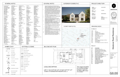
GENERAL NOTES GENERAL NOTES EXTERIOR PERSPECTIVE PROJECT DIRECTORY A.F.F. Above Finish Floor A.P. Access Panel ACOUS. Acoustical A.C.T. Acoustic Ceiling Tile A.C.P. Acoustic Ceiling Panel ADD'N Addition, Additional ADJ. Adjustable AGGR. Aggregate ALUM. Aluminum ALT. Alternate ANOD. Anodized APPR. Approved APPROX. Approximate ARCH. Architect, Architectural ASPH. Asphalt AUTO Automatic AUX. Auxiliary BKR. BD.Backer Board BSPL. Backsplash B.F. Barrier Free B. PL. Base Plate BSM'T Basement BM Beam BR'G Bearing B.M. Bench Mark BTW. Between BEV. Beveled BLK. Block BLK'G Blocking BD. Board B.O.S. Bottom of Slab BOT. Bottom B.U.R. Built-Up Roofing BLDG. Building CAB. Cabinet CPT. Carpet C.I.P. Cast-In-Place C.I. Cast Iron CDR. Cedar CLG. Ceiling C.H. Ceiling Height CEM. Cement or Cementitious C.P. Cement Plaster CTR. Center C/L Center Line C/C Center To Center CER. Ceramic C.T. Ceramic Tile C Channel CLO. Closet CLOS. Closure CLR. Clear C.M.U. Concrete Masonry Unit C.O. Clean Out COL. Column CW Cold Water COMP. Composite, Compacted CONC. Concrete CONN. Connect, Connection CONF. Conference CONTR. Contractor C.J. Control Joint CONSTR. Construction CONT. Continuous CORR. Corridor, Corrugated CTSK. Countersunk CNTR. Counter D.P. Dampproofing D.L. Dead Load DEMO. Demolition, Demolish DEPT. Department DET. Detail DIA. Diameter DIM. Dimension DIR. Directory, Direction D.W. Dishwasher DISP. Dispenser DISPO. Disposal DN. Down DR. Door D.O. Door Opening DBL. Double DS. Downspout DWR. Drawer DWG. Drawing D.S.P. Dry Standpipe D Dryer EA. Each E.F. Exhaust Fan E. East EL. Elevation ELEC.Electric, Electrical E.O.Electrical Outlet ELEV.Elevator ELIM.Eliminate EMER.Emergency ENAM.Enamel ENCL.Enclosure ENVIR.Environment EQ.Equal EQPT.Equipment EXC.Excavated EXP.Expansion EXP.B.Expansion Bolt E.J.Expansion Joint EXT.Exterior E.S.Exist Sign EXTG.Existing EXPO.Exposed FAB.Fabric F.A.Fire Alarm FAST.Fastener F.D.Floor Drain FDN.Foundation F.E.Fire Extinguisher F.F.Finished Floor F.H.C.Fire Hose Cabinet FIN.Finish FIXT.Fixture FLASH.Flashing FLR.Floor F.O. Finished Opeining F.O.C.Face of Concrete F.O.F.Face of Finish F.O.I.C.Furnished by Owner, Installed by Contractor F.O.M.Face of Masonry F.O.S.Face of Studs FPRF.Fireproof F.P.Floor Plan FT.Feet, Foot FTG.Footing FURN.Furnish, Furnished FURR.Furring FUT.Future G.A.Gauge GALV.Galvanized G.Gas G.C. General Contractor G.C.Gypsum Concrete GEN.General G.F.I.Ground Fault Interrupter GL.Glass GND.Ground G.R.Guard Rail GR.Grade GSM.Galvanized Sheet Metal GWB.Gypsum Wall Board GYP.Gypsum H.C.Handicapped H.R.Handrail HGR.Hanger HDWR.Hardware HDWD.Hardwood HD.Head HVAC.Heating, Ventilation & Air Conditioning HGT.Height H.P.High Point H.C.Hollow Core HCWD Hollow Core Wood Door H.M.Hollow Metal HORIZ.Horizontal H.B.Hose Bibb H.W.Hot Water H.W.H.Hot Water Heater HR.Hour HYD.Hydrant I.D. Inside Diameter (Dim.) INFO. Information IN. Inch or Inches INSUL. Insulation or Insulated INT. Interior JAN. Janitor J.S. Joint sealant JST. Joist JT. Joint K.O.P.Knock-out Panel KIT.Kitchen LAM.Laminate LAV.Lavatory L.H.Left Hand LKR.Locker L.P.Low Point L.S.Light Switch LT.Light LT. WT.Lightweight L.L.Liveload MACH.Machine MH.Manhole MFR.Manufacturer MARB. Marble MAS.Masonry M.O. Masonry Opening MAT'LMaterial MAX. Maximium MED.Medium MECH. Mechanical MEMB. Membrane MET./MTL.Metal or Metallic MEZZ.Mezzanine MICR. Microwave Oven MISC.Miscellaneous MIN. Minimum MIR. Mirror MTD.Mounted MUL.Mullion NOM. Nominal N. North N.I.C. Not In Contract N.T.S.Not To Scale NO. Number OFF.Office O.C.On Center O.H.Opposite Hand OPN'G.Opening OPP.Opposite O.D.Outside Diameter (Dim.) O.A.Overall O.H.Overhead PTD.Painted PR.Pair PNL.Panel P.H.Panic Hardware PTN.Partition PVM'T.Pavement PERF.Perforated PERIM.Perimeter PL.Plate PLAM.Plastic Laminate PLAS.Plaster PLYWD.Plywood PT.Point LBS.Pounds P.S.F.Pounds Per Square Foot P.S.L. Parallel Strand Lumber PWR.Power P.C.Pre-Cast P.T.Pressure Treated PROP.Property PVC.Polyvinyl Chloride Q.T.Quarry TIle RAD.Radius REF.Reference REFL.Reflected REFR.Refrigerator RGTR.Register REINF.Reinforced REQ'D.Required RESIL.Resilient RET.Retaining REV.Revised, Revision R.Riser R.D.Roof Drain R.D.O.Roof Drain Overflow RF'G.Roofing RM.Room R.O.Rough Opening RND.Round SAN.Sanitary SCHED.Schedule SCR.Scupper SLNT.Sealant SECT.Section S.South or Sink S.C.Solid Core S.D. Smoke Detector SHT'GSheathing SHT.Sheet SH.Shelf SHR.Shower SIM.Similar SNGL.Single SL.Slope SL.T.D.Slope to Drain S.Disp.Soap Dispenser SPK'RSpeaker SPEC.Specification SPSprinkler SQ.Square S.F.Square Feet (Foot) STAG'DStaggard SST.Stainless Steel STA.Station STN.Stain or Stained ST'D.Standard STL.Steel STOR.Storage STRUC.Structural SURF.Surface SUSP.Suspended SYM.Symmetrical TEL.Telephone T.V.Television TEMP.Temperature TEMP. GL.Tempered Glass THK.Thick T'HLD.Threshold T.O.C.Top of Concrete T.O.P.Top of Plate T.O.S.Top of Steel T.P.Top of Pavement T.O.W.Top of Wall T.P.H.Toilet Paper Holder T&G.Tounge & Groove T.B.Towel Bar T.C.Trash Compactor T.Tread TRTD.Treated TYP.Typical UNF.Unfinished U.O.N.Unless Otherwise Noted UR.Urinal VAR.Varies VERT.Vertical VEST.Vestibule V.I.F.Verify In Field V.P.Veneer Plaster V.C.T.Vinyl Composition Tile V.Volt WSCT.Wainscot W.C.Water Closet W.H.Water Heater WP. Waterproof(ing) W.R.Water Resistant WT.Weight W.W.M.Welded Wire Mesh W.West, Washer W/.With WDW.Window R.O.Rough Opening W/O.Without WD.Wood YD.Yard & And L Angle @ At # Pound or Number 1. 2. 3. 4. 5. 6. 7. 8. 9. 10. 11. 12. 13. 14. 15. 16. 17. The Contractor shall thoroughly review all Construction Documents including, but not limited to, drawings, notes, dimensions, schedules and specifications. The Contractor shall make a site visit and perform a detailed analysis and shall immediately bring any inconsistency, site layout problem, or any other request for clarification to the Architect for resolution prior to the delivery of any bid or initiation of work. Failure to do so shall cause the contractor to be ineligible for extras relating to such matters. These drawings are, in general, diagrammatic. Exact locations shall be determined by the Contractor from field measurements taken by Contractor's personnel. Actual arrangement of the work shall follow locations shown on the drawings within the constraints of existing equipment and construction, where such conditions exist. Drawing and notes to drawings are correlative and have equal authority and priority. Should there be discrepancies in themselves or between them, Contractor shall base bid pricing on the most expensive combination of quality and/or quantity of the work indicated. In the event of discrepancies, obtain clarification from Architect before continuing work. DO NOT SCALE THESE DRAWINGS. Immediately notify the Architect of any discrepancies or any other request for clarification. Verify all dimensions before ordering material and proceeding with the work. Minimum clearance dimensions indicated shall be maintained particularly at stairs, corridors and restrooms. Contractor to acquire all necessary permits prior to work. Contractor is responsible for the safety, actions, and conduct of his employees and his subcontractors' employees while in the project area, adjacent areas and in the building and its vicinity. Upon completion of work Contractor shall remove all debris from the site. Contractor shall submit reproducible shop drawings to Architect for Owner's, Architect's, and Engineer's Approval. All materials, finishes, manufactured items, and equipment shall be installed in full accordance with the supplier's or manufacturer's written recommendations or these documents, whichever is more restrictive. Notify the Architect of any variation in dimensions required for installation of equipment from those given in the Construction Documents before continuing the work. Every effort has been made on the part of the Architect to ensure local code compliance. It is the Contractor's responsibility to verify that the work conforms with all applicable codes and if discrepancies are noted to notify the Architect prior to work. Minor details not usually shown or specified but necessary for proper construction of any part of the work shall be included as if they were indicated on the drawings. Provide blocking as required for proper support of wall and ceiling mounted equipment or architectural elements. For all "match existing" notes Architect's intent is for Contractor to match existing profile and finish as closely as possible using available materials. If unable to match existing provide samples for alternate materials or methods for Architect's approval. Dissimilar metals to remain separated to avoid galvanic corrosion. All ceilings to be sheathed with 5/8" gypsum board unless otherwise noted. All interior paints, stains, and sealants to be low or no VOC rated. Contractor to notify architect and engineer(s) of any contradictory dimensions, specifications or other instructions that exist between the architectural, mechanical, electrical, plumbing, or other drawings that are included in the construction documents before continuing work VICINITY MAP (NTS) 1317 Westover Road SYMBOLS KEY MATERIALS LEGEND BUILDING KEY PLAN 1 View Name 1/8" = 1'-0" DRAWING TITLE WOOD, FINISH " 6 - ' 1 1 6 611' - 0" 6 1 0' - 6" " 0 - ' 0 1 6 " 6 9' - 0 6 " 0 9' - 0 6 " 6 - ' 8 0 6 0 COLUMN GRID 101 DOOR NUMBER WINDOW NUMBER Room name 101 ROOM NUMBER 1i PARTITION TYPE EXTERIOR ELEVATION MARKER 1 A101 DETAIL MARKER WALL SECTION MARKER DETAIL MARKER 1 A101 1 INTERIOR ELEVATION MARKER A101 1 A101 A101 1i 1 1 1 1 1 SPOT ELEVATION MARKER CONCRETE Name Elevation ELEVATION MARKER REVISION NUMBER WOOD, CONTINUOUS WOOD BLOCKING PLYWOOD, OSB, or MDF/MDO GYPSUM BOARD OR VENEER PLASTER ACOUSTIC CEILING PANEL BATT INSULATION RIGID INSULATION SEALANT, BACKING ROD STEEL or CAST IRON FIBER CEMENT BOARD CARPET ON PAD STONE CMU " 6 - ' 1 1 6 " 6 - ' 1 1 6 UP DN DW DN " 0 - 0' 1 6 UP " 6 - ' 9 0 6 6 1 1' - 6" 0 " - 6 1 1 ' " 6 - ' 0 1 6 610' - 0" " 6 - ' 9 0 6 " 0 - ' 9 0 6 " 6 - ' 8 0 6 LEGAL DESCRIPTION LOT 11 *& E 10 FT OF LOT 10 *& W 10 FT OF LOT 12 BLK 15 PEMBERTON HEIGHTS SEC 3 These drawings are property of the architect and may not be reproduced, distributed, published, or used in any way without written consent of the architect. Architect: Sanders Architecture 3706 Kerbey Lane Austin, TX 78731 (512) 482-9258 Owner: John and Liz Wright 1610 West Ave. Austin, TX 78701 Contractor: Miars Construction 2001 La Casa Austin, TX 78704 Structural Engineer: Structures, Inc. 6926 N. Lamar Blvd. Austin, TX 78752 (512) 499-0919 Landscape Architect: Civil Engineer: Geotechnical Engineer: Surveyor: SNS Engineering 12885 US Highway 183 North Suite 101-B Austin, TX 78750 (512) 335-3944 DRAWING INDEX Architectural Structural G0.00 G1.00 G1.01 G1.02 G1.03 G1.04 G2.01 A1.00 A1.01 A1.02 A1.03 A1.04 A3.01 A3.02 A3.03 S0.0 S0.1 S1.0 S1.1 S2.0 S2.1 S2.2 S2.3 S2.4 SL2.0 SL2.1 SL2.2 SL2.3 SL2.4 S3.0 S3.1 S3.2 S3.3 S4.0 S4.1 S5.0 S5.1 S5.2 S5.3 Cover Site Survey Proposed Site Plan Subchapter F Setback Compliance Subchapter F Setback Compliance Visitability Plan Door and Window Schedules Basement Floor Plan Ground Floor Plan Second Floor Plan Roof Plan Carport / Garage and Accessory Unit Plans Exterior Elevations Exterior Elevations Carport / Garage and Accessory Unit Elevations Structural Notes Structural Notes Basement Foundation Plan Garage and Carport Foundation Plan Ground Floor Foundation / Framing Plan Second Floor and Low Roof Framing Plan Roof Framing Plan Garage and Carport Framing Plan Efficiency Roof Framing Plan Ground Floor Lateral Bracing Plan Second Floor and Low Roof Lateral Bracing Plan Roof Lateral Bracing Plan Garage and Carport Lateral Bracing Plan Efficiency Lateral Bracing Plan Typical Foundation Details Foundation Details Foundation Details Foundation Details Typical Steel Framing Details Typical Steel Framing Details Typical Wood Framing Details Typical Wood Framing Details Typical Shear Wall Details Wood Details 07.28.2020 Copyright: These drawings are property of the architect and may not be reproduced, distributed, published, or used in any way without written consent of the architect. i e c n e d s e R d a o R r e v o t s e W d a o R r e v o t s e W 7 1 3 1 3 0 7 8 7 X T , n i t s u A CP-1 Construction Documents 07.28.2020 Drawn by: WP, EK Checked by: CS Revisions: Cover G0.00 07.28.2020 Copyright: These drawings are property of the architect and may not be reproduced, distributed, published, or used in any way without written consent of the architect. i e c n e d s e R d a o R r e v o t s e W d a o R r e v o t s e W 7 1 3 1 3 0 7 8 7 X T , n i t s u A CP-1 Construction Documents 07.28.2020 Drawn by: WP, EK Checked by: CS Revisions: Site Survey G1.00 Number Location Width Height Thickness Type Material Finish Type Finish Comments Mark Location Manufacturer Operation Width Height Rough Width Ext Finish Int Finish Comments Garage 9' - 8" 8' - 0" 1 3/4" Wood-clad 11' - 3" 12' - 9 3/4" 11' - 3 3/4" 11' - 3" Steel and glass window wall with swing door Trimless door W-118 Screen Porch Rehme Steel Windows & Fixed 9' - 0" 17' - 1" 9' - 0 3/4" 9' - 0" Steel and glass window wall with sliding door Kitchen 3' - 0" 8' - 0" 2" Aluminum/glass Aluminum/Wood Powder-coated 1-Wide Outswing VistaLuxe Entrace Door Basis of design: Kolbe VistaLuxe Exterior Door Media Room 2' - 8" 7' - 0" 1 3/4" Media Room 2' - 8" 7' - 0" 1 3/4" Dining Room 2' - 8" 7' - 0" 1 3/4" Pantry 3' - 0" 7' - 0" 1 3/4" Entry 3' - 0 3/4" 8' - 3 3/4" 2" Steel/glass Laundry 2' - 8" 7' - 0" 1 3/4" Wood Living Room 6' - 7 3/4" 9' - 0" 1 3/4" Steel/glass Master Bedroom 3' - 0" 7' - 0" 1 3/4" Master Bedroom 2' - 4" 7' - 0" 1 3/4" Master Bath 2' - 6" 7' - 0" 1 3/4" Master Closet 3' - 0" 7' - 0" 1 3/4" Powder 2' - 8" 7' - 0" 1 3/4" Closet Stairs 2' - 4" 7' - 0" 1 3/4" 3' - 0" 7' - 0" 1 3/4" Garage 3' - 0" 7' - 0" 2" Bedroom 2 2' - 8" 7' - 0" 1 3/4" 202a Bathroom 2 2' - 4" 7' - 0" 1 3/4" 202b Bathroom 2 2' - 4" 7' - 0" 1 3/4" Bedroom 4 2' - 8" 7' - 0" 1 3/4" Bathroom 4 2' - 4" 7' - 0" 1 3/4" Bedroom 3 2' - 4" 7' - 0" 1 3/4" Hall landing 2' - 8" 7' - 0" 1 3/4" Door and Frame Schedule Door Frame Material Painted, color TBD Painted, color TBD Painted, color TBD Painted, color TBD Painted, color TBD Powder-coated, color TBD Painted, color TBD Painted, color TBD Painted, color TBD Painted, color TBD Painted, color TBD Painted, color TBD Painted, color TBD Painted, color TBD Painted, color TBD Powder-coated, color TBD Powder-coated, color TBD Painted, color TBD Painted, color TBD Painted, color TBD Painted, color TBD Painted, color TBD Painted, color TBD Painted, color TBD Powder-coated, color TBD Powder-coated, color TBD Painted, color TBD Powder-coated, color TBD F4 F4 F1 F7 F7 F3 F4 F2 F4 D7 F4 F7 F7 F4 F4 F9 F6 F5 F4 D7 D7 F4 D7 D7 F4 F8 F3 F7 F3 Wood Wood Steel Wood Wood Wood Steel Wood Wood Wood Wood Wood Wood Wood Wood Metal Wood Wood Wood Wood Wood Wood Wood Wood Painted, color TBD Painted, color TBD Painted, color TBD Painted, color TBD Painted, color TBD color TBD Painted, color TBD Painted, color TBD Painted, color TBD Painted, color TBD Painted, color TBD Painted, color TBD Painted, color TBD Painted, color TBD Painted, color TBD Powder-coated color TBD Powder-coated color TBD Painted, color TBD Painted, color TBD Painted, color TBD Painted, color TBD Painted, color TBD Painted, color TBD Painted, color TBD color TBD color TBD Painted, color TBD color TBD Wood Wood Wood Wood Wood Wood Wood Wood Wood Wood Wood Wood Wood Wood Wood Wood Wood Wood Wood D4 D4 D1 D7 D7 D8 D4 D2 D4 D7 D4 D7 D7 D4 D4 D6 D9 D4 D7 D7 D4 D7 D7 D4 D8 D3 D7 D3 001 002 100 101 102 103 104 105 106 107 108 109 110 111 112 113 114 201 204 205 206 207 208 209 210 211 Fixed 4' - 0" 4' - 6" 4' - 0 3/4" 4' - 6 1/2" 8' - 0" Butt glazed corner window Window Schedule Rough Height Head Height W-001 Media Room Casement 4' - 0" 4' - 0" 4' - 0 3/4" 4' - 0 3/4" 7' - 0" W-101 Master Bedroom W-102 Master Bedroom W-103 Master Bedroom W-104 Master Bath W-105 Master Bath W-106 Master Bath Kolbe & Kolbe Millwork Co., Inc. Kolbe & Kolbe Millwork Co., Inc. Kolbe & Kolbe Millwork Co., Inc. Kolbe & Kolbe Millwork Co., Inc. Kolbe & Kolbe Millwork Co., Inc. Kolbe & Kolbe Millwork Co., Inc. Kolbe & Kolbe Millwork Co., Inc. Fixed Fixed Fixed Fixed Fixed 10' - 0" 7' - 0" 10' - 0 1/2" 7' - 0 1/2" 8' - 9" 2' - 0" 3' - 0" 2' - 0 3/4" 3' - 0 3/4" 8' - 0" 2' - 0" 3' - 0" 2' - 0 3/4" 3' - 0 3/4" 8' - 0" Casement 2' - 0" 3' - 0" 2' - 0 1/2" 3' - 0 1/2" 7' - 0" 2' - 0" 3' - 0" 2' - 0 3/4" 3' - 0 3/4" 7' - 0" 2' - 0" 3' - 0" 2' - 0 3/4" 3' - 0 3/4" 8' - 0" W-107 Master Closet Kolbe & Kolbe Millwork Co., Fixed 2' - 0" 3' - 0" 2' - 0 3/4" 3' - 0 3/4" 7' - 0" W-108 Master Closet Kolbe & Kolbe Millwork Co., Fixed 7' - 0" 8' - 0" 7' - 0 1/2" 8' - 0 1/2" 9' - 0" W-109 Dining Room Kolbe & Kolbe Millwork Co., Fixed 7' - 0" 8' - 0" 7' - 0 1/2" 8' - 0 1/2" 9' - 0" W-110 Dining Room Kolbe & Kolbe Millwork Co., Casement 3' - 6" 8' - 0" 3' - 6 1/2" 8' - 0 1/2" 9' - 0" Fixed Fixed Fixed Fixed Fixed Fixed Fixed Fixed Fixed Inc. Inc. Inc. Inc. Kolbe & Kolbe Millwork Co., Inc. Kolbe & Kolbe Millwork Co., Inc. Kolbe & Kolbe Millwork Co., Inc. Kolbe & Kolbe Millwork Co., Inc. Doors Rehme Steel Windows & Doors Kolbe & Kolbe Millwork Co., Inc. Kolbe & Kolbe Millwork Co., Inc. Kolbe & Kolbe Millwork Co., Inc. Kolbe & Kolbe Millwork Co., Inc. Kolbe & Kolbe Millwork Co., Inc. Kolbe & Kolbe Millwork Co., Inc. Kolbe & Kolbe Millwork Co., Inc. Kolbe & Kolbe Millwork Co., Inc. Kolbe & Kolbe Millwork Co., Inc. Kolbe & Kolbe Millwork Co., Inc. Kolbe & Kolbe Millwork Co., Inc. Kolbe & Kolbe Millwork Co., Inc. Kolbe & Kolbe Millwork Co., Inc. Kolbe & Kolbe Millwork Co., Inc. Kolbe & Kolbe Millwork Co., Inc. Kolbe & Kolbe Millwork Co., Inc. Inc. W-114 Laundry W-115 Kitchen W-116 Kitchen W-117 Pantry W-119 Entry W-201 Bedroom 3 W-202 Bedroom 3 W-203 Bedroom 3 W-204 Bedroom 3 W-205 Bedroom 3 W-206 Bathroom 3 W-207 Bathroom 4 W-208 Bedroom 4 W-209 Bedroom 4 W-210 Bedroom 4 W-211 Bedroom 4 W-213 Bedroom 2 W-213 Bedroom 2 W-215 WC W-216 Bathroom 2 W-217 Hall landing Casement 7' - 0" 4' - 6" 7' - 0 1/2" 4' - 6 1/2" 8' - 0" 4' - 0" 4' - 6" 4' - 0 1/2" 4' - 6 1/2" 8' - 0" 4' - 0" 4' - 6" 4' - 0 1/2" 4' - 6 1/2" 8' - 0" 17' - 0 1/4" 12' - 9" 2' - 0" 3' - 0" 2' - 0 3/4" 3' - 0 3/4" 7' - 0 3/4" Clad Wood, color 2' - 6" 2' - 6" 2' - 0" 2' - 6 1/2" 7' - 0 3/4" 7' - 0 3/4" 3' - 0" 2' - 0 3/4" 2' - 6 1/2" 7' - 1 1/4" 7' - 0 3/4" Clad Wood, color 7' - 1 1/4" 7' - 0 3/4" Clad Wood, color 3' - 0 3/4" 7' - 0 3/4" Clad Wood, color 2' - 0" 3' - 0" 2' - 0 3/4" 3' - 0 3/4" 7' - 0 3/4" Clad Wood, color Casement 2' - 0" 3' - 0" 2' - 0 1/2" 3' - 0 1/2" 7' - 0 3/4" Clad Wood, color Casement 2' - 0" 3' - 0" 2' - 0 1/2" 3' - 0 1/2" 7' - 0 3/4" Clad Wood, color 2' - 0" 3' - 0" 2' - 0 3/4" 3' - 0 3/4" 7' - 0 3/4" Clad Wood, color 2' - 0" 3' - 0" 2' - 0 3/4" 3' - 0 3/4" 7' - 0 3/4" Clad Wood, color 7' - 0" 7' - 0" 7' - 0 1/2" 7' - 0 1/2" 9' - 11 1/4" Clad Wood, color Fixed 7' - 0" 6' - 0" 7' - 0 1/2" 6' - 0 1/2" 6' - 11 1/4" Clad Wood, color Casement 2' - 0" 3' - 0" 2' - 0 1/2" 3' - 0 1/2" 5' - 4" Casement 2' - 0" 3' - 0" 2' - 0 1/2" 3' - 0 1/2" 7' - 0" Casement 2' - 0" 3' - 0" 2' - 0 1/2" 3' - 0 1/2" 7' - 0" Clad Wood, color TBD Clad Wood, color TBD Clad Wood, color TBD Clad Wood, color TBD Clad Wood, color TBD Clad Wood, color TBD Clad Wood, color TBD Clad Wood, color TBD Clad Wood, color TBD Clad Wood, color TBD Clad Wood, color TBD Clad Wood, color TBD Clad Wood, color TBD Clad Wood, color TBD Clad Wood, color TBD Painted Steel, color TBD Painted Steel, color TBD TBD TBD TBD TBD TBD TBD TBD TBD TBD TBD Clad Wood, color TBD TBD Clad Wood, color TBD Clad Wood, color TBD Clad Wood, color TBD Painted Steel, color TBD Clad Wood, color TBD Clad Wood, color TBD Clad Wood, color TBD TBD TBD Painted, color TBD Painted, color TBD Painted, color TBD Painted, color TBD Painted, color TBD Painted, color TBD Painted, color TBD Painted, color TBD Painted, color TBD Painted, color TBD Painted, color TBD Painted, color TBD Painted, color TBD Painted, color TBD Painted, color TBD Painted Steel, color TBD Painted Steel, color TBD Painted, color TBD Painted, color TBD Painted, color TBD Painted, color TBD Painted, color TBD Painted, color TBD Painted, color TBD Painted, color TBD Painted, color TBD Painted, color TBD Painted, color TBD Painted, color TBD Painted, color TBD Painted, color TBD Painted, color TBD Painted, color TBD Painted, color TBD Painted, color TBD Painted, color TBD TBD TBD Dormer 4' - 0" 6' - 3" 6' - 3 1/2" 4' - 0 1/2" 10' - 6" Custom dormer window, butt glazed corners W-218 Accessory Unit Kolbe & Kolbe Millwork Co., Fixed 7' - 0" 4' - 0" 7' - 0 1/2" 4' - 0 1/2" 7' - 0" W-219 Accessory Unit Kolbe & Kolbe Millwork Co., Fixed 10' - 0" 7' - 0" 10' - 0 1/2" 7' - 0 1/2" 7' - 0" W-220 Bathroom 2' - 0" 3' - 0" 2' - 0 3/4" 3' - 0 3/4" 7' - 0" Inc. Kolbe & Kolbe Millwork Co., Inc. TBD TBD Fixed Fixed Fixed W-301 W-302 2' - 0" 2' - 0" 4' - 0" 2' - 0 1/2" 4' - 0" 2' - 0 1/2" 4' - 0 1/2" 4' - 0 1/2" Skylight at Bedroom 2 Skylight at Accessory Unit Bedroom 3 6' - 0" 7' - 0 3/4" Accessory Unit 3' - 0" 7' - 0" 2" 2" Aluminum/glass Aluminum/glass Bathroom 2' - 8" 7' - 0" 1 3/4" Wood Aluminum/Wood Powder-coated 1-Wide Outswing VistaLuxe Entrace Door Basis of design: Kolbe VistaLuxe Exterior Door Basis of design: Kolbe VistaLuxe Exterior Door Aluminum/Wood Powder-coated 1-Wide Outswing VistaLuxe Entrace Door Basis of design: Kolbe VistaLuxe Exterior Door Terrace 3' - 0" 7' - 0" 2" Aluminum/glass Aluminum/Wood Powder-coated 1-Wide Outswing VistaLuxe Entrace Door Basis of design: Kolbe VistaLuxe Exterior Door Casement 2' - 0" 3' - 0" 2' - 0 1/2" 3' - 0 1/2" 6' - 0" 07.28.2020 Copyright: These drawings are property of the architect and may not be reproduced, distributed, published, or used in any way without written consent of the architect. i e c n e d s e R d a o R r e v o t s e W d a o R r e v o t s e W 7 1 3 1 3 0 7 8 7 X T , n i t s u A CP-1 Construction Documents 07.28.2020 Drawn by: WP, EK Checked by: CS Revisions: Door and Window Schedules G2.01 1 2 3 4 5 16' - 9 1/2" 14' - 8 1/2" 3' - 9" 10' - 4 1/2" Gutter Gutter DS DS Steel plate awning DS Slope 12:12 Slope 12:12 e p o S l : 2 1 5 2 . 0 Slope 12:12 Slope 12:12 Gutter DS " 2 1 / 5 - ' 2 t h g i l y k s W-301 e p o S l : 2 1 0 1 A3.01 2 e p o S l 2 1 : 3 e p o S l : 2 1 0 1 Exhaust stack chimney 1 A3.02 Steel plate awning Slate roof, typ. RD slope 2% typ. @ membrane roof e p o S l 2 1 : 2 DS A B C D E F G " 2 1 / 3 - ' 0 1 " 2 1 / 9 - ' 3 " 2 - ' 7 " 4 1 / 6 - ' 8 1 " 4 - ' 0 1 " 6 - ' 1 Exhaust stack chimney Chimney DS Wood deck over TPO roof N 1 Roof Plan 1/4" = 1'-0" GENERAL PLAN NOTES: 1. Elevation 100'-0" as noted equals 613'-6" natural elevation above sea level. 2. Refer to G2.01 for wall types. 3. All dimensions to face of framing unless otherwise specified. 4. Maintain R13 minimum insulation for exterior walls. All insulation to be either labeled or the installed R-values provided. All insulation to be installed per manufacturer's instructions. All air barriers and thermal barriers to be installed per manufacturer's instructions. 5. Maintain R38 minimum insulation for attics and roofs, typ. All insulation to be either labeled or the installed R-values provided. All insulation to be installed per manufacturer's instructions. All air barriers and thermal barriers to be installed per manufacturer's instructions. Attic spaces to be unvented with air-impermeable insulation at underside of roof sheathing. 6. Provide carbon monoxide detectors in vicinity of sleeping rooms in accordance with IRC R315. 7. Provide smoke detector system (hardwired, interconnected, battery back-up) at each sleeping room and vicinity in accordance with IRC R314. 8. Residential fire sprinkler system to be designed and installed in accordance with the latest version oft he Nation Fire Protection Association (NFPA) 13D. SUBMIT SPRINKLER PLANS TO ARCHITECT, ALLOWING REASONABLE TIME FOR REVIEW BEFORE INSTALLATION OR ANY REQUIRED AGENCY APPROVAL. 07.28.2020 Copyright: These drawings are property of the architect and may not be reproduced, distributed, published, or used in any way without written consent of the architect. i e c n e d s e R d a o R r e v o t s e W d a o R r e v o t s e W 7 1 3 1 3 0 7 8 7 X T , n i t s u A CP-1 Construction Documents 07.28.2020 Drawn by: WP, EK Checked by: CS Revisions: Roof Plan A1.03 Legend: S Wall Mounted Smoke Alarm/ Carbon Monoxide Detector GENERAL PLAN NOTES: 1. Elevation 100'-0" as noted equals 613'-6" natural elevation above sea level. 2. Refer to G2.01 for wall types. 3. All dimensions to face of framing unless otherwise specified. 4. Maintain R13 minimum insulation for exterior walls. All insulation to be either labeled or the installed R-values provided. All insulation to be installed per manufacturer's instructions. All air barriers and thermal barriers to be installed per manufacturer's instructions. 5. Maintain R38 minimum insulation for attics and roofs, typ. All insulation to be either labeled or the installed R-values provided. All insulation to be installed per manufacturer's instructions. All air barriers and thermal barriers to be installed per manufacturer's instructions. Attic spaces to be unvented with air-impermeable insulation at underside of roof sheathing. 6. Provide carbon monoxide detectors in vicinity of sleeping rooms in accordance with IRC R315. 7. Provide smoke detector system (hardwired, interconnected, battery back-up) at each sleeping room and vicinity in accordance with IRC R314. 8. Residential fire sprinkler system to be designed and installed in accordance with the latest version oft he Nation Fire Protection Association (NFPA) 13D. SUBMIT SPRINKLER PLANS TO ARCHITECT, ALLOWING REASONABLE TIME FOR REVIEW BEFORE INSTALLATION OR ANY REQUIRED AGENCY APPROVAL. Zinc half round gutter, typ Slope 12:12 Slope 12:12 t h g i l y k s W-302 " 4 - ' 5 DS A3.03 2 DS RD A3.03 2 2' - 0" Carport F.F. 96' - 8" Garage F.F. 96' - 8" 2' - 5 1/4" door 113 Carport 113 Q E Q E DS H " 4 1 / 9 - ' 4 2 A3.03 1 " 2 1 / 7 - ' 2 1 " 4 3 / 1 - ' 2 1 N I " 4 3 / 4 - ' 3 UP H I " 4 1 / 9 - ' 4 2 " 4 3 / 4 - ' 3 A3.03 2 DS EQ EQ W-219 Accessory Unit 209 W-218 window Accessory Unit F.F. 107' - 2 3/4" S 210 sink 1' - 4" Terrace 211 T.O. Deck 107' - 2 1/4" 211 " 4 1 / 3 - ' 9 " 1 1 - ' 1 " 4 / 1 1 1 - ' 6 209 DS W-220 DN R L C " 4 / 1 0 - ' 3 4' - 0" 4' - 6 1/2" EQ EQ 7' - 5" window/toilet 13' - 6 1/2" door 3 A3.03 6 N H " 4 / 1 9 - ' 4 2 I 3 Garage and Carport Floor Plan 1/4" = 1'-0" 2 Guest House Floor Plan 1/4" = 1'-0" 7' - 5" 13' - 6 1/2" 3 A3.03 6 7 8 7 8 6 7 8 7' - 5" 13' - 6 1/2" 3 A3.03 N 1 Guest House Roof Plan 1/4" = 1'-0" 4 A3.03 A3.03 1 4 A3.03 A3.03 1 4 A3.03 Garage 114 114 EQ EQ Bathroom 210 " 0 - ' 2 r o o d slope 2% typ. @ membrane roof RD 07.28.2020 Copyright: These drawings are property of the architect and may not be reproduced, distributed, published, or used in any way without written consent of the architect. i e c n e d s e R d a o R r e v o t s e W d a o R r e v o t s e W 7 1 3 1 3 0 7 8 7 X T , n i t s u A CP-1 Construction Documents 07.28.2020 Drawn by: WP, EK Checked by: CS Revisions: Carport / Garage and Accessory Unit Plans A1.04 5 4 3 2 1 12 12 W-213 W-109 Steel guardrail, beyond 100 W-119 12 12 +1.5" -2" 0" W-210 W-108 A B C D E F G T.O. Ridge Main House 128' - 10" Slate roof T.O. Plate 2nd Floor 119' - 8 1/2" Zinc gutters and downspouts, typ. Steel windows and doors Brick surround at bay window F.F. Main House 2nd Floor 110' - 6 3/4" F.F. Main House Ground Floor 100' - 0" 1 North Elevation 1/4" = 1'-0" T.O. Ridge Main House 128' - 10" T.O. Plate 2nd Floor 119' - 8 1/2" F.F. Main House 2nd Floor 110' - 6 3/4" F.F. Main House Ground Floor 100' - 0" 2 West Elevation 1/4" = 1'-0" Zinc-clad chimney, beyond Brick Brick soldier course corbel (+1.5") Brick header course corbel (+1.5") Zinc chimney cap, beyond Brick chimney, beyond Aluminum-clad wood windows, typ. Brick corbel at chimney, beyond Brick soldier plinth course (+1.5") Zinc-clad chimney, beyond Zinc chimney cap Slate roof Brick Zinc gutters and downspouts, typ. Brick chimney Steel guardrail Brick header reveal (+1.5") Aluminum-clad wood windows, typ. Brick sill, typ. (+1.5") 07.28.2020 Copyright: These drawings are property of the architect and may not be reproduced, distributed, published, or used in any way without written consent of the architect. i e c n e d s e R d a o R r e v o t s e W d a o R r e v o t s e W 7 1 3 1 3 0 7 8 7 X T , n i t s u A CP-1 Construction Documents 07.28.2020 Drawn by: WP, EK Checked by: CS Revisions: Exterior Elevations A3.01 W-209 W-208 W-207 W-206 W-205 W-204 W-107 W-105 W-104 W-103 W-102 W-106 Wood siding Brick corbel at chimney Brick soldier plinth course (+1.5") Steel guardrail @ stair and ramp 1 2 3 4 5 W-203 W-202 W-217 208 W-101 W-118 105 W-114 G F E D C B A W-301 W-217 W-201 W-216 W-215 W-114 W-116 W-115 W-117 103 W-110 Brick soldier plinth course (+1.5") Zinc-clad chimney, beyond Steel and glass dormer window Zinc chimney cap Slate roof Steel windows and doors Brick, typ. Zinc gutters and downspouts, typ. Aluminum-clad wood windows, typ. Brick sill, typ. (+1.5") Steel guardrail Zinc-clad chimney, beyond Skylight Slate roof Wood siding Brick, typ. Brick soldier course corbel (+1.5") Zinc gutters and downspouts, typ. Brick header course corbel (+1.5") Aluminum-clad wood windows, typ. T.O. Ridge Main House 128' - 10" Zinc chimney cap, beyond Brick soldier course corbel (+1.5") Brick header course corbel (+1.5") T.O. Plate 2nd Floor 119' - 8 1/2" Brick chimney, beyond F.F. Main House 2nd Floor 110' - 6 3/4" Steel guardrail Brick corbel at chimney, beyond Brick surround at bay window Brick soldier plinth course (+1.5") F.F. Main House Ground Floor 100' - 0" 2 South Elevation 1/4" = 1'-0" T.O. Ridge Main House 128' - 10" Zinc chimney cap T.O. Plate 2nd Floor 119' - 8 1/2" Steel and glasss dormer window Wood-clad chimney Steel guardrail F.F. Main House 2nd Floor 110' - 6 3/4" F.F. Main House Ground Floor 100' - 0" 1 East Elevation 1/4" = 1'-0" 07.28.2020 Copyright: These drawings are property of the architect and may not be reproduced, distributed, published, or used in any way without written consent of the architect. i e c n e d s e R d a o R r e v o t s e W d a o R r e v o t s e W 7 1 3 1 3 0 7 8 7 X T , n i t s u A CP-1 Construction Documents 07.28.2020 Drawn by: WP, EK Checked by: CS Revisions: Exterior Elevations A3.02 8 7 6 H I T.O. Ridge Efficiency 122' - 8 1/2" T.O. Ridge Efficiency 122' - 8 1/2" 12 12 W-218 Wood siding Aluminum-clad wood windows, typ. Zinc gutters and downspouts, typ. F.F. Efficiency 107' - 2 3/4" Zinc-clad panel F.F. Efficiency 107' - 2 3/4" Slate roof Aluminum-clad wood windows, typ. Zinc gutters and downspouts, typ. Wood siding, typ. Steel guardrail W-219 211 F.F. Garage/Carport 96' - 8" 2 Garage/Carport and Efficiency Room South Elevation 1/4" = 1'-0" F.F. Garage/Carport 96' - 8" 1 Garage/Carport and Efficiency Room West Elevation 1/4" = 1'-0" 6 7 8 I H T.O. Ridge Efficiency 122' - 8 1/2" 12 12 Wood siding Aluminum-clad wood windows, typ. Zinc gutters and downspouts, typ. W-220 209 Steel guardrail F.F. Efficiency 107' - 2 3/4" F.F. Garage/Carport 96' - 8" T.O. Ridge Efficiency 122' - 8 1/2" F.F. Efficiency 107' - 2 3/4" F.F. Garage/Carport 96' - 8" W-302 114 3 Garage/Carport and Efficiency Room North Elevation 1/4" = 1'-0" 4 Garage/Carport and Efficiency Room East Elevation 1/4" = 1'-0" Slate roof Skylight Wood siding Steel guardrail Zinc gutters and downspouts, typ. Garage door, clad to match wood siding 07.28.2020 Copyright: These drawings are property of the architect and may not be reproduced, distributed, published, or used in any way without written consent of the architect. i e c n e d s e R d a o R r e v o t s e W d a o R r e v o t s e W 7 1 3 1 3 0 7 8 7 X T , n i t s u A CP-1 Construction Documents 07.28.2020 Drawn by: WP, EK Checked by: CS Revisions: Carport / Garage and Accessory Unit Elevations A3.03