B.1 - Littlefield Building canopy - drawing — original pdf
Backup
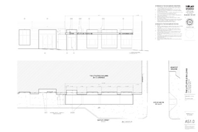
6 9 7 6 2 3 6 7 6 6 49'-5" 6'-4 7/8" " 0 1 - ' 2 " 0 - ' 1 " 0 1 - ' 3 " 4 - ' 1 1 8 5 4 2 AWNING ELEVATION SCALE: 1/4" = 1'-0" THE LITTLEFIELD BUILDING 601 S. CONGRESS 55'-9 7/8" 49'-5" ' 7 2 . 0 9 ' W " 0 0 0 0 ° 9 1 S 6'-4 7/8" 1'-0 1/4" 7'-6 3/4" 7'-1 5/8" 8'-0 3/4" 2'-8 1/4" 11'-4 3/8" 2'-8 1/4" 8'-10 7/8" N71°O5'42"W 160.00' " 8 / 7 3 - ' " 1 8 / 7 6 - ' 8 " 3 - ' 7 " 3 " 0 - ' 7 8 1 EXISTING CONCRETE PARALLEL 2 4 3 PARKING SPACES 2/AS1.0 EAST 6TH STREET 80' R.O.W. N 1 AWNING PLAN SCALE: 1/4" = 1'-0" C. B. Architectural Site Plan & Awning Elevation General Notes: The dimensions on this sheet are based off of the face of finish material or A. masonry. All dimensions are to face of finish material, edge of awning, or centerline of support, unless otherwise noted. Contractor (GC) to field verify all dimensions prior to construction and/or installation of any equipment, accessories, etc. If a discrepancy is identified, notify NolanStudio immediately. Elevations are shown for reference only. Refer to Building Plans, Sections, Wall Sections and Window Elevations for additional information. All glass to be tempered in areas required by applicable code. Refer to appropriate sheet and/or schedule for additional information/detail regarding items shown herein. Keynotes located on this sheet are for this sheet only. Do not scale the drawings. If a specific dimension is not given, contact NolanStudio for clarification. Refer to Sheet A0.01-General Conditions for additional information associated with, but not limited to: submittals, shop drawings, samples, cutting and patching, coordination and staging, protection of work. Install all products per manufacturer's recommendations. D. E. F. G. H. I. 3. 4. 5. Architectural Site Plan & Awning Elevation Key Notes: 1. 2. Lot line. Building mounted awning to match design of existing above entrance to building lobby. Coordinate with Building Owner for paint color & finish during construction. Location, spacing, & size of overhead hanger and turn-buckle shown for reference only. Refer to Structural Drawings for specifications and layout. Existing entrance to tenant space to remain. Slope in existing sidewalk not shown here, vertical dimensions taken from interior finish floor of restaurant tenancy, coordinate with Owner during installation for height above sidewalk. Existing window to remain, cover and protect throughout construction process as necessary. Sign mounted to face of awning structure by others, shown here for reference only, coordinate with Building Owner and Restaurant Tenant for power and lighting specifications. Existing entrance to building lobby to remain. Estimated location of existing awning shown for clarity only; verify in field as needed. 8. 9. 6. 7. 708 Rio Grande Austin Texas 78701 512.330.4243 NOLAN-ARCHITECT.COM seal JANUARY 29, 2020 consultant ADJACENT BUILDING CITY OF AUSTIN 20' ALLEY I G N D L I U B D L E I F E L T T I L E H T e u n e v A s s e r g n o C 1 0 6 1 0 7 8 7 s a x e T n i t s u A CONSTRUCTION SET JANUARY 29, 2020 j t c e o r p set date revision title sheet AWNING PLAN & ELEVATION AS1.0 copyright This drawing and all copyright therein are the sole and exclusive property of NolanStudio. Reproduction or use of this drawing in whole or part by any means in any way whatsoever without the prior written consent of NolanStudio is strictly prohibited.