B.12 - Uptown Sports Bar - PLANS — original pdf
Backup
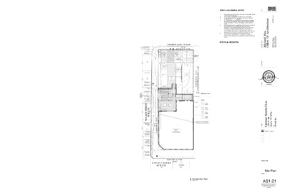
SITE PLAN GENERAL NOTES 1. 2. 3. 4. 5. 6. clarification. All spot elevations to be verified in field prior to construction. Notify MHOA of any discrepancies. Benchmark to be verified with architect prior to construction. Do not scale the drawings. If a specific dimension is not given, contact MHOA for GC is responsible for protecting and repairing additional damage arising during both demolition phase and new construction phase on existing partitions, finishes, and building elements that are to remain. Tree protection fencing is required for all existing trees 19 inches in diameter (60 inches in circumference) within the limits of construction. Fencing should protect the entire critical root zone (CRZ) area. Fencing is required to be chain-link mesh at a minimum height of five feet. A 6-inch layer of mulch within the entire available root zone area is required for trees which have any disturbance indicated within any portion of the critical root zone. Refer to General Requirements for additional information associated with, but not limited to: submittals, shop drawings, samples, cutting and patching, coordination and staging, protection of work. SITE PLAN KEYNOTES 21.01 Fire riser, refer to MEP. e r u t c e t i h c r A f O e c i f f O u s H l e a h c i M m o c . e c i f f O u s H 3 0 3 4 6 0 7 . ) 2 1 5 ( e c i f f O 6 5 7 8 7 s a x e T , n i t s u A d a o R t e n r u B 0 1 9 4 ì n Y m a e T n g s e D i t n a t l u s n o C ETSI ER I C M D A R C H H A E L H.H I T S U G E R E C T S A S T A 2 1 9 4 4 T E FO XE T l a e S 01/09/2020 l b u C s t r o p S n w o p tU 2 0 7 8 7 X T E 0 0 2 1 i t s u A h 6 t n , . e S t t e S t i m r e P -01/09/2020 -Permit Set t c e o r j P Issue: - - - - - - - - - - Drawing Title Site Plan Sheet AS1.01 This drawing and all copyright therein are the sole and exclusive property of Michael Hsu Office of Architecture. Reproduction or use of this drawing in whole or in part by any means in any way whatsoever without the prior written consent of Michael Hsu Office of Architecture is strictly prohibited. Copyright © 2019 Michael Hsu Office of Architecture CONCRETE ALLEY - 20' R.O.W. (47.5') S 60°00'54" E, 47.60' 1,442 SF Parking Area 4" Lacey Oak K C A B T E S Y T I L I B I T A P M O C ' 5 1 38 SF Retaining Wall Landscape/Gravel 896 SF Area 39 SF Retaining Wall 4" Lacey Oak Landscape/Gravel 415 SF Area 535 SF New Pedestrian Path DN 19 SF - 3'-0"h Retaining Wall DN 14'-0" " 0 - ' 1 1 DN DN 9'-0" " 6 - ' 9 DN 14'-0" 765 SF Accessible Path 15" Wooly Bumelia Total Mitigation Req'd = 7.5" ' 2 0 . 5 3 1 , W ' " 0 0 0 0 ° 0 3 S ) ' 5 3 1 , I I S S A B G N R A E B D E M U S S A ( New Grease Interceptor 25" Chinaberry 1/4 CRZ 1/2 CRZ 21.01 ) ' 5 3 1 ( ' 3 3 . 5 3 1 , ' E " 0 0 0 0 ° 0 3 N 2,749 SF Existing Cocktail Lounge Mitigation Provided in suitable natural area 4in 4in Legend New Impervious Flatwork New Acc. Path Impervious New Parking Impervious Repaired Parking Impervious 4.00 spaces (2.00) spaces t e e r t s - n o 5 g n i k r a p d e r e t e m " 0 - ' 2 2 s e c a p s Restriped parking on repaired existing impervious Trash / Recycle / Compost bin area Accessible Path Existing concrete sidewalk to remain " 0 - ' 2 2 " 0 - ' 2 2 " 0 - ' 2 2 " 0 - ' 2 2 " 1 - ' 0 3 6 5 4 New wood fence New underground electrical service Existing concrete sidewalk to remain New Accessible Ramp New wastewater connection, re: Civil Existing gas service & meter location, re: Civil New fire sprinkler water connection, re: Civil Existing water connection, re: Civil T E E R T S R E L L A W 3 . . W O R . ' 0 6 Existing wastewater connection per permit #25787, re: Civil 2 Repair parapet cap flashing Repair damaged column, paint to match existing Repair damaged wood slats individually in awning, paint to match existing Repair damaged lighting Repair damaged column, paint to match existing Repair damaged roof & framing N 60°23'52" W, 47.60' (47.5') 1 EAST 6TH STREET 60' R.O.W. 30'-0" 1 on-street metered parking space 22'-0" Proposed Site Plan 1 Overall Site Plan 3/32" = 1'-0" Fire riser, refer to MEP. Existing door opening, covered in ptd. plywood 2 AE2.1 Existing wood window frame, covered in ptd. plywood Existing wood door and transom, covered in ptd. plywood Existing double-hung wood window frame, covered in ptd. plywood Existing wood door and transom, covered in ptd. stucco Existing wood window above, typ. 3 AE2.0 1 AE2.1 2 AE2.0 Existing wood door and transom, covered in ptd. plywood Existing aluminum storefront in existing wood door frame with transom Existing wood storefront and transom, covered in ptd. plywood 4 AE2.0 1 AE2.0 1 Existing First Floor Plan 1/4" = 1'-0" e r u t c e t i h c r A f O e c i f f O u s H l e a h c i M m o c . e c i f f O u s H 3 0 3 4 6 0 7 . ) 2 1 5 ( e c i f f O 6 5 7 8 7 s a x e T , n i t s u A d a o R t e n r u B 0 1 9 4 ì n Y m a e T n g s e D i t n a t l u s n o C ETSI ER I C M D A R C H H A E L H.H I T S U G E R E C T S A S T A 2 1 9 4 4 T E FO XE T l a e S 01/09/2020 l b u C s t r o p S n w o p tU 2 0 7 8 7 X T E 0 0 2 1 i t s u A h 6 t n , . e S t t e S t i m r e P -01/09/2020 -Permit Set t c e o r j P Issue: - - - - - - - - - - Drawing Title Existing Floor Plan Sheet AE1.01 This drawing and all copyright therein are the sole and exclusive property of Michael Hsu Office of Architecture. Reproduction or use of this drawing in whole or in part by any means in any way whatsoever without the prior written consent of Michael Hsu Office of Architecture is strictly prohibited. Copyright © 2019 Michael Hsu Office of Architecture 3 AE2.1 Existing steel column Existing interior brick wall Existing exposed dirt floor Existing triple wythe brick wall; painted exterior, light whitewash interior Existing wood door, frame and transom Existing aluminum storefront in existing wood door frame with transom Existing ptd. iron canopy columns, typ. Existing ptd. wood signage marquee above, typ. Existing concrete curb Remove remains of door and window frame as shown, along with brick infill below existing masonry arch; prep opening for new door/window assembly Remove plaster infill from both sides of existing door; prep existing door to remain for rehabilitation or build new door to match south facade door detailing Remove painted plywood, prep existing doors for restoration Stabilize and make brick walls structurally sound as indicated. DEMOLITION GENERAL NOTES 1. 2. 3. 4. 5. 6. 7. The dimensions on this sheet are to face of stud and/or masonry, centerline of column/beam, and face of awning, unless noted otherwise GC to field verify all dimensions prior to demolition to verify extent of demo to accommodate new work. If a discrepancy or unforeseen condition is identified, please notify MHOA immediately. Do not scale the drawings. If a specific dimension is not given, contact MHOA for clarification. GC is responsible for protecting and repairing additional damage arising during both demolition phase and new construction phase on existing partitions, finishes, and building elements that are to remain. Items noted to be salvaged are to be returned to the owner unless otherwise noted. Tree protection fencing is required for all existing trees 19 inches in diameter (60 inches in circumference) within the limits of construction. Fencing should protect the entire critical root zone (CRZ) area. Fencing is required to be chain-link mesh at a minimum height of five feet. A 6-inch layer of mulch within the entire available root zone area is required for trees which have any disturbance indicated within any portion of the critical root zone. Refer to General Requirements for additional information associated with, but not limited to: submittals, shop drawings, samples, cutting and patching, coordination and staging, protection of work. DEMOLITION KEYNOTES e r u t c e t i h c r A f O e c i f f O u s H l e a h c i M m o c . e c i f f O u s H 3 0 3 4 6 0 7 . ) 2 1 5 ( e c i f f O 6 5 7 8 7 s a x e T , n i t s u A d a o R t e n r u B 0 1 9 4 ì n Y m a e T n g s e D i t n a t l u s n o C ETSI ER I C M D A R C H H A E L H.H I T S U G E R E C T S A S T A 2 1 9 4 4 T E FO XE T l a e S 01/09/2020 l b u C s t r o p S n w o p tU 2 0 7 8 7 X T E 0 0 2 1 i t s u A h 6 t n , . e S t t e S t i m r e P -01/09/2020 -Permit Set t c e o r j P Issue: - - - - - - - - - - Drawing Title Demolition Floor Plan Sheet AD1.01 This drawing and all copyright therein are the sole and exclusive property of Michael Hsu Office of Architecture. Reproduction or use of this drawing in whole or in part by any means in any way whatsoever without the prior written consent of Michael Hsu Office of Architecture is strictly prohibited. Copyright © 2019 Michael Hsu Office of Architecture Remove wood storefront window, prep existing wood frame to receive new reproduction wood doors Remove painted plywood, prep existing doors for restoration Remove Aluminum Storefront, prep existing wood frame to receive new reproduction wood doors 1 First Floor Demo Plan 1/4" = 1'-0" Carefully remove posters and graffiti to exposeexisting painted brick. Prep brick for restoration. FLOOR PLAN GENERAL NOTES 1. 2. 3. 4. 5. 6. 7. 8. The dimensions on this sheet are to face of stud and/or masonry, centerline of column/beam, and face of awning, unless noted otherwise. GC to field verify all dimensions prior to construction and/or installation of any equipment, accessories, etc. If a discrepancy is identified, please notify MHOA immediately. GC to verify final locations for fire extinguishers with fire marshal and architect prior to installation. Refer to appropriate sheet and/or schedule for additional information/detail regarding items shown herein. Do not scale the drawings. If a specific dimension is not given, contact MHOA for clarification. GC is responsible for protecting and repairing additional damage arising during both demolition phase and new construction phase on existing partitions, finishes, and building elements that are to remain. GC to provide portable fire extinguishers per International Fire Code Section 906 and/or local fire code and coordinate a final review of counts and locations with the local fire marshal/inspector. Refer to General Requirements for additional information associated with, but not limited to: submittals, shop drawings, samples, cutting and patching, coordination and staging, protection of work. FLOOR PLAN KEYNOTES 02.01 Existing steel column to remain, paint per Finish Schedule. 02.12 Existing exterior steel column. Finish in PT-3.1, refer to Finish Schedule. 05.01 New steel column, refer to Structural. 08.05 Rebuild existing door to comply with egress requirements. See Door Schedule. 1/2" max. transition between flooring materials per TAS. 09.05 11.06 Stainless hood end panel per hood selection. Refer to MEP. 12.09 Furniture shown for reference only, provided by Owner. NIC. 21.01 Fire riser, refer to MEP. 22.02 Grease Trap, refer to Civil and MEP. 31.03 Retaining wall, per Civil. 2 A3.01 3 A2.01 3 A2.02 Typ. 05.01 05.01 09.05 21.01 12.09 02.12 09.05 08.05 100g 100c 100b 100a 100a UP 2 A 2 . 0 2 2 A 2 . 0 1 DN DN DN 1 A2.03 5 A4.01 5 A4.02 1 2 A6.03 2 A2.03 100h 2 3 A6.01 5 106 107 11 A6.02 12 WC 106 13 10 WC 107 17 14 A6.02 16 .A2 C 15 105b Storage Room 105 8 .A2 C 9 A6.02 7 105a 105a 102a 02.01 .D3 B .A2 C Dishwash/Prep 104 .A1 C .B1 A 103 Walk-In Cooler 103 102 5 6 A6.02 Kitchen 102 .C6 B .C3 A .C6 B .C6 A 3 A6.02 2 11.06 02.01 A6.02 Bar 101 1 4 Dining 100 02.01 1 A4.01 FFE - 0' - 0" A6.01 4 1 2 _____________ A7.01 31.03 22.02 4 A4.01 22.08 Typ. 3 A2.03 09.05 12.09 100b 100c 100d 100e 100f 1 A2.02 1 A2.01 1 A3.01 02.12 Typ. 1 Annotation Plan 1/4" = 1'-0" e r u t c e t i h c r A f O e c i f f O u s H l e a h c i M m o c . e c i f f O u s H 3 0 3 4 6 0 7 . ) 2 1 5 ( e c i f f O 6 5 7 8 7 s a x e T , n i t s u A d a o R t e n r u B 0 1 9 4 ì n Y m a e T n g s e D i t n a t l u s n o C ETSI ER I C M D A R C H H A E L H.H I T S U G E R E C T S A S T A 2 1 9 4 4 T E FO XE T l a e S 01/09/2020 l b u C s t r o p S n w o p tU 2 0 7 8 7 X T E 0 0 2 1 i t s u A h 6 t n , . e S t t e S t i m r e P -01/09/2020 -Permit Set t c e o r j P Issue: - - - - - - - - - - Drawing Title First Floor Annotation Plan Sheet A1.01 This drawing and all copyright therein are the sole and exclusive property of Michael Hsu Office of Architecture. Reproduction or use of this drawing in whole or in part by any means in any way whatsoever without the prior written consent of Michael Hsu Office of Architecture is strictly prohibited. Copyright © 2019 Michael Hsu Office of Architecture Restore existing historic door and transom.Build new reproduction door to match historicmaterials and detailing.Restore existing historic window. FLOOR PLAN GENERAL NOTES 1. 2. 3. 4. 5. 6. 7. 8. The dimensions on this sheet are to face of stud and/or masonry, centerline of column/beam, and face of awning, unless noted otherwise. GC to field verify all dimensions prior to construction and/or installation of any equipment, accessories, etc. If a discrepancy is identified, please notify MHOA immediately. GC to verify final locations for fire extinguishers with fire marshal and architect prior to installation. Refer to appropriate sheet and/or schedule for additional information/detail regarding items shown herein. Do not scale the drawings. If a specific dimension is not given, contact MHOA for clarification. GC is responsible for protecting and repairing additional damage arising during both demolition phase and new construction phase on existing partitions, finishes, and building elements that are to remain. GC to provide portable fire extinguishers per International Fire Code Section 906 and/or local fire code and coordinate a final review of counts and locations with the local fire marshal/inspector. Refer to General Requirements for additional information associated with, but not limited to: submittals, shop drawings, samples, cutting and patching, coordination and staging, protection of work. FLOOR PLAN KEYNOTES Line of roof above. Furniture by Owner. NIC. Trench drain w/ ADA compliant cover per MEP. Trench drain outlet, refer to Civil and MEP. 00.04 05.01 New steel column, refer to Structural. 12.01 22.09 22.10 31.03 Retaining wall, per Civil. 32.01 Plantings, refer to Landscape Architect. 32.09 Stucco planter box, refer to Landscape. 32.10 Align ramp with existing sidewalk at R.O.W. Refer to Civil. e r u t c e t i h c r A f O e c i f f O u s H l e a h c i M m o c . e c i f f O u s H 3 0 3 4 6 0 7 . ) 2 1 5 ( e c i f f O 6 5 7 8 7 s a x e T , n i t s u A d a o R t e n r u B 0 1 9 4 ì n Y m a e T n g s e D i t n a t l u s n o C ETSI ER I C M D A R C H H A E L H.H I T S U G E R E C T S A S T A 2 1 9 4 4 T E FO XE T l a e S 01/09/2020 l b u C s t r o p S n w o p tU 2 0 7 8 7 X T E 0 0 2 1 i t s u A h 6 t n , . e S t t e S t i m r e P -01/09/2020 -Permit Set t c e o r j P Issue: - - - - - - - - - - Drawing Title Patio Annotation Plan Sheet A1.31 This drawing and all copyright therein are the sole and exclusive property of Michael Hsu Office of Architecture. Reproduction or use of this drawing in whole or in part by any means in any way whatsoever without the prior written consent of Michael Hsu Office of Architecture is strictly prohibited. Copyright © 2019 Michael Hsu Office of Architecture DN 32.10 32.01 00.04 22.10 32.09 12.01 C B A 1 2 3 1 A9.02 Landscape / Gravel Area 1 A3.02 DN DN DN DN 1 A2.03 00.04 05.01 31.03 22.09 5 A4.02 1 2 A6.03 Patio 2 A2.03 100h Dining 100 105b Storage Room 105 105a 105a 102a 106 107 WC 107 4 A4.01 WC 106 WC 106 Dishwash/Prep 104 1 Patio Floor Plan 1/4" = 1'-0" 05.08 STU-1 05.06 05.08 BRK-1 05.01 32.04 32.01 32.09 12.01 105a 102a 100g 100a 100c 100b MTL-2 WD-1 PT-3.1 BRK-1 100a 100b 100c 100d MTL-2 02.13 02.11 WD-1 PT-3.1 100a 100b 100c 100d 100e 100f Utility Room Parapet 23' - 0" Existing Parapet 18' - 0" 23.02 02.13 02.11 WD-1 02.12 PT-3.1 FFE 0' - 0" ELEVATION & SECTION GENERAL NOTES ì n Y Contractor (GC) to field verify all dimensions prior to construction and/or installation of any equipment, accessories, etc. If a discrepancy is identified, notify MHOA immediately. Elevations and building sections are shown for reference only. Refer to Building Plans, Wall Sections and Window Elevations for additional information. Do not scale the drawings. If a specific dimension is not given, contact MHOA for clarification. Refer to General Requirements for additional information associated with, but not limited to: submittals, shop drawings, samples, cutting and patching, coordination and staging, protection of work. SECRETARY OF INTERIOR GENERAL NOTES Clean masonry only when necessary to halt deterioration or remove heavy soiling with the gentlest method possible Avoid using a cleaning or paint-removal method that involves water or liquid chemical solutions when there is any possibility or freezing temperatures. Remove damaged or deteriorated paint only to the next sound layer using the gentlest method possible prior to repainting or refinishing surfaces using compatible paint or other coating systems. Avoid removing paint that is firmly adhered to masonry and/or wood surfaces unless the building was upainted historically and the paint can be removed without damaging the surface. Avoid stripping paint or other coatings to reveal bare wood, thereby exposing historically-coated surfaces to the effects of accelerated weathering. Apply compatible paint coating systems to historically-painted masonry following proper surface preparation. Repaint historically- painted features with colors appropriate to the historic character or the building. When repointing mortar, avoid removing non-deteriorated mortar from sound joints. Refer to The Secretary of the Interior's Standards for the Treatment of Historic Properties: https://www.nps.gov/tps/standards/treatment-guidelines-2017.pdf m a e T n g s e D i t n a t l u s n o C 1. 2. 3. 4. 1. 2. 3. 4. 5. 6. 7. 8. e r u t c e t i h c r A f O e c i f f O u s H l e a h c i M m o c . e c i f f O u s H 3 0 3 4 6 0 7 . ) 2 1 5 ( e c i f f O 6 5 7 8 7 s a x e T , n i t s u A d a o R t e n r u B 0 1 9 4 ELEVATION & SECTION KEYNOTES 02.11 Existing wood sign band structure. Restore to match existing where needed. Finish in PT-1.1/PT1.2, refer to Finish Schedule and historic photos. Refer to Secretary of Interior notes for restoration and cleaning guidelines. 02.12 Existing exterior steel column. Finish in PT-3.1, refer to Finish Schedule. 02.13 Existing wood rafter w/ decorative end. Restore to match existing where needed. Finish in PT-1.1, refer to Finish Schedule. Refer to Secretary of Interior notes for restoration and cleaning guidelines. 05.01 New steel column, refer to Structural. 05.06 Steel 42" guardrail at existing parapet. See exterior details. Submit shop drawings for Architect approval. 05.08 New prefinished metal parapet cap. Finish TBD by Architect. 06.02 Restore wood canopy structure to match existing. Finish in PT-2, refer to Finish Schedule. See Secretary of Interior notes for restoration guidelines. Furniture by Owner. NIC. 12.01 23.02 Mechanical Equipment per MEP. 32.01 Plantings, refer to Landscape Architect. 32.04 Retaining wall, refer to Civil. 32.09 Stucco planter box, refer to Landscape. ETSI ER I C M D A R C H H A E L H.H I T S U G E R E C T S A S T A 2 1 9 4 4 T E FO XE T l a e S 01/09/2020 l b u C s t r o p S n w o p tU 2 0 7 8 7 X T E 0 0 2 1 i t s u A h 6 t n , . e S t t e S t i m r e P -01/09/2020 -Permit Set t c e o r j P Issue: - - - - - - - - - - Drawing Title Exterior Elevations Sheet A2.01 This drawing and all copyright therein are the sole and exclusive property of Michael Hsu Office of Architecture. Reproduction or use of this drawing in whole or in part by any means in any way whatsoever without the prior written consent of Michael Hsu Office of Architecture is strictly prohibited. Copyright © 2019 Michael Hsu Office of Architecture 3 W Exterior Elevation 1/4" = 1'-0" Utility Room Parapet 23' - 0" Existing Parapet 18' - 0" 23.02 05.06 BRK-1 MTL-2 02.13 02.11 02.12 2 SW Exterior Elevation 1/4" = 1'-0" Utility Room Parapet 23' - 0" Existing Parapet 18' - 0" FFE 0' - 0" 23.02 05.06 BRK-1 06.02 02.12 BRK-1 PT-3.1 FFE 0' - 0" 1 S Exterior Elevation 1/4" = 1'-0" Painted brick per historic photos.Painted brick per historic photos.New steel and wood canopy structure. 05.06 BRK-1 TBD 02.09 BRK-1 05.06 02.13 02.11 02.12 PT-3.1 BRK-1 Typ. 02.14 100b 100a 100a 100a 100a 100b 100c MTL-2 02.13 02.11 WD-1 02.12 BRK-1 PT-3.1 Typ. 02.14 100a 100b 100c 100d 100e 100f Utility Room Parapet 23' - 0" Existing Parapet 18' - 0" MTL-2 02.13 02.11 02.12 FFE 0' - 0" Utility Room Parapet 23' - 0" Existing Parapet 18' - 0" MTL-2 26.12 06.14 WD-1 21.05 FFE 0' - 0" 3 Partial W Elevation, Patio 1/4" = 1'-0" 2 Partial SW Elevation, Patio 1/4" = 1'-0" Utility Room Parapet 23' - 0" Existing Parapet 18' - 0" 23.02 05.06 BRK-1 BRK-1 FFE 0' - 0" 1 South Elevation, Patio 1/4" = 1'-0" ELEVATION & SECTION GENERAL NOTES Contractor (GC) to field verify all dimensions prior to construction and/or installation of any equipment, accessories, etc. If a discrepancy is identified, notify MHOA immediately. Elevations and building sections are shown for reference only. Refer to Building Plans, Wall Sections and Window Elevations for additional information. Do not scale the drawings. If a specific dimension is not given, contact MHOA for clarification. Refer to General Requirements for additional information associated with, but not limited to: submittals, shop drawings, samples, cutting and patching, coordination and staging, protection of work. SECRETARY OF INTERIOR GENERAL NOTES Clean masonry only when necessary to halt deterioration or remove heavy soiling with the gentlest method possible Avoid using a cleaning or paint-removal method that involves water or liquid chemical solutions when there is any possibility or freezing temperatures. Remove damaged or deteriorated paint only to the next sound layer using the gentlest method possible prior to repainting or refinishing surfaces using compatible paint or other coating systems. Avoid removing paint that is firmly adhered to masonry and/or wood surfaces unless the building was upainted historically and the paint can be removed without damaging the surface. Avoid stripping paint or other coatings to reveal bare wood, thereby exposing historically-coated surfaces to the effects of accelerated weathering. Apply compatible paint coating systems to historically-painted masonry following proper surface preparation. Repaint historically- painted features with colors appropriate to the historic character or the building. When repointing mortar, avoid removing non-deteriorated mortar from sound joints. Refer to The Secretary of the Interior's Standards for the Treatment of Historic Properties: https://www.nps.gov/tps/standards/treatment-guidelines-2017.pdf 1. 2. 3. 4. 1. 2. 3. 4. 5. 6. 7. 8. ì n Y m a e T n g s e D i t n a t l u s n o C e r u t c e t i h c r A f O e c i f f O u s H l e a h c i M m o c . e c i f f O u s H 3 0 3 4 6 0 7 . ) 2 1 5 ( e c i f f O 6 5 7 8 7 s a x e T , n i t s u A d a o R t e n r u B 0 1 9 4 ELEVATION & SECTION KEYNOTES 02.09 Existing brick. Finish in PT-2.1/PT-2.2. Refer to Finish Schedule and historic photos. Refer to Secretary of Interior notes for restoration and cleaning guidelines. 02.11 Existing wood sign band structure. Restore to match existing where needed. Finish in PT-1.1/PT1.2, refer to Finish Schedule and historic photos. Refer to Secretary of Interior notes for restoration and cleaning guidelines. 02.12 Existing exterior steel column. Finish in PT-3.1, refer to Finish Schedule. 02.13 Existing wood rafter w/ decorative end. Restore to match existing where needed. Finish in PT-1.1, refer to Finish Schedule. Refer to Secretary of Interior notes for restoration and cleaning guidelines. 02.14 Existing limestone sill to remain as is, STN-1. Refer to Secretary of Interior notes for restoration and cleaning guidelines. 05.06 Steel 42" guardrail at existing parapet. See exterior details. Submit shop drawings for Architect approval. 06.14 New ledger to match existing, refer to Structural. Finish in PT-2, refer to Finish Schedule. 21.05 Sidewall sprinkler head, refer to MEP. 23.02 Mechanical Equipment per MEP. 26.12 Restore existing marquee lights to service. ETSI ER I C M D A R C H H A E L H.H I T S U G E R E C T S A S T A 2 1 9 4 4 T E FO XE T l a e S 01/09/2020 l b u C s t r o p S n w o p tU 2 0 7 8 7 X T E 0 0 2 1 i t s u A h 6 t n , . e S t t e S t i m r e P -01/09/2020 -Permit Set t c e o r j P Issue: - - - - - - - - - - Drawing Title Exterior Elevations Sheet A2.02 This drawing and all copyright therein are the sole and exclusive property of Michael Hsu Office of Architecture. Reproduction or use of this drawing in whole or in part by any means in any way whatsoever without the prior written consent of Michael Hsu Office of Architecture is strictly prohibited. Copyright © 2019 Michael Hsu Office of Architecture 23.02 05.06 05.08 MTL-2 05.14 26.12 WD-1 02.11 02.12 PT-3.1 HTR 100d 100h 26.16 BRK-1 PT-3.2 05.01 08.09 05.08 STU-1 05.08 BRK-2 BRK-1 02.09 32.04 " 6 - ' 6 . p y T C4 C4 107 106 105b Utility Room Parapet 23' - 0" ELEVATION & SECTION GENERAL NOTES ì n Y STU-1 05.08 BRK-1 Existing Parapet 18' - 0" Ceiling 14' - 0" 32.04 " 2 - ' 6 FFE 0' - 0" e r u t c e t i h c r A f O e c i f f O u s H l e a h c i M m o c . e c i f f O u s H 3 0 3 4 6 0 7 . ) 2 1 5 ( e c i f f O 6 5 7 8 7 s a x e T , n i t s u A d a o R t e n r u B 0 1 9 4 1. 2. 3. 4. 1. 2. 3. 4. 5. 6. 7. 8. Contractor (GC) to field verify all dimensions prior to construction and/or installation of any equipment, accessories, etc. If a discrepancy is identified, notify MHOA immediately. Elevations and building sections are shown for reference only. Refer to Building Plans, Wall Sections and Window Elevations for additional information. Do not scale the drawings. If a specific dimension is not given, contact MHOA for clarification. Refer to General Requirements for additional information associated with, but not limited to: submittals, shop drawings, samples, cutting and patching, coordination and staging, protection of work. SECRETARY OF INTERIOR GENERAL NOTES Clean masonry only when necessary to halt deterioration or remove heavy soiling with the gentlest method possible Avoid using a cleaning or paint-removal method that involves water or liquid chemical solutions when there is any possibility or freezing temperatures. Remove damaged or deteriorated paint only to the next sound layer using the gentlest method possible prior to repainting or refinishing surfaces using compatible paint or other coating systems. Avoid removing paint that is firmly adhered to masonry and/or wood surfaces unless the building was upainted historically and the paint can be removed without damaging the surface. Avoid stripping paint or other coatings to reveal bare wood, thereby exposing historically-coated surfaces to the effects of accelerated weathering. Apply compatible paint coating systems to historically-painted masonry following proper surface preparation. Repaint historically- painted features with colors appropriate to the historic character or the building. When repointing mortar, avoid removing non-deteriorated mortar from sound joints. Refer to The Secretary of the Interior's Standards for the Treatment of Historic Properties: https://www.nps.gov/tps/standards/treatment-guidelines-2017.pdf m a e T n g s e D i t n a t l u s n o C ELEVATION & SECTION KEYNOTES 02.09 Existing brick. Finish in PT-2.1/PT-2.2. Refer to Finish Schedule and historic photos. Refer to Secretary of Interior notes for restoration and cleaning guidelines. 02.11 Existing wood sign band structure. Restore to match existing where needed. Finish in PT-1.1/PT1.2, refer to Finish Schedule and historic photos. Refer to Secretary of Interior notes for restoration and cleaning guidelines. 02.12 Existing exterior steel column. Finish in PT-3.1, refer to Finish Schedule. 05.01 New steel column, refer to Structural. 05.06 Steel 42" guardrail at existing parapet. See exterior details. Submit shop drawings for Architect approval. 05.08 New prefinished metal parapet cap. Finish TBD by Architect. 05.14 Replace metal standing seam roof to match historic description. Refer to Secretary of Interior notes for restoration guidelines. 07.02 Existing scupper to remain. Rebuild and connect to new downspout. 08.09 Custom storefront per Window Schedule. See Door & Window Details. Furniture by Owner. NIC. 12.01 23.02 Mechanical Equipment per MEP. 23.08 Roof-mounted mechanical ductwork per MEP. Equipment is to be painted, color TBD. 26.12 Restore existing marquee lights to service. 26.16 Radiant heater per Fixture Schedule. 32.01 Plantings, refer to Landscape Architect. 32.04 Retaining wall, refer to Civil. 32.09 Stucco planter box, refer to Landscape. ETSI ER I C M D A R C H H A E L H.H I T S U G E R E C T S A S T A 2 1 9 4 4 T E FO XE T l a e S 01/09/2020 l b u C s t r o p S n w o p tU 2 0 7 8 7 X T E 0 0 2 1 i t s u A h 6 t n , . e S t t e S t i m r e P -01/09/2020 -Permit Set t c e o r j P Issue: - - - - - - - - - - Drawing Title Exterior Elevations Sheet A2.03 This drawing and all copyright therein are the sole and exclusive property of Michael Hsu Office of Architecture. Reproduction or use of this drawing in whole or in part by any means in any way whatsoever without the prior written consent of Michael Hsu Office of Architecture is strictly prohibited. Copyright © 2019 Michael Hsu Office of Architecture 3 East Exterior Elevation 1/4" = 1'-0" 23.08 05.06 05.08 07.02 MTL-2 05.14 WD-1 02.11 PT-3.1 02.12 PT-3.2 05.01 12.01 2 Partial N Elevation, Patio 1/4" = 1'-0" Utility Room Parapet 23' - 0" Existing Parapet 18' - 0" FFE 0' - 0" Utility Room Parapet 23' - 0" Existing Parapet 18' - 0" 32.01 32.09 STU-1 FFE 0' - 0" 1 North Exterior Elevation 1/4" = 1'-0" FFE0' -0"Existing Parapet18' -0"Utility Room Parapet23' -0"100h100dMTL-2WD-1PT-3.1PT-3.202.1102.1205.0105.01PT-3.2BRK-105.0623.0805.1412.0107.0205.0808.0926.16HTR1/4" = 1'-0"2Partial N Elevation, Patio1/4" = 1'-0"2Partial N Elevation, PatioExisting brick arch to remain. Remove brick infill to accommodate steel window.Paint brick per historic photo. Photographs - HistoricS Elevation at E 6th StIntersection at E 6th St x WallerStorefront AddedMural along WallerBackyard AdditionPainted Brick DetailInterior, Butcher Shop W Elevation at WallerS Elevation at E 6th StN Elevation - BackyardBackyard AdditionPhotographs - Existing Conditions Photographs - Existing ConditionsExisting Door to be Restored, Typ.Existing Door to be Replaced to Match Historic PhotosSidewalk at WallerExisting Wood Awning to be RestoredInterior View of Doors & EntryInterior View of Former Archway