A. 8 - 1102 Charlotte St - Plans — original pdf
Backup
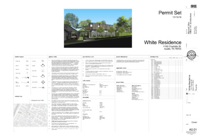
Permit Set 11/15/19 White Residence 1102 Charlotte St. Austin, TX 78703 Pricing Permit Bid 1 2 ETSI ER I C M D A R C H H A E L H.H I T S U G E R E C T S A S T A 2 1 9 4 4 T E FO XE T l a e S 11/15/2019 e r u t c e t i h c r A f O e c i f f O u s H l e a h c i M m o c . e c i f f O u s H 3 0 3 4 . 6 0 7 ) 2 1 5 ( e c i f f O 6 5 7 8 7 s a x e T , n i t s u A d a o R t e n r u B 0 1 9 4 ì n Y m a e T n g s e D i t n a t l u s n o C e c n e d s e R e i t i 3 0 7 8 7 X T , n . t S e t t o l r a h C 2 0 1 1 t c e o r j P h tW i t s u A e S Issue: 11/15/19 Permit Set t e S t i m r e P - - - - - - - - - - x Revisions: Drawing Title Cover Sheet A0.01 This drawing and all copyright therein are the sole and exclusive property of Michael Hsu Office of Architecture. Reproduction or use of this drawing in whole or in part by any means in any way whatsoever without the prior written consent of Michael Hsu Office of Architecture is strictly prohibited. Copyright © 2019 Michael Hsu Office of Architecture symbol legend general notes general notes cont. project description Window Tag 101a Room Tag Keynote 05.04 Elevation 101a A Detail Callout Level 1 0' - 0" Building Section Door Tag Partition Type Level Elevation Spot Elevation 8' - 0" A.F.F Interior Elevation 4 A6.1 2 Material Tag WD-1 Detail Section 1 AX.X / Room 101 1 A3.1 1 A5.1 1 A3.1 1 3 vicinity map 1. 2. 3. 4. 5. 6. 7. 8. 9. 10. 11. 12. 13. 14. 15. 16. All work shall be performed in accordance with all applicable codes; regulations, ordinances and standards having jurisdiction. If there are any questions or conflicts concerning compliance with such codes, ordinances or standards, the contractor is responsible for notifying the designer before proceeding with the work in questions. All necessary permits, licenses, certificates, tests. Etc. shall be procured and paid for by the contractor (or owner if he designates). Refer to specification "General Conditions" section for clarifications on fee responsibilities. Contractor is responsible for checking all contract documents, field conditions and dimensions for accuracy and confirming that the work is buildable as shown and meets all applicable codes before proceeding with construction. If there are and questions regarding these or other coordination issues, the contractor is responsible for obtaining a clarification from the designer before proceeding with the work in question or related work. The contractor shall certify size and location of all required openings for structural, mechanical, electrical and plumbing work and equipment with trades involved. The general contractor and each subcontractor shall be responsible for checking existing conditions at the job site before submitting proposals. Submissions of proposals shall be taken as evidence that such inspections have been made. Claims for extra compensation for work that could have been foreseen by such inspection, whether shown on contract documents or not, shall not be accepted or paid. guaranteed against defective materials and workmanship for a All materials furnished under this contract shall be new unless otherwise noted. All work shall be period of one (1) year after the date of substantial completion or acceptance of the work. The contractor shall repair or replace, at his won expense when ordered to so, all work that may develop defects in material and workmanship within said period of time. All equipment shall be installed in accordance with manufacturer's published recommendations for service intended, as interpreted by the engineer. The installation of all equipment shall be made by experienced craftsmen in a neat, workmanlike manner. All materials, tools, costs and services necessary to completely install all mechanical, electrical, and plumbing work shall be provided by the contractor. Contractor shall be responsible for adequately bracing and protecting all work during construction against damage, collapse and misalignment according to applicable codes, standards, and good construction practices. Contractor shall take proper precautions to protect all existing operations and property adjacent, with which work comes in contact, or over or under which he may transport, hoist, or move materials, equipment, debris, etc. and shall repair satisfactorily all damages caused by him during construction. The contractor shall submit to the designer confirmations or orders, including delivery dates, for all materials and equipment whose timely delivery is required to avoid changes in the construction documents or in the construction schedule. The contractor must submit shop drawings to the designer for approval before proceeding with fabrication. The contractor remains responsible for details and accuracy, for confirming and correlating all quantities and dimensions, for selecting fabrication processes, for techniques or assembly, for performing the work in a safe manner, and for adhering to all applicable codes and standards. Location of all ceiling mounted items in the designer's construction documents have precedence over MEP drawings. Designer shall be notified of any conflicts prior to construction. It is the intent and meaning of the contract documents that the contractor shall provide a mechanical, electrical, and plumbing installation that is complete. All items and appurtenances necessary, reasonably incidental, or customarily included, even though each and every item is not specifically called out or shown in the construction documents shall be provided. All MEP related items should be reviewed by the engineer and may be adjusted pending notice to and approval of the designer. Written dimensions shall have precedence. Do not scale dimensions. If no dimension is listed, contact designer for clarification. All work noted "N.I.C." or "Not in Contract" is to be accomplished by a contractor other then the general contractor and is not to be part of the construction agreement. "Align" as used in these documents shall mean to accurately locate finish faces in the same plane. 17. 18. 19. 20. 21. 22. 23. "Typical" or "Typ." as used in these documents shall mean that the condition is the same or representative for all similar conditions throughout, unless otherwise noted. "Similar" or "Sim." As used in these documents shall mean that the condition is similar to a condition detailed for another location. The contractor shall provide updated record documents of as-built conditions on-site when different from construction documents, and shall provide said documents to designer upon completion of construction. This cover sheet is a master index. Not all symbols/items will be included in drawings. Do not disassemble this set or distribute partial sets to subcontractors. Cover sheet contains data pertaining to all sheets. Refer to additional information for additional general notes, if any. All work shall comply with City of Austin visitability requirements per ordinance 2014013-021 code anaysis Min. Setbacks: Front Yard: Street Side Yard: Int. Side Yard: Rear Yard: Max. Bldg. Height: area totals Zoning: Neighborhood Plan Combining District: Land Use: Min. Lot Size: Max. Dwelling Units House) SF-3 Clarksville Single Family Residential 5,750 sf 2 (1 Main + 1 Guest 25 FT. 15 FT. 5 FT. 10 FT. 35 FT. 1,888 SF First Floor: 1,361 SF Second Floor: Studio 212 SF Existing: 1,312 SF 4,773 SF Conditoned Area: -200 (Garage) Total Conditioned Area: 4,573 SF Unconditioned Floor Area Garage: 459 SF Building Areas Lot Area: Total Building Area: Total Building Coverage: Total Site Impervious: FAR: 11,460 SF 4,584 SF 4,489 SF (39%) 5,025 SF (43%) 0.39 1102 Charlotte St. Austin, TX 78703 The contractor shall verify all coordinate sizes, locations and characteristics of all work and equipment to be furnished by the owner, or others with the manufacturer or supplier before any construction is begun. Conditioned Floor Area The White Residence is a ground-up 3,500 sq. ft. single family house located at 1102 Charlotte Street. There is an existing single family house on the property that we are leaving untouched by our design and it will be used as a guest house. applicable codes 2015 International Building Code* 2015 International Energy Conservation Code* 2015 International Residential Code* *And all applicable City of Austin Amendments project team Design Architect Michael Hsu Office of Architecture 4910 Burnet Rd. Austin, TX 78756 www.hsuoffice.com 512.706.4303 Contact:Joey Rocha Cell #:512.706.4303 Email:hsu@hsuoffice.com Structural Engineer Bufkin Engineering 2309 W. 8th St. Austin, TX 78703 https://www.bufkinengineering.com/ 512-236-8070 Contact:James Bufkin Cell #:512-914-2659 Email:jamesbufkin@bufkinengineering.com Owner Abode Modern Homes 1713 Bluebonnet Lane #B Austin, TX 78704 abodemodernhomes.com 512.848.4547 Contact:Richard White Cell #:512.401.3030 Email:richard@abodemodernhomes.com drawing index Architectural Floor Area Ratio - Level 1 Floor Area Ratio - Level 2 Foundation Plan First Floor Plan First Floor Dimension Plan A0.01 Cover A0.02 General Requirements A0.03 General Requirements A0.04 General Requirements A0.05 ADA Details A0.06 ADA Details A0.07 Site Plan - Survey A0.08 Site Plan A0.09 Building Coverage A0.10 A0.11 A1.00 Basement Plan A1.01 Partition Types (Wood) A1.02 A1.10 A1.11 A1.20 Second Floor Plan A1.21 Second Floor Dimension Plan A1.30 Roof Plan A2.10 A2.20 Second Floor RCP A3.00 Exterior Elevations A3.10 Exterior Elevations A3.12 Exterior Elevations A3.20 Building Sections A3.30 Building Sections A3.40 Building Sections A4.10 Wall Sections A6.00 A6.10 A6.20 A6.30 A6.40 A6.50 A6.60 A7.00 Door Schedule A7.10 Window Details A8.00 Finish Schedule Interior Elevations Interior Elevations Interior Elevations Interior Elevations Interior Elevations Interior Elevations Interior Elevations First Floor RCP = = = N 31°32'36" E 38.13' resub lot 7 MASS ADDITION 85/38D 5' Sewer Esmt Lot 3 Silitt Addition 85/138D (N 30°58' E 57.92') N 31°48'48" E 57.92' N 30°52'00" E 15.90' N 60°20'00" W 10.38' = = (N 30°58' E 57.06') N 31°48'48" E 57.07' carport wood fence = = #80 #79 3.6' 5 2 8 10.2' Silitt Addition Doc# 2004168574 Mel F. Livingston 0.1337 acre 5,825 sq. ft. ) ' 3 1 . 0 1 W " 0 5 5 1 ° 9 5 N ( ' ' 6 2 . 1 1 W " 7 1 ' 6 1 ° 8 5 N . ) ' 6 8 2 8 ( E S A B G N R A E B I ' . 4 8 2 8 W " 0 5 5 1 ° 9 5 N ' t e e r t S h t 1 1 t s e W 5 2 2 85/38D 5' Sidewalk/ P.U.E. Esmt. 522 S 7 ( S 7 ° 7 4 5 4 ° ' 2 1 3 2 ' " W W 2 2 8 . 6 7 . 9 1 ' ) 4 ' 3 2 5 23.76' Lot 2 ' 6 . 0 3 Silitt Addition 85/38D 0.1311 acre 5,713 sq. ft. 5 2 6 drain a g e e a s e m e nt 8 5 / 3 8 D #644 #643 X F.F. 527.3' #645 3 3 6 0 . ' 5 2 5 5 2 4 5 2 3 9.7' TWO STORY BRICK HOUSE #675 1 4.7' #674 wood deck 4 2 5 ' 6 . 4 2 X F.F. 526.4' A/C D E R A T R O M - N O N I E V R D K C R B I 5 2 7 #78 ' S 5 9 ° 3 9 3 2 " E 1 0 2 5 3 . ' S 6 0 ° 2 0 E 1 0 2 ' . 5 7 ' ) = = = = 5 2 9 = = = = = e c n e f d o o w #122 = = #74 #73 #72 " 2 / 1 1 1 - ' 3 1 #75 5 3 0 1 3 5 Lot 1 85/38D 0.1319 acre 5,747 sq. ft. S 6 0 ° 2 0 E 9 7 ' . 3 3 ' ) S 5 9 ° 4 1 ' 2 5 " E 9 7 2 2 . ' vacant lot W ( S 2 1 ° 4 0 ' W ) 9 2 5 S 31°27'46" W 37.42' (S 30°52'10" W 37.27') 525 526 527 528 Radius = 436.50' Arc = 58.12' (58.08') BENCH MARK SURVEY Waterloo Surveyors Inc. PLAT O u s H e r u t c e t i h c r A f O e c i f f O u s H l e a h c i M m o c . e c i f f . 3 0 3 4 6 0 7 ) 2 1 5 ( e c i f f O 6 5 7 8 7 s a x e T , n i t s u A d a o R t e n r u B 0 1 9 4 ì n Y m a e T n g s e D i t n a t l u s n o C TREE LIST: #, TYPE, SIZE 72, ELM 16 73, ELM 9 74, ELM 10 75, ELM 11 76, JUNIPER 13 8 77, ELM 10 78, LIVE OAK 9 79, ELM 9 80, ASH 17 81, ELM 10 122, ELM 13 643, ELM 17 17 644, PECAN 8 645, ELM 12 10 8 674, LIVE OAK 15 15 675, ELM 21 Kindra A. & Kerri Welch Doc# 2006226343 ONE STORY HOUSE ETSI ER I C M D A R C H H A E L H.H I T S U G E R E C T S A S T A 2 1 9 4 4 T E FO XE T l a e S 11/15/2019 e c n e d s e R e i t i 3 0 7 8 7 X T , n . t S e t t o l r a h C 2 0 1 1 t c e o r j P h tW i t s u A e S Issue: 11/15/19 Permit Set t e S t i m r e P - - - - - - - - - - x Revisions: ' S 5 9 ° 3 4 5 9 " E 1 0 9 9 3 . ' " 6 - ' 8 1 Radius = 436.50' Arc = 53.83' Chord = 53.80' (53.84') (53.81') S 33°50'05" W conc. sidewalk Radius = 436.00' Arc = 51.47' Chord = 51.44' N 37°29'13" E 1 Survey 1/8" = 1'-0" Drawing Title THE PROPERTY SURVEYED IS Site Plan - Survey Sheet A0.07 This drawing and all copyright therein are the sole and exclusive property of Michael Hsu Office of Architecture. Reproduction or use of this drawing in whole or in part by any means in any way whatsoever without the prior written consent of Michael Hsu Office of Architecture is strictly prohibited. Copyright © 2019 Michael Hsu Office of Architecture 15' - 0" Street Sideyard Setback D rain a g e E a s e m e nt 02.15 t e e r t S h 1 1 t 02.13 T N E M E S A E E S U C L B U P I Existing Structure N.I.C. " 0 - ' 5 2 k c a b t e S d r a y t n o r F " 0 - ' 0 1 k c a b t e S d r a y k c a B 23.10 23.11 5' - 0" Sideyard Setback 26.06 Portion 1 High Point 529' - 1/8" Proposed Accessory Structure Proposed 2-Story Portion of Residence 01.01 Covered Patio Existing A/C Courtyard Covered Entry *Visitibility Entrance Proposed 1-Story Portion of Residence Open Steel Trellis Above l y a w k a W d e r e v o C Roof Overhead Frontyard Setback 529' - 0" 02.14 32.12 32.19 32.22 04.02 32.20 04.02 32.19 04.02 Charlotte Street 1 Site/Plot Plan 1/8" = 1'-0" Portion 2 High Point 529' - 2 1/4" SITE PLAN KEYNOTES 1. 2. 3. 4. 5. 6. 01.01 02.13 02.14 02.15 04.02 23.10 23.11 26.06 32.12 32.19 32.20 32.22 SITE PLAN GENERAL NOTES clarification. All spot elevations to be verified in field prior to construction. Notify MHOA of any discrepancies. Benchmark to be verified with architect prior to construction. Do not scale the drawings. If a specific dimension is not given, contact MHOA for GC is responsible for protecting and repairing additional damage arising during both demolition phase and new construction phase on existing partitions, finishes, and building elements that are to remain. Tree protection fencing is required for all existing trees 19 inches in diameter (60 inches in circumference) within the limits of construction. Fencing should protect the entire critical root zone (CRZ) area. Fencing is required to be chain-link mesh at a minimum height of five feet. A 6-inch layer of mulch within the entire available root zone area is required for trees which have any disturbance indicated within any portion of the critical root zone. Refer to General Requirements for additional information associated with, but not limited to: submittals, shop drawings, samples, cutting and patching, coordination and staging, protection of work. Existing tree to be removed and replaced with smaller tree to be determined by owner Existing house to remain Existing driveway to remain Existing electrical service Stone river rock pavers Condenser units on concrete pad. Hvac pad Electrical panel New planter with corten steel edging. Fill area with gravel New trees to be chosen by owner Cast in place concrete planter box, general contractor to coordinate plantings and irrigation TREE LEGEND Existing Tree to Be Removed Existing Tree to Be Removed e r u t c e t i h c r A f O e c i f f O u s H l e a h c i M m o c . e c i f f O u s H . 3 0 3 4 6 0 7 ) 2 1 5 ( e c i f f O 6 5 7 8 7 s a x e T , n i t s u A d a o R t e n r u B 0 1 9 4 ì n Y m a e T n g s e D i t n a t l u s n o C ETSI ER I C M D A R C H H A E L H.H I T S U G E R E C T S A S T A 2 1 9 4 4 T E FO XE T l a e S 11/15/2019 e c n e d s e R e i t i 3 0 7 8 7 X T , n . t S e t t o l r a h C 2 0 1 1 t c e o r j P h tW i t s u A e S Issue: 11/15/19 Permit Set t e S t i m r e P - - - - - - - - - - x Revisions: Drawing Title Site Plan Sheet A0.08 This drawing and all copyright therein are the sole and exclusive property of Michael Hsu Office of Architecture. Reproduction or use of this drawing in whole or in part by any means in any way whatsoever without the prior written consent of Michael Hsu Office of Architecture is strictly prohibited. Copyright © 2019 Michael Hsu Office of Architecture 1 2 32' - 2 1/2" 1 A3.20 3 4 5 6 Portion 2 Portion 1 40' - 0" 2 A3.30 1 A3.40 WD-1 WD-3 05.12 01.03 ELEVATION & SECTION GENERAL NOTES 1. 2. 3. 4. Contractor (GC) to field verify all dimensions prior to construction and/or installation of any equipment, accessories, etc. If a discrepancy is identified, notify MHOA immediately. Elevations and building sections are shown for reference only. Refer to Building Plans, Wall Sections and Window Elevations for additional information. Do not scale the drawings. If a specific dimension is not given, contact MHOA for clarification. Refer to General Requirements for additional information associated with, but not limited to: submittals, shop drawings, samples, cutting and patching, coordination and staging, protection of work. T/O Parapet Edge 550' - 7 9/32" ELEVATION KEYNOTES 01.03 Back painted glass per window schedule. 05.12 Steel plate coping on parapet sloping 1/8"=1'0" to perimeter 22.08 Outdoor shower, refer to fixture schedule " 0 - ' 2 3 4 5 . 0 0 ° " 0 - ' 7 1 " 0 - ' 5 1 123b 117c RF-1 MTL-3 109c 111a 109b 110a 101b 6 5 4 3 40' - 0" 2 1 32' - 2 1/2" Portion 1 Portion 2 1 A3.40 2 A3.30 05.12 WD-1 1 A3.20 EQ. EQ. 22.08 TL-3 RF-1 MTL-3 117a 0° 5.0 4 117b MTL-2 108a 103c 103c 103a 103a CNC-2 T/O F.F. @2nd 538' - 5 1/2" B.O. Soffit 536' - 9 3/8" Portion 2 High Point 529' - 2 9/32" Portion 1 High Point 529' - 0 3/32" T/O F.F. @1st 527' - 8 1/8" T/O F.F. @ Master 526' - 8 1/8" T/O Parapet Edge 550' - 7 9/32" T/O F.F. @2nd 538' - 5 1/2" B.O. Soffit 536' - 9 3/8" Portion 2 High Point 529' - 2 9/32" Portion 1 High Point 529' - 0 3/32" T/O F.F. @1st 527' - 8 1/8" T/O F.F. @ Master 526' - 8 1/8" 101b CNC-2 2 West Exterior Elevation 1/4" = 1'-0" " 0 - ' 7 1 " 0 - ' 5 1 1 East Exterior Elevation 1/4" = 1'-0" e r u t c e t i h c r A f O e c i f f O u s H l e a h c i M m o c . e c i f f O u s H . 3 0 3 4 6 0 7 ) 2 1 5 ( e c i f f O 6 5 7 8 7 s a x e T , n i t s u A d a o R t e n r u B 0 1 9 4 ì n Y m a e T n g s e D i t n a t l u s n o C ETSI ER I C M D A R C H H A E L H.H I T S U G E R E C T S A S T A 2 1 9 4 4 T E FO XE T l a e S 11/15/2019 e c n e d s e R e i t i 3 0 7 8 7 X T , n . t S e t t o l r a h C 2 0 1 1 t c e o r j P h tW i t s u A e S Issue: 11/15/19 Permit Set t e S t i m r e P - - - - - - - - - - x Revisions: Drawing Title Exterior Elevations Sheet A3.00 This drawing and all copyright therein are the sole and exclusive property of Michael Hsu Office of Architecture. Reproduction or use of this drawing in whole or in part by any means in any way whatsoever without the prior written consent of Michael Hsu Office of Architecture is strictly prohibited. Copyright © 2019 Michael Hsu Office of Architecture A B C D E F G H I 2 A3.20 GL-2 05.12 01.03 WD-3 WD-1 05.05 05.06 05.07 RF-1 WD-4 125a 117a ELEVATION & SECTION GENERAL NOTES 1. 2. 3. 4. Contractor (GC) to field verify all dimensions prior to construction and/or installation of any equipment, accessories, etc. If a discrepancy is identified, notify MHOA immediately. Elevations and building sections are shown for reference only. Refer to Building Plans, Wall Sections and Window Elevations for additional information. Do not scale the drawings. If a specific dimension is not given, contact MHOA for clarification. Refer to General Requirements for additional information associated with, but not limited to: submittals, shop drawings, samples, cutting and patching, coordination and staging, protection of work. ELEVATION KEYNOTES 1" concrete relief pattern 01.03 Back painted glass per window schedule. 03.06 05.05 Steel trellis, refer to structural 05.06 Painted steel beam, refer to finish schedule 05.07 Paint-grip breakmetal, 22 ga. Min, to match windows 05.12 Steel plate coping on parapet sloping 1/8"=1'0" to perimeter 07.16 Gutter downspout. e r u t c e t i h c r A f O e c i f f O u s H l e a h c i M m o c . e c i f f O u s H . 3 0 3 4 6 0 7 ) 2 1 5 ( e c i f f O 6 5 7 8 7 s a x e T , n i t s u A d a o R t e n r u B 0 1 9 4 101c 2 A3.20 123a 05.12 CNC-2 03.06 03.06 I H G F E D C B A WD-1 05.12 07.16 WD-3 " 0 - ' 2 3 4 5 . 0 0 ° " 0 - ' 5 1 114a CNC-2 110a 108b 111a MTL-3 RF-1 0° 5.0 4 " 0 - ' 2 3 " 0 - ' 7 1 " 0 - ' 5 1 T/O Parapet Edge 550' - 7 9/32" T/O F.F. @2nd 538' - 5 1/2" B.O. Soffit 536' - 9 3/8" Portion 2 High Point 529' - 2 9/32" Portion 1 High Point 529' - 0 3/32" T/O F.F. @1st 527' - 8 1/8" " 4 - ' 1 CNC-2 2 South Exterior Elevation 1/4" = 1'-0" ì n Y m a e T n g s e D i t n a t l u s n o C ETSI ER I C M D A R C H H A E L H.H I T S U G E R E C T S A S T A 2 1 9 4 4 T E FO XE T l a e S 11/15/2019 e c n e d s e R e i t i 3 0 7 8 7 X T , n . t S e t t o l r a h C 2 0 1 1 t c e o r j P h tW i t s u A e S Issue: 11/15/19 Permit Set t e S t i m r e P - - - - - - - - - - x Revisions: Drawing Title Exterior Elevations Sheet A3.10 This drawing and all copyright therein are the sole and exclusive property of Michael Hsu Office of Architecture. Reproduction or use of this drawing in whole or in part by any means in any way whatsoever without the prior written consent of Michael Hsu Office of Architecture is strictly prohibited. Copyright © 2019 Michael Hsu Office of Architecture T/O Parapet Edge 550' - 7 9/32" T/O F.F. @2nd 538' - 5 1/2" B.O. Soffit 536' - 9 3/8" Portion 2 High Point 529' - 2 9/32" T/O F.F. @1st 527' - 8 1/8" T/O F.F. @ Master 526' - 8 1/8" 1 North Exterior Elevation 1/4" = 1'-0"