B.6 - Rocky Cliff House, 802 Barton Boulevard - PLANS — original pdf
Backup
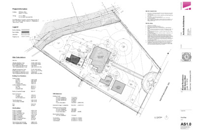
Project Information Address: 802 Barton Blvd Austin, TX 78704 Zoning: SF-3-H, Zilker, South Lamar Combined NPA Legal Description: A portion of Lot 2A, Resubdivision of Lots 1 & 2 South Lund Park, Section 2, a Subdivision in Travis County, Texas. Legend Existing Building New Addition Demolition Property Line Site Calculations Site Area: 56,480.64 SF Allowable Building Cover Existing Building Cover New Addition to Building Cover Total Proposed Building Cover 22,592.26 SF (40%) 4,115.00 SF (7.29%) 1,552.26 SF 5,667.26 SF (10.03%) Allowable Impervious Cover Existing Impervious Cover New Addition to Impervious Cover Total Proposed Impervious Cover 25,416.28 SF (45%) 14,103.21 SF (24.97%) 2,640.25 SF 16,563.46 SF (29.33%) Existing Detached Garage 992.0 SF Building Cover Breakdown Existing House 1st Floor 2nd Floor 3rd Floor Covered Porch Existing Accessory Dwelling 1st Floor 2nd Floor Covered Porch New Pool Pavilion 1st Floor Covered Patio Other Roofed Areas Total Building Area Total Building Coverage Pool Spa Site Breakdown Existing Driveways Existing Sidewalks Existing Uncovered Patio Existing Other Flatwork Addition to Driveway Addition to Sidewalks Addition to Uncovered Patio Addition to Flatwork 2,831.00 SF 1,900.00 SF 790.00 SF 708.00 SF 480.00 SF 480.00 SF 96.00 SF 718.64 SF 725.62 SF 108.00 SF 8,933.26 SF 5,667.26 SF 838.38 SF 55.78 SF 4,085.30 SF 2,465.20 SF 1,396.51 SF 2,041.20 SF 506.85 SF 0.00 SF 357.57 SF 43.57 SF Total Existing Site Coverage Total Proposed Site Coverage 9,988.21 SF 10,896.20 SF P R O P E R T Y L I N E P R O P E R T Y L I N E 1 0 ' R E A R S E T B A C K 16" CEDAR ELM O P R P E R T Y LIN E 1 0' R E A R S E T B A C K 5' SID E Y A R D S P R O P E R T E T B A C K Y LIN E 16" CEDAR ELM " 3 8 6'-1 2 NEW POOL DECK 9'-0" 1'-7" 1 NEW POOL DECK " 1 4 7'-5 2 1 " VIF 7 8 7'-5 1 POOL BATH NEW 1-STORY POOL PAVILION (NOT A DWELLING UNIT) P O O L E Q UIP. 56'-7" 68'-103 4" 4'-6" EXISTING POOL EXISTING SPA 1'-7" 1 2'-0" PLANTER 2 2'-0" 6'-0" PLANTER 6'-6" R E T N A L P DIVING BOARD 2 ' - 0 " 6'-0" R E T N A L P TIO A D P E R E V O C 19'-8" 5'-0" OUTDOOR COVERED DINING 6'-0" 9'-0" 4 3 STORY EXISTING ROCK & WOOD FRAME HOUSE 1/2 CRZ 1/4 CRZ 21" CEDAR ELM 1/2 CRZ 1/4 CRZ 19" CEDAR ELM H C R O D P E R E V O C 1/4 CRZ 20" CEDAR ELM 1/2 CRZ 13" CEDAR ELM 5' P. P R O P E R T Y L I N E 5 ' S I D E Y A R D S E T B A C K 1/2 CRZ 1/4 CRZ 49" LIVE OAK " VIF 1 4 2'-7 3 12'-0" T N E M E S A Y E TILIT U A/C A/C A/C 19" PECAN 1/4 CRZ 1/2 CRZ 8 42'-0" 5' SID E Y A R N E W D RIV E W A Y D S E T B A C K P R O P E R T Y LIN E 3 14" CEDAR ELM EXTG W ALK W AY 1/2 CRZ 1/4 CRZ 19" PECAN 2 STORY EXISTING ROCK HOUSE DRIVEWAY 4 1 STORY EXISTING ROCK DETACHED GARAGE 20'-0" M BUILDIN ATERIALS AREA G 5'-0" 1 K C A B T E T S N O R 5' F 2 17" PALM 11" PALM E Y LIN T R E P O R P DRIVEWAY P R O P E R T Y LIN E CHINKAPIN 12" OAK DRIVEWAY FAR Calculations Existing House: 1st Floor conditioned 2nd Floor conditioned 3rd Floor conditioned Attic Porch (- Exemption) 2,831.00 SF 1,900.00 SF 790.00 SF 144.00 SF 708.00 SF (-200.00 SF) Detached Garage (- Exemption) 992.00 SF (-450.00 SF) Existing Accessory Building: 1st Floor conditioned 2nd Floor conditioned Porch (- Exemption) 480.00 SF 480.00 SF 96.00 SF (-96 SF) New Accesory Building: 1st Floor conditioned 718.64 SF Total Existing: Total Proposed: Total Allowed: 7,675.00 SF (13.59%) 8,393.64 SF (14.86%) 22,592.26 SF (.4 max) 1. 2. 3. 5. 6. 7. 1. 2. 3. 4. 5. 6. 7. 8. 9. 10. Site Plan General Notes: The dimensions on this sheet are based off of the face of foundation and the property line. All spot elevations to be verified in field prior to construction. Notify Activate Architecture of any discrepancies. Refer to appropriate sheet and/or schedule for additional information/detail regarding items shown herein. Keynotes located on this sheet are for this sheet only. Do not scale the drawings. If a specific dimension is not given, contact Activate Architecture for clarification. Refer to Sheet A0.1-General Conditions for additional information associated with, but not limited to: submittals, shop drawings, samples, cutting and patching, coordination and staging, protection of work. Site Plan Notes: Awning above, shown dashed. Existing pool, spa, and diving board to remain. New driveway to match existing, provide expansion joint. Existing building to remain. Contractor to take all precautions to protect building from damage. Refer to City of Austin's Land Development Code Section 25-8 Subchapter B, Article 1 and Enviornmental Criteria Manual Section 3.5.2 for details about the Tree Preservation Criteria. The following may not be placed within ½ Critical Root Zones: Access routes, Dumpster, and Spoils placement. The following may not be placed within Full Critical Root Zones: Portable toilet, Concrete washout, and Paint washout. Provide chain-link mesh fencing at a minimum height of five feet around the entire ½ Critical Root Zone. When the tree protection fencing cannot incorporate the entire ½ Critical Root Zone, an eight inch layer of mulch within the entire available root zone area is required for all trees which have any disturbance indicated within any portion of the Critical Root Zone. Foot traffic is considered a root zone disturbance, as well. Provide 2x4 or greater size planks (6’ tall minimum) to be strapped securely around protected trees trunks and root flares when protective fencing does not incorporate the entire ½ CRZ for any reason at any time in the project. Concrete line pump: If a line pump will be used, wrap connections of concrete line pump with plastic to prevent concrete slurry from leaching into ground and near roots of trees. Concrete truck: If heavy equipment will be rolling over any area of the full CRZ of protected trees, provide 3/4" plywood over 2x4 lumber over 12″ layer of mulch to bridge over the roots and prevent soil/root compaction. After construction is completed, spread mulch around site to leave a max layer of 3″ within root zones 5 ' S I D E Y A R D S E T B P A R C K O P E R T Y L I N E G U Y W I R E E A S E M E N T K C A B T E T S N O R 5' F 2 w DRIVEWAY 0') D (5 R A V E L U O N B O T R A B N Scale:1 Site Plan 1/16"=1'-0" e r u t c e t i h c r A e t a v i t c A 1 1 4 # t t S h 7 1 W 6 0 6 1 0 7 8 7 s a x e T , n i t s u A . 8 1 4 0 7 0 7 1 6 5 . m o c . t h c r a e a v i t c a w w w . e r u t c e t i h c r A g n i t a v i t c A r e n g s e D i t n a t l u s n o C l a e S 9 1 0 2 r e b m e v o N 6 1 , t e S t i m r e P i e c n e d s e R d n a r B l d v B n o t r a B 2 0 8 4 0 7 8 7 , X T , n i t s u A t e S j t c e o r P Issue: Drawing Title Site Plan Sheet AS1.0 This drawings and all copyright therein are the sole and exclusive property of Activate Architecture. Reproduction or use of this drawing in whole or in part by any means in any way whatsoever without the prior written consent of Activate Architecture is strictly prohibited. Copyright © 2018 Activate Architecture POOL DECK PLANTER DIVING BOARD PLANTER POOL 22 21 SPA 3 18 23 Typ. 19 20 PLANTER LC COLUMN 3'-3" 12'-0" 5'-11" LC COLUMN POOL DECK 1 A3.0 16'-33 4" 23 Typ. 6'-65 8" LC COLUMN 8'-95 8" 2'-3" 1'-6" " 58 2 - ' 4 " 38 9 - ' 3 " 6 - ' 2 " 14 1 1 - ' 2 1 " 6 - ' 9 " 6 - ' 2 " 6 - ' 1 " 14 5 - ' 6 3 3 . 0 3 A 11 2 30 11 24 Typ. PLANTER 11 24 FD FD 14 4 23 B Above C Above D Above E Above F Above FD 35 4 C U / F E R C U / E C I E T T E N E H C T K I 40 36 15 10 17 40 32 13 34 " 12 9 - ' 1 " 12 8 - ' 3 e v o b A G " 4 - ' 8 H " 12 6 - ' 6 11 39 OUTDOOR DINING FD 10 U/C REF 15 8 GRILL " 12 8 - ' 1 " 3 - ' 1 11 13 Typ. 11 2 6 4 8 PING PONG FD 2 e v o b A A 38 39 16 5 3 4 15 1 8'-0" 19 40 " 9 - ' 1 6 BENCH BATH 17 FD FD OUTDOOR SHOWER " 0 - ' 4 LIVING 31 V T BENCH BENCH 7'-25 8" 4 A3.0 7'-25 8" 22'-8" 58'-7" 7'-25 8" 12 7 K Above J Above I Above 2'-4" STAGING 30 5 14 37 17 9 1 17 2 30 25 1'-11" 4'-5" 12'-9" 11'-4" 3'-6" 2'-0" 9'-0" 29 28 NN Scale:1 Floor Plan 1/4"=1'-0" 10" " 6 - ' 9 " 6 - ' 1 " 6 - ' 1 " 0 - ' 5 13 26 27 7 33 30 27 R E T N A L P R E T N A L P " 18 9 - ' 1 2 " 0 - ' 3 2 . 0 3 A " 0 - ' 3 1'-0" TYP 1'-0" TYP Floor Plan General Notes: 1. 2. 3. 4. 5. 6. 7. 8. The dimensions on this sheet are to face of stud and/or masonry, centerline of column/beam, and face of awning. GC to field verify all dimensions prior to construction and/or installation of any equipment, accessories, etc. If a discrepancy is identified, please notify Activate Architecture immediately. GC to provide portable fire extinguishers as required by local code. Refer to appropriate sheet and/or schedule for additional information/detail regarding items shown herein. Keynotes located on this sheet are for this sheet only. Do not scale the drawings. If a specific dimension is not given, contact Activate Architecture for clarification. Refer to Sheet A0.1-General Conditions for additional information associated with, but not limited to: submittals, shop drawings, samples, cutting and patching, coordination and staging, protection of work. Install all products per manufacturer's recommendations. Floor Plan Notes: 1. 2. 3. 4. 5. 6. 7. 8. 9. 10. 11. 12. Isokern Fireplace, install per manufacturer's recommendations. See Interior Elevations and Structural. Awning above, shown dashed. Shower fixtures per Project Manual. Stucco wall per Finish Schedule. Western red cedar wood framing with WRC horizontal slats at outdoor shower enclosure. Sealant per Finish Schedule. Metal frame with horizontal wood screen per Finish Schedule. Metal frame and attachments per Structural. Niche in stone wall with wood header per Structural. Finish per Finish Schedule. Plumbing fixtures per Project Manual. Fireplace metal flue, shown dashed. Countertop per Finish Schedule. Steel column per Structural. Painted per Finish Schedule. Door with horizontal wood screen per Finish Schedule. Frame and attachments per Structural. Stone wall per Finish Schedule. Cabinetry above shown dashed. See Interior Elevations. Cabinetry per Interior Elevations. Concrete foundation per Structural. Polished finish per Finish Schedule. Furniture and furnishings per Owner. Existing pool coping to be replaced with new paver per Finish Schedule. Existing spa to remain, Contractor to ensure protection during construction. Existing pool to remain, Contractor to ensure protection during construction. Stone landscaping per Landscape Architect. Steel plate landscaping per Landscape Architect. Concrete steps per Finish Schedule. Existing home to remain, Contractor to ensure protection during construction. 13. 14. Window in western red cedar framing, to match adjacent finishes per Finish Schedule. 15. 16. Glass frameless shower enclosure. 17. 18. 19. 20. 21. 22. 23. 24. 25. 26. 27. New planters per Landscape Architect. 28. 29. 30. 31. Existing pool equipment to remain. Setback line shown dashed. Concrete foundation and flatwork per Structural. Broom finish per Finish Schedule. Stone veneer over Isokern fireplace and framing. Provide clearances per manufacturer and IRC 2015 Chapter 10. TV provided by owner. Contractor to verify mounting height and location of electrical/ cable connections in field with owner and architect. Large single stone threshold set flush with concrete floor, per Finish Schedule. 33. 34. Opening in stone wall with wood header per Structural. Finish per Finish Schedule. 35. Wall framing and 1 2" plywood for pocket at sliding glass door. Provide plywood at interior 32. pocket, painted black. Maintain minimum clear for pocket per door manufacturer. Contractor to verify per door manufacturer. Phantom screen recessed into wall installed per manufacturer's recommendations, coordinate in field with architect. Teak wood slats at outdoor shower floor, recessed into and flush with adjacent concrete floor. Per Finish Schedule. Tile floor at shower recessed in and flush with adjacent concrete floor, sloped to drain. Per Finish Schedule. ALTERNATE: Provide alternate pricing for skylights, shown dashed. Refer to Window Schedule. Stucco surface at interior walls to match exterior finish, per Finish Schedule. 36. 37. 38. 39. 40. e r u t c e t i h c r A e t a v i t c A 1 1 4 # t t S h 7 1 W 6 0 6 1 0 7 8 7 s a x e T , n i t s u A . 8 1 4 0 7 0 7 1 6 5 . m o c . t h c r a e a v i t c a w w w . e r u t c e t i h c r A g n i t a v i t c A r e n g s e D i t n a t l u s n o C l a e S 9 1 0 2 r e b m e v o N 6 1 , t e S t i m r e P i e c n e d s e R d n a r B l d v B n o t r a B 2 0 8 4 0 7 8 7 , X T , n i t s u A t e S j t c e o r P Issue: Drawing Title Floor Plan Sheet A1.0 This drawings and all copyright therein are the sole and exclusive property of Activate Architecture. Reproduction or use of this drawing in whole or in part by any means in any way whatsoever without the prior written consent of Activate Architecture is strictly prohibited. Copyright © 2018 Activate Architecture Elevation & Section General Notes: 1. 2. 3. 4. 5. 6. 7. 8. 9. The dimensions on this sheet are based off of the face of finish material or masonry. All dimensions are to face of finish material, edge of awning, or centerline of support, unless otherwise noted. Contractor (GC) to field verify all dimensions prior to construction and/or installation of any equipment, accessories, etc. If a discrepancy is identified, notify Activate Architecture immediately. Elevations are shown for reference only. Refer to Building Plans, Sections, Wall Sections and Window Elevations for additional information. All glass to be tempered in areas required by applicable code. Refer to appropriate sheet and/or schedule for additional information/detail regarding items shown herein. Keynotes located on this sheet are for this sheet only. Do not scale the drawings. If a specific dimension is not given, contact Activate Architecture for clarification. Refer to Sheet A0.1-General Conditions for additional information associated with, but not limited to: submittals, shop drawings, samples, cutting and patching, coordination and staging, protection of work. Install all products per manufacturer's recommendations. Asphalt shingle roof per Finish Schedule. Brake metal fascia per Finish Schedule. Exterior shower fixtures per Project Manual. Door per Door Schedule. Stucco per Finish Schedule. Wood frame wall with horizontal wood screen per Finish Schedule. Stone walls shown dashed. Window per Window Schedule. Fireplace metal flue, install per manufacturer. Stainless Steel cabinetry and quartz countertop per Finish Schedule. Steel column per Structural. Painted per Finish Schedule. Door at wood frame with horizontal wood screen to match adjacent per Finish Schedule. Stone wall per Finish Schedule. Sliding glass door per Door Schedule. 1. 2. 3. 4. 5. 6. 7. 8. 9. 10. 11. 12. 13. 14. 15. Metal panel insert above door, color to match window frame. 16. 17. 18. Gutter to connect to scupper/ downspout. 19. Open to beyond. 20. 21. Wood shelving with concealed supports per Finish Schedule. install per manufacturer. GC Awning, framing per Structural. Brake metal fascia per Finish Schedule. Stucco soffit per Finish Schedule. Brake metal and drip edge around perimeter per RCP. Stainless Steel grill and vent hood per Project Manual. to provide blocking in wall framing as required. Brake metal cover to match window frames per Finish Schedule. Tile per Finish Schedule. Cabinetry beyond wall shown dashed. See Interior Elevations. 22. 23. 24. 25. Wood/ timber header per Structural. Finish per Finish Schedule. 26. Wood screen shown dashed. 27. Metal frame wall with horizontal wood screen per Finish Schedule. Frame and attachments per Structural. Brake metal detail at base of stucco walls per Details. Brake metal edge at soffit with metal channel drip edge per Details. Light fxture per RCP and Fixture Schedule. Cast stone cap at top of stone walls, to match color of stone per Finish Schedule. Fireplace beyond, shown dashed. 28. 29. 30. 31. 32. STU-1 5 Typ. 3 8 Typ. MTL-3 9 MTL-2 ASP-1 8 Typ. 2 Typ. 1 MTL-1 11 31 Typ. " 2 - ' 4 1 " 0 - ' 8 " 0 - ' 8 19 " 6 - ' 8 Elevation Notes: 27 11 Typ. WD-1 MTL-1 28 6 MTL-2 WD-1 26 WD-1 4 5 6 STU-1 WD-1 32 28 Typ. 5 Typ. MTL-2 STU-1 13 ST-1 13 ST-1 Scale:4 South Elevation 1/4"=1'-0" MTL-2 16 31 Typ. WD-2 ASP-1 MTL-2 MTL-2 MTL-2 25 1 22 8 Typ. 2 15 MTL-2 MTL-2 15 2 MTL-2 22 ASP-1 1 8 Typ. MTL-2 16 MTL-3 9 1.5 :12 MTL-4 18 MTL-4 18 " 0 - ' 0 "1 6 - ' 8 19 " 0 - ' 0 1 " 0 - ' 8 " 0 - ' 0 1 " 0 - ' 8 " 6 - ' 8 " 0 - ' 0 1 " 6 - ' 8 13 ST-1 11 MTL-1 5 11 STU-1 MTL-1 14 Typ. 4 28 4 Typ. 26 5 Typ. 12 6 MTL-2 WD-1 STU-1 WD-1 WD-1 6 5 28 13 10 Typ. Typ. WD-1 STU-1 MTL-2 ST-1 MT-5 23 TL-1 8 5 28 4 11 5 Typ. STU-1 MTL-2 MTL-1 STU-1 11 MTL-1 7 ST-1 Scale:3 West Elevation 1/4"=1'-0" Scale:2 East Elevation 1/4"=1'-0" MTL-2 STU-1 29 17 Typ. Typ. ST-1 13 MTL-2 MTL-2 16 22 8 Typ. MTL-3 9 MTL-2 22 8 Typ. MTL-2 ASP-1 STU-1 2 1 17 Typ. MTL-1 11 MTL-2 29 Typ. MTL-3 9 WD-2 21 1.5 :12 " 6 - ' 3 12 I F V " 1 - ' 1 1 " 0 - ' 8 31 Typ. " 2 - ' 4 1 " 6 - ' 8 19 13 ST-1 11 23 20 10 24 28 5 11 MTL-1 TL-1 Typ. MTL-5 Typ. MTL-2 STU-1 MTL-1 14 Typ. 11 MTL-1 14 Typ. 28 Typ. 5 Typ. MTL-2 STU-1 27 WD-1 Scale:1 North Elevation 1/4"=1'-0" e r u t c e t i h c r A e t a v i t c A 1 1 4 # t t S h 7 1 W 6 0 6 1 0 7 8 7 s a x e T , n i t s u A . 8 1 4 0 7 0 7 1 6 5 . m o c . t h c r a e a v i t c a w w w . e r u t c e t i h c r A g n i t a v i t c A r e n g s e D i t n a t l u s n o C l a e S 9 1 0 2 r e b m e v o N 6 1 , t e S t i m r e P i e c n e d s e R d n a r B l d v B n o t r a B 2 0 8 4 0 7 8 7 , X T , n i t s u A t e S j t c e o r P Issue: Drawing Title Exterior Elevations Sheet A3.0 This drawings and all copyright therein are the sole and exclusive property of Activate Architecture. Reproduction or use of this drawing in whole or in part by any means in any way whatsoever without the prior written consent of Activate Architecture is strictly prohibited. Copyright © 2018 Activate Architecture