Item 18: Energy Code Article 12 4 of 4 — original pdf
Backup
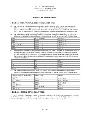
TITLE 25. - LAND DEVELOPMENT. CHAPTER 25-12. - TECHNICAL CODES. ARTICLE 12. ENERGY CODE. ARTICLE 12. ENERGY CODE. § 25-12-261 INTERNATIONAL ENERGY CONSERVATION CODE. (A) The International Energy Conservation Code, 2024 Edition, published by the International Code Council ("2024 International Energy Conservation Code") and Appendices CG, CH, CI, CJ, RE, RF, RJ, and RK, are adopted and incorporated by reference into this section with the deletions and amendments in Subsections (B), (C), and (D) and Section 25-12-263 (Local Amendments to the International Energy Conservation Code). (B) The following commercial provisions of the 2024 International Energy Conservation Code are deleted. A subsection contained within a deleted section or subsection is not deleted, unless specifically listed below: (C) For purposes of commercial energy efficiency compliance with ASHRAE standards, as allowed under the 2024 International Energy Conservation Code, the following provisions of the 2022 edition of ASHRAE standard 90.1 (ASHRAE 90.1-2022), published by the American Society of Heating, Refrigeration, and Air-Conditioning Engineers, are deleted. A subsection contained within a deleted section or subsection is not deleted, unless specifically listed below: C201.3 C402.4 C402.5.3 Table C405.13.2 C405.15.1 CG101.2.1 Table CG101.2.1 CG101.2.2 CG101.2.5 CH103.1.1.2 CH103.1.2.1 CH103.1.2.3 2.2 4.2.1.1 5.5.3.1.4 5.5.4.1 6.5.10 6.7.3.2 7.7.3.2 7.9.1 8.4.3.1 8.7.3.1 R202 definition of "Residential Building" R402.1.2 Table R402.1.2 R402.1.3 Table R402.1.3 R402.3 R402.5.1.2 R402.5.1.3 R402.6 R403.3.7 R403.3.8 Table R403.3.8 R403.3.9 § 25-12-262 CITATIONS TO THE ENERGY CODE. CH103.1.3.1 CH103.1.3.2 CH103.1.4.1 CH103.1.4.2 CI101.1 CI102.1 9.4.1 10.5.1.1 10.7.3.1 G2.4.2 Table R405.2 Table R405.4.2(1) Table R406.2 R503.1.1.1 RJ101.1 RK101.1 (D) The following residential provisions of the 2024 International Energy Conservation Code are deleted. A subsection contained within a deleted section or subsection is not deleted, unless specifically listed below: R402.5.1.2.1 R403.6.3 In the City Code, "Energy Code" means the 2024 International Energy Conservation Code adopted by Section 25-12-261 (International Energy Conservation Code) and as amended by Section 25-12-263 (Local Amendments to the International Energy Conservation Code). In this article, "this code" means the Energy Code. Page 1 of 44 § 25-12-263 LOCAL AMENDMENTS TO THE INTERNATIONAL ENERGY CONSERVATION CODE. (A) The following provisions are local amendments to the commercial provisions of the 2024 International Conservation Code. Each provision in this subsection is a substitute for an identically numbered provision deleted by Section 25-12-261(B) or an addition to the 2024 International Energy Conservation Code. C201.3 Terms defined in other codes. Terms not defined in this code that are defined in the Building Code, Electrical Code, Fire Code, Mechanical Code, Plumbing Code, Residential Code, and Chapter 25-12, Article 3 (Flood Hazard Areas) have the meaning ascribed to them in those codes. C402.2.8 Insulation encapsulation requirement. Insulation (including but not limited to loose fill, spray applied cellular fiber insulation as well as other blanket and batts insulation) installed in assemblies more than 60 degrees from the horizontal must be in substantial contact with an air barrier on all sides. Exception: Air impermeable insulation. Air impermeable insulation is defined as: A material having an air permeance equal to or less than 0.02 L/s-m2 at 75 Pa pressure differential tested according to ASTM E2178 or E283. C402.4 Roof solar reflectance and thermal emittance. Low slope roofs directly above cooled conditioned spaces in Climate Zones 0 through 3 shall comply with one or more of the options in Table C402.4. Exceptions: The following roofs and portions of roofs are exempt from the requirements of Table C402.4: 1. Portions of the roof that include or are covered by the following: 1.1. Photovoltaic systems or components. 1.2. Solar air or water-heating systems or components. 1.3. Vegetative roofs or landscaped roofs. 1.4. Above-roof decks or walkways. 1.5. Skylights. 1.6. HVAC systems and components, and other opaque objects mounted above the roof. 1.7. Repairs to roof surfaces when the repair does not exceed the lesser of 50% of the roof surface or 20 squares (2,000 sq. ft.). 2. 3. 4. Portions of the roof shaded during the peak sun angle on the summer solstice by permanent features of the building or by permanent features of adjacent buildings. Portions of roofs that are ballasted with a minimum stone ballast of 17 pounds per square foot [74 kg/m2 ] or 23 psf [117 kg/m2 ] pavers. Roofs where not less than 75 percent of the roof area complies with one or more of the exceptions to this section. Roof surfaces with an incline greater than 2 units vertical in 12 units horizontal shall incorporate a roof material having a minimum reflectance of 0.35 or a minimum initial SRI of 29. C402.5.3 Maximum U-factor and SHGC. The maximum U-factor and solar heat gain coefficient (SHGC) for fenestration shall be as specified in Table C402.5. The window projection factor shall be determined in accordance with Equation 4-4. (Equation 4-4). PF = A/B where: PF = Projection factor (decimal). Page 2 of 44 A = Distance measured horizontally from the furthest continuous extremity of any overhang, eave or permanently attached shading device to the vertical surface of the glazing. B = Distance measured vertically from the bottom of the glazing to the underside of the overhang, eave or permanently attached shading device. Where different windows or glass doors have different PF values, they shall each be evaluated separately. Exception: Where windows are required to comply with the visible transmittance (VT) requirement outlined in section 3.2.2.E, Glazing and Façade Relief on Building Facades, of the City of Austin's Subchapter E, Design Standards and Mixed Use ordinance, the solar heat gain coefficient (SHGC) requirement shall not apply. Instead, the window shall have a projection factor (PF) ≥ 0.5. C402.8 Commercial Solar Ready (Mandatory). A designated zone must be identified on the construction documents as "Reserved for Future Solar Installation". This identified "Solar-Ready Zone" must be located within the Potential Solar Area (defined below), free from obstructions such as, but not limited to, vents, pipes, ducts, and other equipment and must comply with access, pathway, smoke ventilation, spacing, and other requirements of the City of Austin Land Development Code. Exceptions: Potential Solar Area of less than 2,000 square feet (185.8 square meters). High hazard buildings (Group H). Buildings located within the downtown network, as identified by Austin Energy. Buildings equipped with on-site renewable energy systems in accordance with Section C405.15 or C406.3.1. C402.8.1 Solar-Ready Zone area. The size of the Solar-Ready Zone must be at least half the Potential Solar Area. Potential Solar Area is calculated as the gross rooftop area minus the Affected Area. Affected Area means the following areas: Areas of the roof that are shaded for at least 50% of annual daylight hours. Areas of the roof that are not Low-Sloped Roof that are oriented from 300° northwest, north to 90° east. Gross area of all skylights. Area of rooftop equipment and required access paths. Areas of roofs used for helicopter landing or for rooftop parking. Green roofs and occupied rooftop areas. Areas required by City Code to not contain solar equipment. No part of the Solar-Ready Zone can be in an Affected Area. The designated Solar-Ready Zone and the Potential Solar Area can be made up of multiple non-contiguous areas. Each sub-area must be at least 80 square feet (7.432 square meters) and must be a rectangle the short side of which measures at least 6 feet (1.83 meters). C402.8.2 Structural loads. Areas of the roof that are part of the Solar-Ready Zone must have structural design loads for roof dead load and roof live load clearly indicated on the construction documents. C402.8.3 Equipment location and interconnection pathway. The construction documents must indicate a location for inverters and metering equipment and a pathway for routing of conduit from the Solar-Ready Zone to the point of interconnection with the electrical service. C402.8.4 Electrical distribution system. The Building's electrical service distribution system must have reserved space to allow for the future installation of solar electric and must be permanently marked as "For Future Solar Electric". 1. 2. 3. 4. 1. 2. 3. 4. 5. 6. 7. Page 3 of 44 C403.7.10 Ventilation filtration and filtration of return air. Ventilation systems shall incorporate filtration having a minimum efficiency reporting value (MERV) rating of 6 or greater. All return air as well as all air that is heated, cooled, or humidity controlled must be drawn through the air filtration system. TABLE C405.13.2 ELECTRICAL ENERGY USE CATEGORIES LOAD CATEGORY DESCRIPTION OF ENERGY USE Total HVAC system Interior lighting Exterior lighting Plug loads Process load Electric vehicle charging Heating, cooling and ventilation, including but not limited to fans, pumps, boilers, chillers and water heating. Energy used by 120-volt equipment, or by 208/120-volt equipment that is located in a building where the main service is 480/277-volt power, is permitted to be excluded from total HVAC system energy use. Lighting systems located within the building. Lighting systems located on the building site but not within the building. Devices, appliances and equipment connected to convenience receptacle outlets. Any single load that is not included in an HVAC, lighting or plug load category and that exceeds 5 percent of the peak connected load of the whole building, including but not limited to data centers, manufacturing equipment and commercial kitchens. Electric vehicle charging loads that are powered through the building's electrical service. Building operations and other miscellaneous loads The remaining loads not included elsewhere in this table, including but not limited to vertical transportation systems, automatic doors, motorized shading systems, ornamental fountains, fireplaces, swimming pools, spas and snow-melt systems. Electric hot water heating for uses other than space conditioning Electricity used to generate hot water. Exception: Electric water heating with design capacity that is less than 10 percent of the building service rating. 1. 2. 3. C405.15.1 On-site renewable energy systems. Buildings shall be provided with on-site renewable electricity generation systems with a direct current (DC) nameplate power rating of not less than 0.75 watts per square foot (8.1 W/m2) multiplied by the sum of the gross conditioned floor area of all floors, not to exceed the combined gross conditioned floor area of the three largest floors. Exceptions: The following buildings or building sites shall comply with Section C405.15.2: A building site located where an unshaded flat plate collector oriented toward the equator and tilted at an angle from horizontal equal to the latitude receives an annual daily average incident solar radiation less than 1.1 kBtu/ft2 per day (3.5 kWh/m2/day). A building where more than 80 percent of the roof area is covered by any combination of permanent obstructions such as, but not limited to, mechanical equipment, vegetated space, access pathways or occupied roof terrace. Any building where more than 50 percent of the roof area is shaded from direct-beam sunlight by natural objects or by structures that are not part of the building for more than 2,500 annual hours between 8:00 a.m. and 4:00 p.m. Page 4 of 44 4. 5. 6. 7. 8. 3. 4. 8. 9. A building with gross conditioned floor area less than 5,000 square feet (465 m2) A building with Potential Solar Area of less than 2,000 square feet (185.8 square meters). Alterations. High hazard buildings (Group H). Buildings located within the downtown network, as identified by Austin Energy. CG101 Definitions. LOW POWER LEVEL 2 ELECTRIC VEHICLE (EV) CHARGING RECEPTACLE. A 208/240 Volt 20-ampere minimum branch circuit and a receptacle. CG101.2.1 Quantity. The number of required electric vehicle (EV) spaces, EV capable spaces and EV ready spaces shall be determined in accordance with this section and either Table CG101.2.1 or Table CG101.2.2 based on the total number of automobile parking spaces and shall be rounded up to the nearest whole number. For R-2 buildings, the Table CG101.2.1 or Table CG101.2.2 requirements shall be based on the total number of dwelling units or the total number of automobile parking spaces, whichever is less. 1. Where more than one parking facility is provided on a building site, the number of required automobile parking spaces required to have EV power transfer infrastructure shall be calculated separately for each parking facility. 2. Where one shared parking facility serves multiple building occupancies, the required number of spaces shall be determined proportionally based on the floor area of each building occupancy. Installed electric vehicle supply equipment installed spaces (EVSE spaces) that exceed the minimum requirements of this section may be used to meet the minimum requirements for EV ready spaces and EV capable spaces. Installed EV ready spaces that exceed the minimum requirements of this section may be used to meet the minimum requirements for EV capable spaces. 5. Where the number of EV ready spaces allocated for R-2 occupancies is equal to the number of dwelling units or to the number of automobile parking spaces allocated to R-2 occupancies, whichever is less, requirements for EVSE spaces for R-2 occupancies shall not apply. 6. Requirements for a Group S-2 parking garage shall be determined by the occupancies served by that parking garage. Where new automobile spaces do not serve specific occupancies, the values for Group S-2 parking garage in Table CG101.2.1 shall be used. 7. Group S-2 parking garages with no less than 50% long term parking spaces shall provide no less than 10% EV capable spaces. Long term parking spaces are considered as parking spaces where users generally park for more than 8 hours at a time, including overnight, at places such as airports, transit hubs, etc. The installation of each DCFC EVSE shall be permitted to reduce the minimum number of required EV capable spaces without EVSE or EVCS with Level 2 EVSE by five and reduce proportionally the required electrical load capacity to the service panel or subpanel. The installation of two Low Power Level 2 EV charging receptacles shall be permitted to reduce the minimum number of required EV capable spaces without EVSE in Table CG101.2.1 by one in Group R-1 and Group R-2 occupancies. Exception: Parking facilities serving occupancies other than R2 with fewer than 10 automobile parking spaces. TABLE CG101.2.1 REQUIRED EV POWER TRANSFER INFRASTRUCTURE OCCUPANCY EVSE SPACES EV READY SPACES EV CAPABLE SPACES Page 5 of 44 Group A Group B Group E Group F Group H Group I Group M Group R-1 Group R-2 Group R-3 and R-4 Group S exclusive of parking garages Group S-2 parking garages 0% 0% 0% 0% 0% 0% 0% 0% 0% 0% 0% 0% 0% 0% 0% 0% 0% 0% 0% 5% 5% 0% 0% 0% 10% 30% 30% 5% 0% 30% 30% 35% 35% 5% 0% 30% REQUIRED EV POWER TRANSFER INFRASTRUCTURE – POWER ALLOCATION METHOD TABLE CG101.2.2 TOTAL NUMBER OF ACTUAL PARKING SPACES MINIMUM TOTAL kVA @ 6.6 kVA 0 - 9 10 - 25 26 – 50 51 – 75 76 – 100 101 – 150 151 – 200 201 and over 0 26.4 52.8 85.8 112.2 165 231 20 percent of actual parking spaces x 6.6 TOTAL kVA REQUIRED IN ANY COMBINATION OF EV CAPABLE,3,4 LOW POWER LEVEL 2, LEVEL 2,1,2 OR DCFC 0 26.4 52.8 85.8 112.2 165 231 Total required kVA = P x .20 x 6.6 Where P = Parking spaces in facility 1. Level 2 EVSE @ 6.6 kVA minimum. 2. At least one Level 2 EVSE shall be provided. 3. Maximum allowed kVA to be utilized for EV capable spaces is 75 percent. 4. If EV capable spaces are utilized, they shall meet the requirements of section CG101.2.2. CG101.2.2 EV capable spaces. Each EV capable space used to meet the requirements of Section CG101.2.1 shall comply with the following: 1. 2. 3. 4. A continuous raceway or cable assembly shall be installed between an enclosure or outlet located within 3 feet (914 mm) of the EV capable space and electrical distribution equipment. Installed raceway or cable assembly shall be sized and rated to supply a minimum circuit capacity in accordance with Section CG101.2.5. The electrical distribution equipment to which the raceway or cable assembly connects shall have dedicated overcurrent protection device space and electrical capacity to supply a calculated load in accordance with Section CG101.2.5. The enclosure or outlet and the electrical distribution equipment directory shall be marked: “For electric vehicle supply equipment (EVSE).” Exception: In parking garages, the conduit required for EV capable spaces may be omitted. Page 6 of 44 CG101.2.5 System and circuit capacity. The system and circuit capacity shall comply with Sections CG101.2.5.1 and CG101.2.5.2. Group S-2 parking garages providing at least 50% long term parking shall meet CG101.2.5.4. Long term parking is parking spaces where users generally park for more than 8 hours at a time, including overnight, at places such as airports, transit hubs, etc. CG101.2.5.4 Long-term parking garages system and circuit capacity. Provide a minimum electrical panel capacity of at least 1.8 kVA (120V/15A) per EV capable space. CH103.1.1.2 Dedicated branch circuits for future electric space-heating equipment. Spaces containing combustion space-heating equipment with a capacity not more than 65,000 Btu/h (19 kW) shall be provided with a dedicated 240-volt branch circuit with ampacity of not less than 50. The branch circuit shall terminate within 6 feet (1829 mm) of the space heating equipment and be in a location with ready access. Both ends of the branch circuit shall be labeled “Spare” and be electrically isolated. Spaces containing combustion equipment for space heating with a capacity of not less than 65,000 Btu/h (19 kW) shall be provided with a dedicated branch circuit rated and sized in accordance with Section CH103.1.1.3, and terminating in a junction box within 3 feet (914 mm) of the location the space heating equipment in a location with ready access. Both ends of the branch circuit shall be labeled “Spare.” Exceptions: 1. Where a branch circuit provides electricity to the space heating combustion equipment and is rated and sized in accordance with Section CH103.1.1.3. 2. Where a branch circuit provides electricity to space cooling equipment and is rated and sized in accordance with Section CH103.1.1.3. 3. Where future electric space heating equipment would require three-phase power and the space containing combustion equipment for space heating is provided with an electrical panel with a label stating “Spare” and a bus bar rated and sized in accordance with Section CH103.1.1.3. 4. Buildings where the 99.6 percent design heating temperature is not less than 50°F (10°C). CH103.1.2.1 Combustion service water heating electrical infrastructure. For each piece of combustion equipment for water heating with an input capacity of not more than 75,000 Btu/h (22 kW), the following electrical infrastructure is required: 1. 2. 3. An individual 240-volt branch circuit with an ampacity of not less than 30 shall be provided and terminate within 6 feet (1829 mm) of the water heater and shall be in a location with ready access. The branch circuit overcurrent protection device and the termination of the branch circuit shall be labeled “Spare.” The space for containing the future water heater shall include the space occupied by the combustion equipment and shall have a height of not less than 7 feet (2134 mm), a width of not less than 3 feet (914 mm), a depth of not less than 3 feet (914 mm) and with a volume of not less than 700 cubic feet (20 m3). 1. Where the space containing the water heater provides for air circulation sufficient for the operation of a heat pump water heater, the minimum room volume shall not be required. 2. Water heaters serving multiple dwelling units in a R-2 occupancy. CH103.1.2.3 Dedicated branch circuits for future electric heat pump water heating equipment. Spaces containing combustion equipment for water heating with a capacity of greater than 75,000 Btu/h (21 980 W) shall be provided with a dedicated branch circuit rated and sized in accordance with Section CH103.1.2.4 and terminating in a junction box within 3 feet (914 mm) of the location the water heating equipment in a location with ready access. Both ends of the branch circuit shall be labeled “Spare.” Exceptions: Exceptions: Page 7 of 44 1. Where future electric water heating equipment would require three-phase power and the main electrical service panel has a reserved space for a bus bar rated and sized in accordance with Section CH103.1.2.4 and labeled “Spare.” 2. Water heaters serving multiple dwelling units in a R-2 occupancy. CH103.1.3.1 Commercial cooking. Spaces containing commercial cooking appliances shall be provided with a dedicated branch circuit with a minimum electrical capacity in accordance with Table CH103.1.3.1 based on the appliance in the space. The branch circuit shall terminate within 3 feet (914 mm) of the appliance in a location with ready access. Both ends of the branch circuit shall be labeled “Spare” and be electrically isolated. CH103.1.3.2 All other cooking. Spaces containing all other cooking equipment not designated as commercial cooking appliances shall be provided with a dedicated branch circuit in compliance with NFPA 70 Section 422.10. The branch circuit shall terminate within 6 feet (1829 mm) of fossil fuel ranges, cooktops and ovens and be in a location with ready access. Both ends of the branch circuit shall be labeled “Spare” and be electrically isolated. CH103.1.4.1 Commercial drying. Spaces containing clothes drying equipment and end uses for commercial laundry applications shall be provided with conduit that is continuous between a junction box located within 3 feet (914 mm) of the equipment and an electrical panel. The junction box, conduit and bus bar in the electrical panel shall be rated and sized to accommodate a branch circuit with sufficient capacity for equivalent electric equipment with equivalent equipment capacity. The electrical junction box and electrical panel shall have labels stating, “Spare.” CH103.1.4.2 Residential drying. Spaces containing clothes drying equipment, appliances and end uses serving multiple dwelling units or sleeping areas with a capacity less than or equal to 9.2 cubic feet (0.26 m3) shall be provided with a dedicated 240-volt branch circuit with a minimum capacity of 30 amperes, shall terminate within 6 feet (1829 mm) of fossil fuel clothes dryers and shall be in a location with ready access. Both ends of the branch circuit shall be labeled “Spare” and be electrically isolated. CI101.1 Demand responsive controls. Electric heating and cooling systems shall be provided with demand responsive controls capable of executing the following actions in response to a demand response signal: 1. Automatically increasing the zone operating cooling setpoint by the following values: 1°F (0.5°C), 2°F (1°C), 3°F (1.5°C) and 4°F (2°C). 2. Automatically decreasing the zone operating heating setpoint by the following values: 1°F (0.5°C), 2°F (1°C), 3°F (1.5°C) and 4°F (2°C). Where a demand response signal is not available, the heating and cooling system controls shall be capable of performing all other functions. Where thermostats are controlled by direct digital control including, but not limited to, an energy management system, the system shall be capable of demand responsive control and capable of adjusting all thermal setpoints to comply. The demand responsive controls shall comply with either Section CI101.1.1 or CI101.1.2. Exceptions: Group I occupancies. Group H occupancies. Controls serving data center systems. Occupancies or applications requiring precision in indoor temperature control as approved by the code official. Buildings that comply with Load Management measure G02 in Section C406.3.3. Buildings with energy storage capacity for not less than a 25 percent load reduction at peak load for a period of not less than 3 hours. 1. 2. 3. 4. 5. 6. Page 8 of 44 7. Exceptions: Code. Special occupancy or special applications where wide temperature ranges are not acceptable (such as retirement homes, process applications, museums, some areas of hospitals) and are approved by the authority having jurisdiction. CI102.1 Demand responsive water heating. Electric storage water heaters with a rated water storage volume of 40 gallons (151 L) to 120 gallons (454 L) and a nameplate input rating equal to or less than 12 kW shall be provided with demand responsive controls in accordance with Table CI102.1. 1. Water heaters that provide a hot water delivery temperature of 180°F (82°C) or greater. 2. Water heaters that comply with Section IV, Part HLW or Section X of the ASME Boiler and Pressure Vessel 3. Water heaters that use three-phase electric power. 4. Water heaters for Group R buildings with a preprogrammed water heater timer. The timer shall be preprogrammed to turn the water heater off between the hours of 3:00 p.m. and 7:00 p.m. from June 1 to September 30 and from 12:00 a.m. to 4:00 a.m. throughout the year. The timer shall have a readily accessible override, as defined by the building official in an administrative rule, capable of restoring power to the water heater for one hour when activated. 5. Special occupancy or special applications where water temperature ranges are not acceptable (such as retirement homes, process applications, some areas of hospitals or other health care facilities) and are approved by the authority having jurisdiction. Page 9 of 44 (B) For purposes of commercial energy efficiency compliance with ASHRAE standards, the following provisions are local amendments to ASHRAE 90.1-2022. Each provision in this subsection is a substitute for an identically numbered provision deleted by Section 25-12-261(C) or an addition to the Energy Code. 2.2 The provisions of this standard do not apply to: a. Single-family houses, multifamily structures of four stories or fewer above grade, manufactured houses (mobile homes), and manufactured houses (modular); or b. Buildings that use neither electricity nor fossil fuels. 3.2 Definitions. APPLIANCE. A device or apparatus that is manufactured and designed to utilize energy and for which this code provides specific requirements. AUTOMOBILE PARKING SPACE. A space within a building or private or public parking lot, exclusive of driveways, ramps, columns, office and work areas, for the parking of an automobile. COMBUSTION EQUIPMENT. Any equipment or appliance used for space heating, service water heating, cooking, clothes drying or lighting that uses a fossil fuel. COMMERCIAL COOKING APPLIANCES. Commercial cooking appliances used in a commercial food service establishment for heating or cooking food and which produce grease vapors, steam, fumes, smoke or odors that are required to be removed through a local exhaust ventilation system. Such appliances include deep fat fryers, upright broilers, griddles, broilers, steam-jacketed kettles, hot-top ranges, under-fired broilers (charbroilers), ovens, barbecues, rotisseries and similar appliances. ELECTRIC VEHICLE (EV). An automotive-type vehicle for on-road use, such as passenger automobiles, buses, trucks, vans, neighborhood electric vehicles and electric motorcycles, primarily powered by an electric motor that draws current from a building electrical service, electric vehicle supply equipment (EVSE), a rechargeable storage battery, a fuel cell, a photovoltaic array or another source of electric current. ELECTRIC VEHICLE CAPABLE SPACE (EV CAPABLE SPACE). A designated automobile parking space that is provided with electrical infrastructure such as, but not limited to, raceways, cables, electrical capacity, a panelboard or other electrical distribution equipment space necessary for the future installation of an EVSE. ELECTRIC VEHICLE READY SPACE (EV READY SPACE). An automobile parking space that is provided with a branch circuit and an outlet, junction box or receptacle that will support an installed EVSE. ELECTRIC VEHICLE SUPPLY EQUIPMENT (EVSE). Equipment for plug-in power transfer, including ungrounded, grounded and equipment grounding conductors; electric vehicle connectors; attached plugs; any personal protection system; and all other fittings, devices, power outlets or apparatus installed specifically for the purpose of transferring energy between the premises wiring and the electric vehicle. ELECTRIC VEHICLE SUPPLY EQUIPMENT INSTALLED SPACE (EVSE SPACE). An automobile parking space that is provided with a dedicated EVSE connection. LOW POWER LEVEL 2 ELECTRIC VEHICLE (EV) CHARGING RECEPTACLE. A 208/240 Volt 20-ampere minimum branch circuit and a receptacle. LOW-RISE RESIDENTIAL BUILDINGS: Single-family houses, multifamily structures of four stories or fewer above grade, manufactured houses (mobile homes), and manufactured houses (modular). 4.2.1.1 New Buildings. New buildings shall comply with Section 4.2.2 through 4.2.5 and either the provisions of Sections 5, “Building Envelope”; 6, “Heating, Ventilating, and Air Conditioning”; 7, “Service Water Heating”; 8, “Power”; 9, “Lighting”; 10, “Other Equipment”; and 11, “Additional Efficiency Requirements,” or a. b. c. Section 12, “Energy Cost Budget Method,” or Normative Appendix G, “Performance Rating Method,” or Page 10 of 44 d. Normative Appendix G, “Performance Rating Method” with the following modifications to substitute the carbon emissions metric for the energy cost metric: Replace references to “annual energy cost” with “carbon emissions” in the definitions of baseline building performance and proposed building performance under Section 3. Replace all references to “energy cost” in Section 4.2.1.1 with “carbon emissions,” as appropriate, throughout. Replace all references to “Performance Cost Index” in Section 4.2.1.1 with “Performance Index (Carbon Emissions),” as appropriate throughout. Replace Table 4.2.1.1 with Table I3-2. Replace references to “energy cost” with references to “carbon emissions” as appropriate in Sections G1.2.2, G1.3.2, G2.1, G2.4.2, and G2.5 section headings. 6. Replace Section G2.4.1 with the following: Section G2.4.1 The baseline building performance and proposed building performance shall be determined using the conversion factors in Table G2.1. TABLE G2.1 UNITS OF FUEL TO CARBON EMISSIONS CONVERSION FACTORS Building Project Energy Source Electricity Natural gas Propane Distillate fuel oil Units kWh therm therm gal Carbon Emissions CO2e, lb/unit 1.2 19.96 19.080 28.330 1. 2. 3. 4. 5. Exception: Alternative conversion factors as appropriate for building location and as approved by the authority having jurisdiction are allowed. When using Normative Appendix G, the Performance Cost Index (PCI) of new buildings, additions to existing buildings, and/or alterations to existing buildings shall be less than or equal to the Performance Cost Index Target (PCIt) when calculated in accordance with the following: PCIt = [BBUEC + (BPF x BBREC) – PRE] / BBP where BPF PCI = Performance Cost Index calculated in accordance with Section G1.2.2 BBUEC = baseline building unregulated energy cost, the portion of the annual energy cost of a baseline building design that is due to unregulated energy use = building performance factor from Table 4.2.1.1. For building area types not listed in Table 4.2.1.1, use “All others.” Where a building has multiple building area types, the required BPF shall be equal to the area-weighted average of the building area types based on their gross floor area. Where a project includes an existing building and an addition, the required BPF shall be equal to the area-weighted average, based on the gross floor area, of the existing building BPF determined as described in Section 4.2.1.3 and the addition BPF from Table 4.2.1.1. BBREC = baseline building regulated energy cost, the portion of the annual energy cost of a baseline building design that is due to regulated energy use. PRE = PBPnre – PBPpre Page 11 of 44 PBP = proposed building performance, including the reduced, annual purchased energy cost associated with all on-site renewable energy generation systems. PBPnre = proposed building performance without any credit for reduced annual energy costs from onsite renewable energy generation systems. PBPpre = proposed building performance, excluding any renewable energy system in the proposed design and including an on-site renewable energy system that meets but does not exceed the requirements of Section 10.5.1.1 modeled following the requirements for a budget building design in Table 12.5.1, row 15. BBP = baseline building performance Regulated energy cost shall be calculated by multiplying the total energy cost by the ratio of regulated energy use to total energy use for each fuel type. Unregulated energy cost shall be calculated by subtracting regulated energy cost from total energy cost. When (PBPpre – PBP)/BBP > 0.05, new buildings, additions to existing buildings, and/or alterations to existing buildings shall comply with the following: PCI + [(PBPpre – PBP)/BBP] – 0.05 < PCIt Informative Notes: PBPnre = proposed building performance, no renewable energy. PBPpre = proposed building performance, prescriptive renewable energy. PRE = prescriptive renewable energy. See Informative Appendix I for using other metrics, including site energy, source energy, and carbon emissions, in conjunction with the Normative Appendix G Performance Rating Method when approved by the rating authority. 5.4.4 Roof Solar Reflectance and Thermal Emittance. Roofs in Climate Zones 0 through 3 with a slope less than or equal to 2 units vertical in 12 units horizontal shall have one of the following: A minimum three-year-aged solar reflectance of 0.55 and a minimum three-year-aged thermal emittance of 0.75 when tested in accordance with CRRC S100. A minimum Solar Reflectance Index of 64 when determined in accordance with the Solar Reflectance Index method in ASTM E1980 using a convection coefficient of 2.1 Btu/h·ft2 ·°F, based on three-year-aged solar reflectance and three-year-aged thermal emittance tested in accordance with CRRC S100. Ballasted roofs with a minimum stone ballast of 17 lb/ft2 or 23 lb/ft2 pavers. Vegetated roof systems that contain a minimum thickness of 2.5 inches of growing medium and covering a minimum of 75% of the roof area with durable plantings. 3. Roofs where a minimum of 75% of the roof area: is shaded during the peak sun angle on June 21 by permanent components or features of the building; is covered by offset photovoltaic arrays, building-integrated photovoltaic arrays, or solar air or water collectors; or c. is permitted to be interpolated using a combination of subsections 1 and 2 above. 4. Repairs to roof surfaces when the repair does not exceed the lesser of 50% of the roof surface or 20 squares (2,000 sq. ft.). a. b. 1. 2. 1. 2. 3 4 a. b. Exceptions: Page 12 of 44 5. Roofs over semi-heated spaces, or roofs over conditioned spaces that are not cooled spaces. The values for three-year-aged solar reflectance and three-year-aged thermal emittance shall be determined by a laboratory accredited by a nationally recognized accreditation organization and shall be labeled and certified by the manufacturer. Roof surfaces with an incline greater than 2 units vertical in 12 units horizontal shall incorporate a roof material having a minimum reflectance of 0.35 or a minimum initial SRI of 29. 5.4.5 Insulation encapsulation requirement. Insulation (including but not limited to loose fill, spray applied cellular fiber insulation as well as other blanket and batts insulation) installed in assemblies more than 60 degrees from the horizontal must be in substantial contact with an air barrier on all sides. Exception: Air impermeable insulation. Air impermeable insulation is defined as: A material having an air permeance equal to or less than 0.02 L/s-m2 at 75 Pa pressure differential tested according to ASTM E2178 or E283. 5.4.6 Commercial Solar Ready (Mandatory). A designated zone must be identified on the construction documents as "Reserved for Future Solar Installation". This identified "Solar-Ready Zone" must be located within the Potential Solar Area (defined below), free from obstructions such as, but not limited to, vents, pipes, ducts, and other equipment and must comply with access, pathway, smoke ventilation, spacing, and other requirements of the City of Austin Land Development Code. Exceptions: Potential Solar Area of less than 2,000 square feet (185.8 square meters). High hazard buildings (Group H). Buildings located within the downtown network, as identified by Austin Energy. Buildings equipped with on-site renewable energy in accordance with Section 10.5.1 or 11.5.2.6. 5.4.6.1 Solar-Ready Zone area. The size of the Solar-Ready Zone must be at least half the Potential Solar Area. Potential Solar Area is calculated as the gross rooftop area minus the Affected Area. Affected Area means the following areas: Areas of the roof that are shaded for at least 50% of annual daylight hours. Areas of the roof that are not Low-Sloped Roof that are oriented from 300° northwest, north to 90° east. Gross area of all skylights. Area of rooftop equipment and required access paths. Areas of roofs used for helicopter landing or for rooftop parking. Green roofs and occupied rooftop areas. Areas required by City Code to not contain solar equipment. No part of the Solar Ready Zone can be in an Affected Area. The designated Solar-Ready Zone and the Potential Solar Area can be made up of multiple non-contiguous areas. Each sub-area must be at least 80 square feet (7.432 square meters) and must be a rectangle the short side of which measures at least 6 feet (1.83 meters). 5.4.6.2 Structural loads. Areas of the roof that are part of the Solar-Ready Zone must have structural design loads for roof dead load and roof live load clearly indicated on the construction documents. 5.4.6.3 Equipment location and interconnection pathway. The construction documents must indicate a location for inverters and metering equipment and a pathway for routing of conduit from the Solar-Ready Zone to the point of interconnection with the electrical service. 1. 2. 3. 4. 1. 2. 3. 4. 5. 6. 7. Page 13 of 44 5.4.6.4 Electrical distribution system. The building's electrical service distribution system must have reserved space to allow for the future installation of solar electric and must be permanently marked as "For Future Solar Electric". 5.5.4.1 General. Compliance with U-factors, SHGC, and VT/SHGC shall be demonstrated for the overall fenestration product. Gross wall areas and gross roof areas shall be calculated separately for each space-conditioning category for the purposes of determining compliance. Exceptions: If there are multiple assemblies within a single class of construction for a single space-conditioning category, it shall be permitted to demonstrate compliance based on an area weighted average U-factor, SHGC, VT/SHGC, or LSG. The area-weighted average across multiple classes of construction or multiple space conditioning categories shall not be permitted for use to demonstrate compliance. Vertical fenestration shall be permitted to demonstrate compliance based on an area-weighted average U- factor, SHGC, VT/SHGC, or LSG across multiple classes of construction for a single space conditioning category, but not across multiple space conditioning categories. 3. Where windows are required to comply with the visible transmittance (VT) requirement outlined in Section 3.2.2.E, Glazing and Façade Relief on Building Facades, of the City of Austin's Subchapter E, Design Standards and Mixed Use ordinance, the solar heat gain coefficient (SHGC) requirement shall not apply. Instead, the window shall have a projection factor (PF) ≥0.5. 6.4.3.1.3 Demand responsive controls. Electric heating and cooling systems shall be provided with demand responsive controls capable of executing the following actions in response to a demand response signal: Automatically increasing the zone operating cooling setpoint by the following values: 1°F (0.5°C), 2°F (1°C), 3°F (1.5°C) and 4°F (2°C). Automatically decreasing the zone operating heating setpoint by the following values: 1°F (0.5°C), 2°F (1°C), 3°F (1.5°C) and 4°F (2°C). Where a demand response signal is not available, the heating and cooling system controls shall be capable of performing all other functions. Where thermostats are controlled by direct digital control including, but not limited to, an energy management system, the system shall be capable of demand responsive control and capable of adjusting all thermal setpoints to comply. The demand responsive controls shall comply with either Section 6.4.3.1.3.1 or 6.4.3.1.3.2. Exceptions: Group I occupancies. Group H occupancies. Controls serving data center systems. Occupancies or applications requiring precision in indoor temperature control as approved by the code official. Buildings that comply with Load Management measure G02 in Section 11.5.2.8. Buildings with energy storage capacity for not less than a 25 percent load reduction at peak load for a period of not less than 3 hours. Special occupancy or special applications where wide temperature ranges are not acceptable (such as retirement homes, process applications, museums, some areas of hospitals) and are approved by the authority having jurisdiction. 6.4.3.1.3.1 Air conditioners and heat pumps with two or more stages of control and cooling capacity of less than 65,000 Btu/h. Thermostats for air conditioners and heat pumps with two or more stages of control and a cooling Page 14 of 44 1. 2. 1. 2. 1. 2. 3. 4. 5. 6. 7. capacity less than 65,000 Btu/h (19 kW) shall be provided with a demand responsive control that complies with the communication and performance requirements of AHRI 1380. 6.4.3.1.3.2 All other heating and cooling systems. Thermostats for heating and cooling systems shall be provided with a demand responsive control that complies with one of the following: Certified OpenADR 2.0a VEN, as specified under Clause 11, Conformance. Certified OpenADR 2.0b VEN, as specified under Clause 11, Conformance. Certified by the manufacturer as being capable of responding to a demand response signal from a certified OpenADR 2.0b VEN by automatically implementing the control functions requested by the VEN for the equipment it controls. 4. IEC 62746-10-1. 6.4.4.2.3 Ventilation filtration and filtration of return air. Ventilation systems shall incorporate filtration having a minimum efficiency reporting value (MERV) rating of 6 or greater. All return air as well as all air that is heated, cooled, or humidity controlled must be drawn through the air filtration system. 6.4.8 Hydronic heating design requirements. For all hydronic space heating systems, the design entering water temperature for coils, radiant panels, radiant floor systems, radiators, baseboard heaters and any other device that uses hot water to provide heat to a space shall be not more than 130°F (54°C). 6.5.10 Door Switches. Any conditioned space with a door, including doors with more than one-half glass, opening to the outdoors shall be provided with controls that, when any such door is open: disable mechanical heating or reset the heating setpoint to 55°F or lower within five minutes of the door opening; and disable mechanical cooling or reset the cooling set point to 90°F or greater within five minutes of the door opening. Mechanical cooling may remain enabled if outdoor air temperature is below space temperature. Exceptions: Building entries with automatic closing devices. Any space without a thermostat. Alterations to existing buildings. Loading docks. Radiant heating systems. 6. Where HVAC equipment must remain on for safety, sanitation, or other health related reasons. 6.7.3.2 Manuals. Construction documents shall require that an operating manual and a maintenance manual be provided to the building owner or the designated representative of the building owner within 90 days after the date of system acceptance. These manuals shall be in accordance with industry-accepted standards (see Informative Appendix E) and shall include, at a minimum, the following: Submittal data stating equipment size and fuel type, and selected options for each piece of equipment requiring maintenance. Operation manuals and maintenance manuals for each piece of equipment and system requiring maintenance, except equipment not furnished as part of the project. Required routine maintenance actions shall be clearly identified. Names and addresses of at least one service agency. HVAC controls system maintenance and calibration information, including wiring diagrams, schematics, and control sequence descriptions. Desired or field-determined set points and demand response set points shall Page 15 of 44 1. 2. 3. a. b. 1. 2. 3. 4. 5. a. b. c. d. be permanently recorded on control drawings at control devices or, for digital control systems, in programming comments. e. A complete narrative of how each system is intended to operate, including suggested set points and demand response set points. 7.4.4.5 Demand responsive water heating. Electric storage water heaters with a rated water storage volume of 40 gallons (151 L) to 120 gallons (454 L) and a nameplate input rating equal to or less than 12 kW shall be provided with demand responsive controls in accordance with Table 7.4-3. Exceptions: Code. 1. Water heaters that provide a hot water delivery temperature of 180°F (82°C) or greater. 2. Water heaters that comply with Section IV, Part HLW or Section X of the ASME Boiler and Pressure Vessel 3. Water heaters that use three-phase electric power. 4. Water heaters for Group R buildings with a preprogrammed water heater timer. The timer shall be preprogrammed to turn the water heater off between the hours of 3:00 p.m. and 7:00 p.m. from June 1 to September 30 and from 12:00 a.m. to 4:00 a.m. throughout the year. The timer shall have a readily accessible override, as defined by the building official in an administrative rule, capable of restoring power to the water heater for one hour when activated. Special occupancy or special applications where water temperature ranges are not acceptable (such as retirement homes, process applications, some areas of hospitals or other health care facilities) and are approved by the authority having jurisdiction. DEMAND RESPONSIVE CONTROLS FOR WATER HEATING EQUIPMENT TYPE CONTROLS TABLE 7.4-3 Electric storage water heaters Manufactured on or after 7/1/2025 AHRI Standard 1430 Manufactured before 7/1/2025 AHRI Standard 1430 or ANSI/CTA- 2045-B Level 1 and also capable of initiating water heating to meet the temperature setpoint in response to a demand response signal 7.7.3.2 Manuals. Construction documents shall require that an operating manual and a maintenance manual be provided to the building owner, or the designated representative of the building owner, within 90 days after the date of system acceptance. These manuals shall be in accordance with industry-accepted standards and shall include, at a minimum, information on water heating fuel type, operation manuals and maintenance manuals for each component of the system requiring maintenance, except components not furnished as part of the project. Required routine maintenance actions shall be clearly identified. Automated demand response sequences and controls shall be clearly identified. 7.9.1 Verification and Testing. Service hot-water controls shall be verified and tested in accordance with this section and Section 4.2.5.1. Testing shall verify that systems and controls are configured and operating in accordance with applicable requirements of service water heating system temperature controls (Sections 7.4.4.1, 7.4.4.3, and 7.4.4.5), recirculation pump or heat trace controls (Section 7.4.4.2), or 5. a. b. Page 16 of 44 c. pool time switch controls (Section 7.4.5.3). Verification and FPT documentation shall comply with Section 4.2.5.1.2. 8.4.3.1 Monitoring. Measurement devices shall be installed in new buildings to monitor the electrical energy use for each of the following separately: a. b. c. d. e. f. g. Total electrical energy HVAC systems Interior lighting Exterior lighting Receptacle circuits Refrigeration systems Electric vehicle charging For buildings with tenants, these systems shall be separately monitored for the total building and (excluding shared systems) for each individual tenant. Exception to 8.4.3.1: Where the design load of any of the categories (b) through (g) are less than 10% of the whole-building load, these categories shall be allowed to be combined with other categories. 8.4.5 Additional electric infrastructure. Electric infrastructure in buildings that contain combustion equipment shall be installed in accordance with this section. 8.4.5.1 Combustion space heating. Spaces containing combustion equipment for space heating shall comply with Sections 8.4.5.1.1, 8.4.5.1.2 and 8.4.5.1.3 8.4.5.1.1 Designated exterior locations for future electric space-heating equipment. Spaces containing combustion equipment for space heating shall be provided with designated exterior location(s) shown on the plans and of sufficient size for outdoor space-heating heat pump equipment, with a chase that is sized to accommodate refrigerant lines between the exterior location and the interior location of the space heating equipment, and with natural drainage for condensate from heating operation or a condensate drain located within 3 feet (914 mm) of the location of the future exterior space-heating heat pump equipment. 8.4.5.1.2 Dedicated branch circuits for future electric space-heating equipment. Spaces containing combustion space-heating equipment with a capacity not more than 65,000 Btu/h (19 kW) shall be provided with a dedicated 240-volt branch circuit with ampacity of not less than 50. The branch circuit shall terminate within 6 feet (1829 mm) of the space heating equipment and be in a location with ready access. Both ends of the branch circuit shall be labeled “Spare” and be electrically isolated. Spaces containing combustion equipment for space heating with a capacity of not less than 65,000 Btu/h (19 kW) shall be provided with a dedicated branch circuit rated and sized in accordance with Section 8.4.5.1.3, and terminating in a junction box within 3 feet (914 mm) of the location the space heating equipment in a location with ready access. Both ends of the branch circuit shall be labeled “Spare.” Exceptions: 1. Where a branch circuit provides electricity to the space heating combustion equipment and is rated and sized in accordance with Section 8.4.5.1.3. 2. Where a branch circuit provides electricity to space cooling equipment and is rated and sized in accordance with Section 8.4.5.1.3. 3. Where future electric space heating equipment would require three-phase power and the space containing combustion equipment for space heating is provided with an electrical panel with a label stating “Spare” and a bus bar rated and sized in accordance with Section 8.4.5.1.3. 4. Buildings where the 99.6 percent design heating temperature is not less than 50°F (10°C). Page 17 of 44 ALTERNATE ELECTRIC SPACE HEATING EQUIPMENT CONVERSION FACTORS (VA/kBtu/h) 99.6% HEATING DESIGN TEMPERATURE Greater Than (°F) Not Greater Than VA/kBtu/h TABLE 8.4.5.1 N/A 50 45 40 35 30 25 20 15 10 5 0 -5 -10 50 45 40 35 30 25 20 15 10 5 0 -5 -10 -15 Ps N/A 94 100 107 115 124 135 149 164 184 210 243 289 293 For SI: °C = [(° F) – 32]/1.8, 1 British thermal unit per hour = 0.2931 kW. 8.4.5.1.3 Additional space heating electric infrastructure sizing. Electric infrastructure for future electric space heating equipment shall be sized to accommodate not less than one of the following: 1. An electrical capacity not less than the nameplate space heating combustion equipment heating capacity multiplied by the value in Table 8.4.5.1, in accordance with Equation 8.4.5.1. Equation 8.4.5.1 VAs = Qcom x Ps where VAs = Qdesign x Ps where VAs = The required electrical capacity of the electrical infrastructure in volt-amps. Qcom = The nameplate heating capacity of the combustion equipment in kBtu/h. Ps = The VA per kBtu/h from Table 8.4.5.1 in VA/kBtu/h. 2. An electrical capacity not less than the peak space heating load of the building areas served by the space heating combustion equipment, calculated in accordance with Section 6.4.2.1, multiplied by the value for the 99.6 percent design heating temperature in Table 8.4.5.1, in accordance with Equation 8.4.5.2. Equation 8.4.5.2 VAs = The required electrical capacity of the electrical infrastructure in volt-amps. Qdesign = The 99.6 percent design heating load of the spaces served by the combustion equipment in kBtu/h. Ps = The VA per kBtu/h from Table 8.4.5.1 in VA/kBtu/h. 8.4.5.2 Combustion service water heating Spaces containing combustion equipment for service water heating shall comply with Sections 8.4.5.2.1, 8.4.5.2.2 and 8.4.5.2.3. Page 18 of 44 1. 2. 3. 1. 2. 3. 8.4.5.2.1 Combustion service water heating electrical infrastructure. For each piece of combustion equipment for water heating with an input capacity of not more than 75,000 Btu/h (22 kW), the following electrical infrastructure is required: An individual 240-volt branch circuit with an ampacity of not less than 30 shall be provided and terminate within 6 feet (1829 mm) of the water heater and shall be in a location with ready access. The branch circuit overcurrent protection device and the termination of the branch circuit shall be labeled “Spare.” The space for containing the future water heater shall include the space occupied by the combustion equipment and shall have a height of not less than 7 feet (2134 mm), a width of not less than 3 feet (914 mm), a depth of not less than 3 feet (914 mm) and with a volume of not less than 700 cubic feet (20 m3). Exceptions: 1. Where the space containing the water heater provides for air circulation sufficient for the operation of a heat pump water heater, the minimum room volume shall not be required. 2. Water heaters service multiple dwelling units in a R-2 occupancy. 8.4.5.2.2 Designated locations for future electric heat pump water heating equipment. Designated locations for future electric heat pump water heating equipment shall be in accordance with one of the following: Designated exterior location(s) shown on the plans, of sufficient size for outdoor water heating heat pump equipment and with a chase that is sized to accommodate refrigerant lines between the exterior location and the interior location of the water heating equipment. An interior location with a minimum volume the greater of 700 cubic feet (19 822 L) or 7 cubic feet (198 L) per 1,000 Btu/h (293 W) combustion equipment water heating capacity. The interior location shall include the space occupied by the combustion equipment. An interior location with sufficient airflow to exhaust cool air from future water heating heat pump equipment provided by not fewer than one 16-inch (406 mm) by 24-inch (610 mm) grill to a heated space and one 8-inch (203 mm) duct of not more than 10 feet (3048 mm) in length for cool exhaust air. 8.4.5.2.3 Dedicated branch circuits for future electric heat pump water heating equipment. Spaces containing combustion equipment for water heating with a capacity of greater than 75,000 Btu/h (21 980 W) shall be provided with a dedicated branch circuit rated and sized in accordance with Section 8.4.5.2.4 and terminating in a junction box within 3 feet (914 mm) of the location the water heating equipment in a location with ready access. Both ends of the branch circuit shall be labeled “Spare.” Exceptions: 1. Where future electric water heating equipment would require three-phase power and the main electrical service panel has a reserved space for a bus bar rated and sized in accordance with Section 8.4.5.2.4 and labeled “Spare.” 2. Water heaters serving multiple dwelling units in a R-2 occupancy. 8.4.5.2.4 Additional water heating electric infrastructure sizing. Electric infrastructure water heating equipment with a capacity of greater than 75,000 Btu/h (21 980 W) shall be sized to accommodate one of the following: 1. An electrical capacity not less than the combustion equipment water heating capacity multiplied by the value in Table 8.4.5.2 plus electrical capacity to serve recirculating loads as shown in Equation 8.4.5.3. VAw = (Qcapacity x Pw) + [Qrecirc x 293 (VA/(Btu/h))] Equation 8.4.5.3 where VAw = The required electrical capacity of the electrical infrastructure for water heating in volt-amps Page 19 of 44 Qcapacity = The water heating capacity of the combustion equipment in kBtu/h Pw = The VA per kBtu/h from Table 8.4.5.2 in VA/kBtu/h Qrecirc = The capacity required for temperature e maintenance by recirculation, if applicable, in Btu/h An alternate design that complies with this code, is approved by the authority having jurisdiction and uses no energy source other than electricity or on-site renewable energy. ALTERNATE ELECTRIC WATER HEATING EQUIPMENT CONVERSION FACTORS (VA/kBtu/h) TABLE 8.4.5.2 99.6% HEATING DESIGN TEMPERATURE Greater Than (°F) Not Greater Than VA/kBtu/h 55 50 45 40 35 30 25 20 15 10 5 0 60 55 50 45 40 35 30 25 20 15 10 5 Ps 118 123 129 136 144 152 162 173 185 293 293 293 293 Less than 0°F For SI: °C = [(° F) – 32]/1.8, 1 British thermal unit per hour = 0.2931 kW. 8.4.5.3 Combustion cooking. Spaces containing combustion equipment for cooking shall comply with Section 8.4.5.3.1 or 8.4.5.3.2. 8.4.5.3.1 Commercial cooking. Spaces containing commercial cooking appliances shall be provided with a dedicated branch circuit with a minimum electrical capacity in accordance with Table 8.4.5.3.1 based on the appliance in the space. The branch circuit shall terminate within 3 feet (914 mm) of the appliance in a location with ready access. Both ends of the branch circuit shall be labeled “Spare” and be electrically isolated. 8.4.5.3.2 All other cooking. Spaces containing all other cooking equipment not designated as commercial cooking appliances shall be provided with a dedicated branch circuit in compliance with NFPA 70 Section 422.10. The branch circuit shall terminate within 6 feet (1829 mm) of fossil fuel ranges, cooktops and ovens and be in a location with ready access. Both ends of the branch circuit shall be labeled “Spare” and be electrically isolated. COMMERCIAL COOKING MINIMUM BRANCH CIRCUIT CAPACITY COMMERCIAL COOKING APPLIANCE MINIMUM BRANCH CIRCUIT CAPACITY TABLE 8.4.5.3.1 Page 20 of 44 2. Range Steamer Fryer Oven Griddle 469 VA/kBtu/h 114 VA/kBtu/h 200 VA/kBtu/h 266 VA/kBtu/h 195 VA/kBtu/h 114 VA/kBtu/h All other commercial cooking appliances For SI: 1 British thermal unit per hour = 0.2931 kW. a. b. c. d. 2. 3. 4. 8.4.5.4 Combustion clothes drying. Spaces containing combustion equipment for clothes drying shall comply with Section 8.4.5.4.1 or 8.4.5.4.2. 8.4.5.4.1 Commercial drying. Spaces containing clothes drying equipment and end uses for commercial laundry applications shall be provided with conduit that is continuous between a junction box located within 3 feet (914 mm) of the equipment and an electrical panel. The junction box, conduit and bus bar in the electrical panel shall be rated and sized to accommodate a branch circuit with sufficient capacity for equivalent electric equipment with equivalent equipment capacity. The electrical junction box and electrical panel shall have labels stating, “Spare.” 8.4.5.4.2 Residential drying. Spaces containing clothes drying equipment, appliances and end uses serving multiple dwelling units or sleeping areas with a capacity less than or equal to 9.2 cubic feet (0.26 m3) shall be provided with a dedicated 240-volt branch circuit with a minimum capacity of 30 amperes, shall terminate within 6 feet (1829 mm) of fossil fuel clothes dryers and shall be in a location with ready access. Both ends of the branch circuit shall be labeled with the words “Spare” and be electrically isolated. 8.4.6 On-site transformers. Enclosed spaces and underground vaults containing onsite electric transformers on the building side of the electric utility meter shall have sufficient space to accommodate transformers sized to serve the additional electric loads identified in Sections 8.4.5.1, 8.4.5.2, 8.4.5.3 and 8.4.5.4. 8.7.3.1 Record Documents. Construction documents shall require that within 90 days after the date of system acceptance, record documents shall be provided to the property owner, including a single-line diagram of the property electrical distribution system, floor plans indicating location and area served for all distribution, site plans indicating location and area served for all distribution, and details for additional electric infrastructure, including branch circuits, conduit, prewiring, panel capacity and electrical service capacity for heating, water heating, cooking and clothes drying equipment, as well as interior and exterior spaces designated for future electric equipment. 9.4.1 Lighting Control. Building lighting controls shall be installed to meet the provisions of Sections 9.4.1.1, 9.4.1.2, 9.4.1.3, 9.4.1.4, and 9.4.1.5. 9.4.1.5 Demand responsive lighting controls. Interior general lighting in Group B, E, M and S occupancies shall have demand responsive controls complying with Section 9.4.1.5.1 in not less than 75 percent of the interior floor area. 1. Where the combined interior floor area of Group B, E, M and S occupancies is less than 10,000 square feet Buildings where a demand response signal is not available from a controlling entity other than the owner. Exceptions: (929 m2). Parking garages. Ambulatory care facilities. Page 21 of 44 Outpatient clinics. Physician or dental offices. 5. 6. 1. 1. 2. 1. 2. 9.4.1.5.1 Demand responsive lighting controls function. Demand responsive controls for lighting shall be capable of the following: Automatically reducing the output of controlled lighting to 80 percent or less of full power or light output upon receipt of a demand response signal. 2. Where high-end trim has been set, automatically reducing the output of controlled lighting to 80 percent or less of the high-end trim setpoint upon receipt of a demand response signal. 3. Dimming controlled lights gradually and continuously over a period of not longer than 15 minutes to achieve their demand response setpoint. 4. Returning controlled lighting to its normal operational settings at the end of the demand response period. Exception: Storage rooms and warehouse storage areas shall be permitted to switch off 25 percent or more of general lighting power rather than dimming. 10.4.9 Electrical energy storage system. Buildings shall comply with Section 10.4.9.1 or 10.4.9.2. 10.4.9.1 Electrical energy storage system (ESS) capacity. Each building shall have one or more ESS with a total rated energy capacity and rated power capacity as follows: ESS-rated energy capacity (kWh) ≥ 1.0 × installed on-site renewable electric energy system rated power (kWDC). ESS-rated power capacity (kW) ≥ 0.25 × installed on-site renewable electric energy system rated power (kWDC). Where installed, DC-coupled battery systems shall meet the requirements for rated energy capacity alone. 10.4.9.2 Electrical energy storage system (ESS) ready. Each building shall have one or more reserved ESS-ready areas to accommodate future electrical storage in accordance with Sections 10.4.9.2.1 through 10.4.9.2.4. 10.4.9.2.1 ESS-ready location. Each ESS-ready area shall be located in accordance with Section 1207 of the International Fire Code. 10.4.9.2.2 ESS-ready minimum area requirements. Each ESS-ready area shall be sized in accordance with the spacing requirements of Section 1207 of the International Fire Code and the UL 9540 or UL 9540A designated rating of the planned system. Where rated to UL 9540A, the area shall be sized in accordance with the manufacturer’s instructions. 10.4.9.2.3 Electrical distribution equipment. The on-site electrical distribution equipment shall have sufficient capacity, rating and space to allow the installation of overcurrent devices and circuit wiring in accordance with NFPA 70 for future electrical ESS complying with the capacity criteria of Section 10.4.9.2.4. 10.4.9.2.4 ESS-ready minimum system capacity. Compliance with ESS-ready requirements in Sections 10.4.9.2.1 through 10.4.9.2.3 shall be based on a minimum total energy capacity and minimum rated power capacity as follows: ESS-rated energy capacity (kWh) ≥ gross conditioned floor area of the three largest floors (ft2) × 0.0008 kWh/ft2. ESS-rated power capacity (kW) ≥ gross conditioned floor area of the three largest floors (ft2) × 0.0002 kW/ft2. 10.4.10 Electric vehicle power transfer infrastructure. Parking facilities shall be provided with electric vehicle power transfer infrastructure in accordance with Sections 10.4.10.1 through 10.4.10.6. Page 22 of 44 10.4.10.1 Quantity. The number of required electric vehicle (EV) spaces, EV capable spaces and EV ready spaces shall be determined in accordance with this section and either Table 10.4.10-1 or Table 10.4.10-2 based on the total number of automobile parking spaces and shall be rounded up to the nearest whole number. For R-2 buildings, the Table 10.4.10-1 or Table 10.4.10-2 requirements shall be based on the total number of dwelling units or the total number of automobile parking spaces, whichever is less. 1. Where more than one parking facility is provided on a building site, the number of required automobile parking spaces required to have EV power transfer infrastructure shall be calculated separately for each parking facility. 2. Where one shared parking facility serves multiple building occupancies, the required number of spaces shall be determined proportionally based on the floor area of each building occupancy. Installed electric vehicle supply equipment installed spaces (EVSE spaces) that exceed the minimum requirements of this section may be used to meet the minimum requirements for EV ready spaces and EV capable spaces. Installed EV ready spaces that exceed the minimum requirements of this section may be used to meet the minimum requirements for EV capable spaces. 5. Where the number of EV ready spaces allocated for R-2 occupancies is equal to the number of dwelling units or to the number of automobile parking spaces allocated to R-2 occupancies, whichever is less, requirements for EVSE spaces for R-2 occupancies shall not apply. Requirements for a Group S-2 parking garage shall be determined by the occupancies served by that parking garage. Where new automobile spaces do not serve specific occupancies, the values for Group S-2 parking garage in Table 10.4.10.1 shall be used. 7. Group S-2 parking garages with no less than 50% long term parking spaces shall provide no less than 10% EV capable spaces. Long term parking spaces are considered as parking spaces where users generally park for more than 8 hours at a time, including overnight, at places such as airports, transit hubs, etc. The installation of each DCFC EVSE shall be permitted to reduce the minimum number of required EV capable spaces without EVSE or EVCS with Level 2 EVSE by five and reduce proportionally the required electrical load capacity to the service panel or subpanel. The installation of two Low Power Level 2 EV charging receptacles shall be permitted to reduce the minimum number of required EV capable spaces without EVSE in Table CG101.2.1 by one in Group R-1 and Group R-2 occupancies. Exception: Parking facilities serving occupancies other than R2 with fewer than 10 automobile parking spaces. 3. 4. 6. 8. 9. TABLE 10.4.10-1 REQUIRED EV POWER TRANSFER INFRASTRUCTURE OCCUPANCY Group A Group B Group E Group F Group H Group I Group M Group R-1 Group R-2 Group R-3 and R-4 EVSE SPACES 0% 0% 0% 0% 0% 0% 0% 0% 0% 0% EV READY SPACES 0% 0% 0% 0% 0% 0% 0% 5% 5% 0% EV CAPABLE SPACES 10% 30% 30% 5% 0% 30% 30% 35% 35% 5% Page 23 of 44 Group S exclusive of parking garages Group S-2 parking garages 0% 0% 0% 0% 0% 30% REQUIRED EV POWER TRANSFER INFRASTRUCTURE – POWER ALLOCATION METHOD TABLE 10.4.10-2 TOTAL NUMBER OF ACTUAL PARKING SPACES MINIMUM TOTAL kVA @ 6.6 kVA 0 - 9 10 - 25 26 – 50 51 – 75 76 – 100 101 – 150 151 – 200 201 and over 0 26.4 52.8 85.8 112.2 165 231 20 percent of actual parking spaces x 6.6 TOTAL kVA REQUIRED IN ANY COMBINATION OF EV CAPABLE,3,4 LOW POWER LEVEL 2, LEVEL 2,1,2 OR DCFC 0 26.4 52.8 85.8 112.2 165 231 Total required kVA = P x .20 x 6.6 Where P = Parking spaces in facility 1. Level 2 EVSE @ 6.6 kVA minimum. 2. At least one Level 2 EVSE shall be provided. 3. Maximum allowed kVA to be utilized for EV capable spaces is 75 percent. 4. If EV capable spaces are utilized, they shall meet the requirements of section CG101.2.2. 10.4.10.2 EV capable spaces. Each EV capable space used to meet the requirements of Section 10.4.10.1 shall comply with the following: A continuous raceway or cable assembly shall be installed between an enclosure or outlet located within 3 1. feet (914 mm) of the EV capable space and electrical distribution equipment. Installed raceway or cable assembly shall be sized and rated to supply a minimum circuit capacity in 2. accordance with Section 10.4.10.5. 3. The electrical distribution equipment to which the raceway or cable assembly connects shall have dedicated overcurrent protection device space and electrical capacity to supply a calculated load in accordance with Section 10.4.10.5. The enclosure or outlet and the electrical distribution equipment directory shall be marked: “For electric 4. vehicle supply equipment (EVSE).” Exception: In parking garages, the conduit required for EV capable spaces may be omitted. 1. 2. 10.4.10.3 EV ready spaces. Each branch circuit serving EV ready spaces used to meet the requirements of Section 10.4.10.1 shall comply with the following: Terminate at an outlet or enclosure located within 3 feet (914 mm) of each EV ready space it serves. Have a minimum system and circuit capacity in accordance with Section 10.4.10.5. The electrical distribution equipment directory shall designate the branch circuit as “For electric vehicle 3. supply equipment (EVSE)” and the outlet or enclosure shall be marked “For electric vehicle supply equipment (EVSE).” Page 24 of 44 10.4.10.4 EVSE spaces. An installed EVSE with multiple output connections shall be permitted to serve multiple EVSE spaces. Each EVSE installed to meet the requirements of Section 10.4.10.1, serving either a single EVSE space or multiple EVSE spaces, shall comply with the following: Have a minimum system and circuit capacity in accordance with Section 10.4.10.5. 1. 2. 3. 4. Have a nameplate rating not less than 6.2 kW. Be located within 3 feet (914 mm) of each EVSE space it serves. Be installed in accordance with Section 10.4.10.6. 10.4.10.5 System and circuit capacity. The system and circuit capacity shall comply with Sections 10.4.10.5.1 and 10.4.10.5.2. Group S-2 parking garages with no less than 50% long term parking spaces shall meet Section 10.4.10.5.4. Long term parking spaces are considered as parking spaces where users generally park for more than 8 hours at a time, including overnight, at places such as airports, transit hubs, etc. 10.4.10.5.1 System capacity. The electrical distribution equipment supplying the branch circuit(s) serving each EV capable space, EV ready space and EVSE space shall comply with one of the following: Have a calculated load of 7.2 kVA or the nameplate rating of the equipment, whichever is larger, for each EV 1. capable space, EV ready space and EVSE space. 2. Meets the requirements of Section 10.4.10.5.3.1. 10.4.10.5.2 Circuit capacity. The branch circuit serving each EV capable space, EV ready space and EVSE space shall comply with one of the following: Have a rated capacity not less than 50 amperes or the nameplate rating of the equipment, whichever is 1. larger. 2. Meets the requirements of Section 10.4.10.5.3.2. 10.4.10.5.3 System and circuit capacity management. Where system and circuit capacity management is selected in Section 10.4.10.5.1 or 10.4.10.5.2, the installation shall comply with Sections 10.4.10.5.3.1 and 10.4.10.5.3.2. 10.4.10.5.3.1 System capacity management. The maximum equipment load on the electrical distribution equipment supplying the branch circuits(s) serving EV capable spaces, EV ready spaces and EVSE spaces controlled by an energy management system shall be the maximum load permitted by the energy management system, but not less than 3.3 kVA per space. 10.4.10.5.3.2 Circuit capacity management. Each branch circuit serving multiple EVSE spaces, EV ready spaces or EV capable spaces controlled by an energy management system shall comply with one of the following: 1. Have a minimum capacity of 25 amperes per space. Have a minimum capacity of 20 amperes per space for R-2 occupancies where all automobile parking spaces 2. are EV ready spaces or EVSE spaces. 10.4.10.5.4 Long-term parking garages system and circuit capacity. Provide a minimum electrical panel capacity of at least 1.8 kVA (120V/15A) per EV capable space. 10.4.10.6 EVSE installation. EVSE shall be installed in accordance with NFPA 70 and shall be listed and labeled in accordance with UL 2202 or UL 2594. EVSE shall be accessible in accordance with Section 1107 of the International Building Code. 10.5.1.1 On-Site Renewable Energy. The building site shall have equipment for on-site renewable energy with a rated capacity of not less than 0.50 W/ft2 or 1.7 Btu/ft2 multiplied by the sum of the gross conditioned floor area for all floors up to the three largest floors. Exceptions to 10.5.1.1: Page 25 of 44 Any building located where an unshaded flat plate collector oriented toward the equator and tilted at an angle from horizontal equal to the latitude receives an annual daily average incident solar radiation less than 1.1 kBtu/ft2·day. Any building where more than 80% of the roof area is covered by any combination of equipment other than for on-site renewable energy systems, planters, vegetated space, skylights, or occupied roof deck. Any building where more than 50% of roof area is shaded from direct-beam sunlight by natural objects or by structures that are not part of the building for more than 2500 annual hours between 8:00 a.m. and 4:00 p.m. 4. New construction or additions in which the sum of the gross conditioned floor area of the three largest floors of the new construction or addition is less than 10,000 ft2. 5. Alterations. A building with Potential Solar Area of less than 2,000 square feet (185.8 square meters). High hazard buildings (Group H). Buildings located within the downtown network, as identified by Austin Energy. 10.7.3.1 Record Documents. Construction documents shall require that within 90 days after the date of system acceptance, record documents shall be provided to the building owner. Record documents shall include, as a minimum, the location of pathways for routing of raceways or cable from the renewable energy system to the electrical service panel and electrical energy storage system area, location and layout of a designated area for electrical energy storage system, and location of designated EVSE spaces, EV-Ready spaces, and EV-Capable spaces in parking facilities. G2.4.2 Annual Energy Costs. G2.4.2.1 The design energy cost and baseline energy cost shall be determined using actual rates for purchased energy. G2.4.2.2 Where on-site renewable energy or site-recovered energy is used, the baseline building design shall be based on the energy source used as the backup energy source, or the baseline system energy source in that category if no backup energy source has been specified, except where the baseline energy source is prescribed in Tables G3.1.1-2 and G3.1.1-3. Where the proposed design includes onsite electricity generation systems other than on-site renewable energy systems, the baseline design shall include the same generation systems excluding its site- recovered energy. Informative Note: The above provision allows users to gain credit for features that yield load management benefits. 1. 2. 3. 6. 7. 8. (C) The following provisions are local amendments to the residential provisions to the 2024 International Energy Conservation Code. Each provision in this subsection is a substitute for an identically numbered provision deleted by Section 25-12-261(D) or an addition to the Energy Code. R101.2 Scope. This code applies to the design and construction of detached one- and two-family dwellings and multiple single-family dwellings (townhouses) and Group R-2, R-3 and R-4 buildings four stories or less in height above grade plane. R201.3 Terms defined in other codes. Terms not defined in this code that are defined in the Building Code, Electrical Code, Fire Code, Mechanical Code, the Plumbing Code, Residential Code, and Chapter 25-12, Article 3 (Flood Hazard Areas) have the meaning ascribed to them as in those codes. R202 General Definitions. Residential Building. For this code, includes detached one- and two-family dwellings and multiple single-family dwellings (townhouses) as well as Group R-2, R-3 and R-4 buildings four stories or less in height above grade plane. Page 26 of 44 R302.2 Exterior Design Conditions. The design parameters in Table 302.2 shall be used for calculations under this code. TABLE R302.2 EXTERIOR DESIGN CONDITIONS CONDITION VALUE Wintera , Design Dry-bulb (°F) 30 Summera , Design Dry-bulb (°F) 100 Summera , Design Wet-bulb (°F) 74 Climate Zone 2A For SI: deg C=[(°F)-32]/1.8 a Adjustments shall be permitted to reflect local climates, which differ from the tabulated temperatures, or local weather experience determined by the building official. R402.1.2 Insulation and fenestration criteria. The building thermal envelope shall meet the requirements of Table R402.1.2(1) for existing buildings and Table R402.1.2(2) for new construction. Assemblies shall have a U-factor or F-factor equal to or less than that specified in Table R402.1.2(1) for existing buildings and Table R402.1.2(2) for new construction. Fenestration shall have a U-factor and glazed fenestration SHGC equal to or less than that specified in Table R402.1.2(1) for existing buildings and Table R402.1.2(2) for new construction. TABLE R402.1.2(1) MAXIMUM ASSEMBLY U-FACTORSa,b AND FENESTRATION REQUIREMENTS FOR EXISTING BUILDINGS CLIMATE ZONE VERTICAL FENESTRATION U-FACTOR SKYLIGHT U-FACTOR GLAZED VERTICAL FENESTRATION SHGC SKYLIGHT SHGC CEILING U-FACTOR ATTIC ROOFLINE U-FACTOR WOOD FRAME WALL U-FACTOR MASS WALL U-FACTOR c FLOOR U-FACTOR BASEMENT WALL U-FACTOR d UNHEATED SLAB F-FACTOR e HEATED SLAB F-FACTOR e CRAWL SPACE U-FACTOR For SI: 1 foot = 304.8 mm. a The values in this table apply to additions having an area no more than 40% of the existing construction. b Non-fenestration U-factors and F-factors shall be obtained from measurement, calculation or an approved source. c Mass walls shall be in accordance with Section R402.2.6. Where more than half the insulation is on the interior, the mass wall U-factors shall not exceed 0.14 in Climate Zone 2. d In Warm Humid locations as defined by Figure R301.1 and Table R301.1, the basement wall U-factor shall not exceed 0.360. e F-factors for slabs correspond to the R-values of Table R402.1.3(1) and the installation conditions of Section R402.2.10.1. 2 0.40 0.60 0.25 0.28 0.030 0.045 0.075 0.165 0.064 0.360 0.73 0.74 0.477 Page 27 of 44 TABLE R402.1.2(2) MAXIMUM ASSEMBLY U-FACTORS AND FENESTRATION REQUIREMENTS FOR NEW CONSTRUCTIONa CLIMATE ZONE VERTICAL FENESTRATION U-FACTOR SKYLIGHT U-FACTOR GLAZED VERTICAL FENESTRATION SHGC SKYLIGHT SHGC CEILING U-FACTOR ATTIC ROOFLINE U-FACTOR WOOD FRAME WALL U- FACTOR b MASS WALL U-FACTOR FLOOR U-FACTOR BASEMENT WALL U- FACTOR c UNHEATED SLAB F-FACTOR d HEATED SLAB F-FACTOR d CRAWL SPACE U-FACTOR For SI: 1 foot = 304.8 mm. 2 0.35 0.60 0.25 0.28 0.030 0.045 0.066 0.165 0.064 0.360 0.73 0.74 0.477 a Non-fenestration U-factors and F-factors shall be obtained from measurement, calculation, or an approved source or Appendix RF where such appendix is adopted or approved. b Mass walls shall be in accordance with Section R402.2.6. Where more than half the insulation is on the interior, the mass wall U-factors shall not exceed 0.14 in Climate Zone 2. c In Warm Humid locations as defined by Figure R301.1 and Table R301.1, the basement wall U-factor shall not exceed 0.360. d F-factors for slabs correspond to the R-values of Table R402.1.3(2) and the installation conditions of Section R402.2.10.1. R402.1.3 R-value alternative. Assemblies with R-value of insulation materials equal to or greater than that specified in Table R402.1.3(1) for existing buildings and Table R402.1.3(2) for new construction shall be an alternative to the U-factor or F-factor in Table R402.1.2(1) for existing buildings and Table R402.1.2(2) for new construction, respectively. TABLE R402.1.3(1) INSULATION MINIMUM R-VALUES AND FENESTRATION REQUIREMENTS BY COMPONENTa,b FOR EXISTING BUILDINGS CLIMATE ZONE VERTICAL FENESTRATION U-FACTOR SKYLIGHT U-FACTOR GLAZED VERTICAL FENESTRATION SHGC SKYLIGHT SHGC CEILING R-VALUE ATTIC ROOFLINE R-VALUE c,d,g,h WOOD FRAME WALL R-VALUE c,d MASS WALL R-VALUE i FLOOR R-VALUE c, d BASEMENT WALL R-VALUE f UNHEATED SLAB R-VALUE & DEPTH e Page 28 of 44 2 0.40 0.60 0.25 0.28 38 25&0ci or 0&25ci 15, 13&2ci, or 0&10ci 4/6 13 OR 7&5ci or 0&10ci 0 0 R-5ci edge and R-5 full slab 0 HEATED SLAB R-VALUE & DEPTH c,d,e CRAWL SPACE WALL R-VALUE c,d For SI: 1 foot = 304.8 mm NR = Not Required. ci = continuous insulation. a The values in this table apply to repairs, renovations, or additions that increase the conditioned floor area by no more than 40 percent. All other construction shall use the values for new construction in Table R402.1.3(2). b R-values are minimums. U-factors and SHGC are maximums. When insulation is installed in a cavity which is less than the label or design thickness of the insulation, the installed R-value of the insulation shall not be less than the R-value specified in the table. c “5ci or 13” means R-5 continuous insulation (ci) on the interior or exterior surface of the wall or R-13 cavity insulation on the interior side of the wall. "10ci or 13" means R-10 continuous insulation (ci) on the interior or exterior surface of the wall or R-13 cavity insulation on the interior side of the wall. "15ci or 19 or 13&5ci" means R-15 continuous insulation (ci) on the interior or exterior surface of the wall; or R-19 cavity insulation on the interior side of the wall; or R-13 cavity insulation on the interior of the wall in addition to R-5 continuous insulation on the interior or exterior surface of the wall. d The first value is cavity insulation, the second value is continuous insulation (ci) or insulated siding. Therefore, as an example, "13&2ci" means R-13 cavity insulation plus R-2 continuous insulation or insulated siding. Where R-13&2ci is used, non-insulated structural sheathing shall cover no more than 25% of the exterior. e Slab insulation shall be installed in accordance with Section R402.2.10.1. f Basement wall insulation is not required in Warm Humid locations as defined by Figure R301.1 and Table R301.1. g Air-impermeable insulation of R-25&0 or greater may be used if mechanical equipment and air distribution system are located entirely within the building thermal envelope. "Air-impermeable" shall be defined as having an air permeance not exceeding 0.02 L/s-m2 at 75 Pa pressure differential tested according to ASTM E 2178 or ASTM E 283. h R-0&25ci continuous insulation can be used where the insulation is completely above the roof framing and sub-roofing. i Mass walls shall be in accordance with Section R402.2.6. The second R-value applies where more than half of the insulation is on the interior of the mass wall. TABLE R402.1.3(2) INSULATION MINIMUM R-VALUES AND FENESTRATION REQUIREMENTS BY COMPONENTa FOR NEW CONSTRUCTION CLIMATE ZONE 2 0.35 0.60 0.25 0.28 38 25&0ci or 0&25ci 19, 15&2ci, 13&3ci, or 0&15ci 4/6 13 OR 7&5ci OR 0&10ci 0 0 R-5ci edge and R-5 full slab 0 VERTICAL FENESTRATION U-FACTOR SKYLIGHT U-FACTOR GLAZED VERTICAL FENESTRATION SHGC SKYLIGHT SHGC CEILING R-VALUE ATTIC ROOFLINE R-VALUE b,c,f,g WOOD FRAME WALL R-VALUE b,c MASS WALL R-VALUE h FLOOR R-VALUE b,c BASEMENT WALL R-VALUE b,e UNHEATED SLAB R-VALUE & DEPTH d HEATED SLAB R-VALUE & DEPTH b,c,d CRAWL SPACE WALL R-VALUE b,c For SI: 1 foot = 304.8 mm NR = Not Required. ci = continuous insulation. a R-values are minimums. U-factors and SHGC are maximums. When insulation is installed in a cavity which is less than the label or design thickness of the insulation, the installed R-value of the insulation shall not be less than the R-value specified in the table. b “5ci or13” means R-5 continuous insulation (ci) on the interior or exterior surface of the wall or R-13 cavity insulation on the interior side of the wall. "10ci or 13" means R-10 continuous insulation (ci) on the interior or exterior surface of the wall or R-13 cavity insulation on the interior side of the wall. "15ci or 19 or 13&5ci" means R-15 continuous insulation (ci) on the Page 29 of 44 interior or exterior surface of the wall; or R-19 cavity insulation on the interior side of the wall; or R-13 cavity insulation on the interior of the wall in addition to R-5 continuous insulation on the interior or exterior surface of the wall. c The first value is cavity insulation, the second value is continuous insulation (ci) or insulated siding. Therefore, as an example, "13&2ci" means R-13 cavity insulation plus R-2 continuous insulation or insulated siding. Where R-13&2ci is used, non-insulated structural sheathing shall cover no more than 25% of the exterior. d Slab insulation shall be installed in accordance with Section R402.2.10.1. e Basement wall insulation is not required in Warm Humid locations as defined by Figure R301.1 and Table R301.1. f Air-impermeable insulation of R-25&0 or greater may be used if mechanical equipment and air distribution system are located entirely within the building thermal envelope. "Air-impermeable" shall be defined as having an air permeance not exceeding 0.02 L/s-m2 at 75 Pa pressure differential tested according to ASTM E 2178 or ASTM E 283. g R-0&25ci continuous insulation can be used where the insulation is completely above the roof framing and sub-roofing. h Mass walls shall be in accordance with Section R402.2.6. The second R-value applies where more than half of the insulation is on the interior of the mass wall. R402.3 Radiant Barriers. Radiant barriers shall be installed in accordance with ASTM C1743. Roofs covered with clay or concrete tile having a solar reflectance of 0.40 or greater. Roofs covered with other materials having a solar reflectance of 0.50 or greater. Residential buildings with sealed attics. Residential buildings with mechanical equipment and all ductwork located wholly within the conditioned space. Existing construction where there is no modification to the roof framing structure. R402.5.1.2 Air Leakage Testing. The building or each dwelling unit or sleeping unit in the building shall be tested for air leakage. Testing shall be conducted in accordance with ANSI/RESNET/ICC 380, ASTM E 779, ASTM E 1827 or ASTM E3158 and reported at a pressure differential of 0.2 inches water gauge (50 Pascals). Where required by the code official, testing shall be conducted by an approved third party. A written report of the results of the test shall be signed by the party conducting the test and provided to the code official. The report shall include address of the residence, building permit number, name and employer of the technician performing the test, and date of the test. Testing shall be performed at any time after creation of all penetrations of the building thermal envelope have been sealed. Exterior windows and doors, fireplace and stove doors shall be closed, but not sealed, beyond the intended weatherstripping or other infiltration control measures. Dampers including exhaust, intake, makeup air, backdraft and flue dampers shall be closed, but not sealed beyond intended infiltration control measures. Interior doors, where installed at the time of the test, shall be open. Exterior or interior terminations for continuous ventilation systems shall be sealed. Heating and cooling systems, where installed at the time of the test, shall be turned off. Supply and return registers, where installed at the time of the test, shall be fully open. Existing construction where the volume of the conditioned area is unchanged and additions that cannot be physically separated from the existing construction. For heated, attached private garages and heated, detached private garages accessory to one- and two-family dwellings and townhouses not more than three stories above grade plane in height, building thermal envelope tightness and insulation installation shall be considered acceptable where the items in Table R402.5.1.1, applicable to the method of construction, are field verified. Where required by the code official, Exceptions: 1. 2. 3. 4. 5. 1. 2. During testing: 3. 4. 5. 6. Exceptions: 1. 2. Page 30 of 44 an approved third party from the installer shall inspect both air barrier and insulation installation criteria. Heated, attached private garage space and heated, detached private garage space shall be thermally isolated from all other habitable, conditioned spaces in accordance with Sections R402.2.13 and R402.4.5, as applicable. 3. Where tested in accordance with Section R403.3.13, testing of each dwelling unit or sleeping unit is not required. R402.5.1.3 Maximum Air Leakage Rate. Where tested in accordance with Section R402.5.1.2, the air leakage rate for buildings, dwelling units or sleeping units shall be as follows: 1. Where complying with Section R401.2.1, the building, dwelling units or sleeping units in the building shall have an air leakage rate not greater than 4.0 air changes per hour in Climate Zone 2. 2. Where complying with Section R401.2.2 or R401.2.3, the building, dwelling units or sleeping units in the building shall have an air leakage rate not greater than 4.0 air changes per hour, or 0.22 cfm/ft2 (1.1 L/s x m2) of the building thermal envelope area or testing unit enclosure area, as applicable. Exceptions: 1. Where dwelling units or sleeping units are attached or located in an R-2 occupancy and are tested without simultaneously testing adjacent dwelling units or sleeping units, the air leakage rate is permitted to be not greater than 0.27 cfm/ft2 (1.35 L/s x m2) of the testing unit enclosure area. Where adjacent dwelling units or sleeping units are simultaneously tested in accordance with ASTM E779, the air leakage rate is permitted to be not greater than 0.27 cfm/ft2 (1.35 L/s x m2) of the testing unit enclosure area that separates conditioned space from the exterior. 2. Where buildings have 1,500 square feet (139.4 m2) or less of conditioned floor area, the air leakage rate is permitted to be not greater than 0.27 cfm/ft2 (1.35 L/s x m2). R402.6 Maximum Fenestration U-factor and SHGC. The area-weighted average maximum fenestration U-factor permitted using trade-offs from Section R402.1.5 or R405 shall be 0.50. The area-weighted average maximum SHGC permitted using tradeoffs from Section R405 fenestration facing East, South and West shall be 0.30. The SHGC of fenestration facing within 45 degrees of East and West shall be no greater than 0.25, unless the projection factor multiplier in Table R402.6.1 is applied. Glazed fenestration facing within 45 degrees of North shall not be included in the area-weighted SHGC calculation. TABLE R402.6.1 SHGC MULTIPLIER FOR CERTAIN FENESTRATION Projection Factor 0.10 - 0.25 0.26 - 0.50 0.51 - 0.75 0.76 - 1.00 > 1.00 SHGC Multiplier (Glazed fenestration from 135 to 225 degrees) SHGC Multiplier (Glazed fenestration from 45 to 135 degrees and 225 to 315 degrees) 0.85 0.75 0.60 0.40 0.20 0.75 0.60 0.40 0.20 0.10 Exception: The maximum U-factor and solar heat gain coefficient (SHGC) for fenestration shall not be required in storm shelters complying with ICC 500. Page 31 of 44 R403.1.1.1 Thermostat Connectivity to Internet. The thermostat controlling the primary heating or cooling system of the dwelling unit shall be capable of connecting to the internet via either a cable or WiFi connection and allow cooling and heating set points to be altered remotely. Exception: Heating and cooling systems with proprietary thermostats or controls that don't allow connection to the internet. R403.3.7 Duct System Testing. Each duct system shall be tested for air leakage in accordance with ANSI/RESNET/ICC 380 or ASTM E1554. Total leakage shall be measured with a pressure differential of 0.1 inch water gauge (25 Pa) across the duct system and shall include the measured leakage from the supply and return ductwork. A written report of the test results shall be signed by the party conducting the test and provided to the code official. Duct system leakage testing at either rough-in or post-construction shall be permitted with or without the installation of registers or grilles. Where installed, registers and grilles shall be sealed during the test. Where registers and grilles are not installed, the face of the register boots shall be sealed during the test. Exceptions: 1. Testing shall not be required for duct systems serving ventilation systems that are not integrated with duct systems serving heating or cooling systems. 2. Testing shall not be required where there is not more than 10 feet (3.03 m) of total ductwork external to the space conditioning equipment and both the following are met: 2.1. The duct system is located entirely within conditioned space. 2.2. The ductwork does not include plenums constructed of building cavities or gypsum board. 3. Where the space conditioning equipment is not installed, testing shall be permitted. The total measured leakage of the supply and return ductwork shall be less than or equal to 3.0 cubic feet per minute (85 L/min) per 100 square feet (9.29 m2) of conditioned floor area. 4. Where tested in accordance with Section R403.3.13, testing of each duct system is not required. R403.3.8 Duct System Leakage. The total measured duct system leakage shall not be greater than the values in Table R403.3.8, based on the location of the duct system. For buildings complying with Section R405 or R406, where duct system leakage to outside is tested in accordance with ANSI/RESNET/ICC 380 or ASTM E1554, the leakage to outside value shall not be used for compliance with this section but shall be permitted to be used in the calculation procedures of Section R405 and R406. TABLE R403.3.8 MAXIMUM TOTAL DUCT SYSTEM LEAKAGE 4 (113) 30 (850) 42 (1189) Total leakage cfm/100 ft2(LPM/9.29 m2) Total leakage cfm (LPM) 3 (85) Space conditioning equipment is not installed b,c All components of the duct system are installed c Space conditioning equipment is not installed, but the ductwork is located entirely in conditioned space c,d All components of the duct system are installed and entirely located in conditioned space c a. A ducted return is a duct made of sheet metal or flexible duct that connects one or more return grilles to the return-side inlet of the air-handling unit. Any other method to convey air from return or transfer grille(s) to the air-handling unit does not constitute a ducted return for the purpose of determining maximum total duct system leakage allowance. Page 32 of 44 a. b. c. 1. 2. 3. 4. b. Duct system testing is permitted where space conditioning equipment is not installed, provided the return ductwork is installed, and the measured leakage from the supply and return ductwork is included. c. For duct systems to be considered inside a conditioned space, where the ductwork is located in ventilated attic spaces or unvented attics with vapor diffusion ports, duct system leakage to outside must comply with Item 2.1 of Section R403.3.4. d. Prior to the issuance of a certificate of occupancy, where the air-handling unit is not verified as being located in conditioned space, the total duct system leakage must be re-tested. R403.3.10 Balancing of Air Distribution System. Volumetric airflow in cubic feet per minute (CFM) shall meet the design/application requirements. Airflow testing shall be performed by a third-party testing contractor approved by the building official, with all interior doors closed and all blowers operating at cooling speed. The airflow at each supply register shall be measured. Supply registers with a design airflow exceeding 35 CFM shall have a measured airflow of within ±20% of design airflow. Supply registers with design airflow below 35 CFM but having a measured airflow 60 CFM or higher shall be balanced to bring measured airflow to within ±20% of design airflow. Documentation shall verify that actual total system airflow is within ±10 percent of total system design airflow. All documentation shall be submitted with the final mechanical Code compliance package and provided to the code official. Measurement of supply airflow shall be performed using a balometer (flow hood) per the manufacturer's instructions. Documentation shall include the following: Address of building. Name and company of technician performing the testing. Date of final test. Exceptions: Ductless systems. Existing construction with no modification of or addition to the existing ductwork. An addition of 200 square feet or less of conditioned space to existing construction. Systems with a Manual J recommended sizing of 4.5 tons or other size not typically available from manufacturers must be balanced to within ±20% of design air flow as indicated on the Manual J for that building. It is the responsibility for the HVAC contractor to communicate the lack of availability of a properly sized system to the third-party testing contractor. R403.3.11 Pressure Differential. The pressure difference between each bedroom and adjacent interior area (i.e. hallway) shall not exceed 5 Pascals. The pressure difference between the interior area in the vicinity of the return side of the air handling equipment and the outside of the building does not exceed -5 Pascals. Testing shall be performed by a third-party testing contractor approved by the building official, with all interior doors closed and all blowers operating at cooling speed. Exception: Ductless systems where the supply and return airflow are handled by a single unit within the room. R403.3.12 System Static Pressure. Total system static pressure with filters installed shall not exceed 0.8 inch water column on gas furnaces and 0.6 inch water column on electric air handlers. Static pressure testing using a digital manometer or magnehelic shall be performed by a third-party testing contractor approved by the building official. Documentation verifying static pressure testing results within the allowed ranges shall be submitted with the final mechanical code compliance package and provided to the code official. Documentation shall include the following: Address of building. a. b. Name and company of third-party testing contractor performing the testing. Page 33 of 44 c. d. e. 1. 2. 3. 4. a. b. c. Date of final test. Procedure used for the test. Results of the test listing static pressure for applications tested. Exceptions: Ductless systems. Existing construction with no modification of or addition to the existing ductwork, or replacement of mechanical equipment. Systems where the air handler equipment is housed within the return plenum. Air handlers for systems having a rated cooling capacity above 55,000 Btu per hour. R403.3.13 Batch Testing. For buildings having eight or more dwelling units or sleeping units, seven or 20 percent of the dwelling units or sleeping units, whichever is greater shall be tested as required by Sections R402.5.1.2, R403.3.7, R403.3.8, R403.3.10, R403.3.11, R403.3.12, and R403.6.3. If each tested dwelling unit or sleeping unit within the batch meets code requirements, then all dwelling units or sleeping units in the batch are considered to meet code. The third-party testing contractor shall perform all required tests on at least three consecutive dwelling units or sleeping units. Test results must meet code requirements before batch testing is allowed. Initial testing is required for each new multifamily project. Dwelling units or sleeping units must be within the same building to qualify for inclusion in a batch. Batch Identification and Sampling The builder shall identify a "batch" which is a building where the dwelling units or sleeping units are completed and ready for testing. The third-party testing contractor randomly selects the dwelling units and/or sleeping units from a batch for testing. A batch shall include a top floor dwelling unit, a ground floor dwelling unit, a middle floor dwelling unit, and the dwelling unit with the largest conditioned floor area. Where buildings have fewer than eight dwelling units or sleeping units, each dwelling unit or sleeping units shall be tested. All dwelling units or sleeping units within the batch must be ready for testing (drywall complete, interior door jams installed, HVAC system installed, and final air sealing completed) before the third-party testing contractor can select the units to be tested. Failure to Meet Code Requirement(s) If any dwelling units or sleeping units within the identified batch fail to meet a code requirement as a result of testing, the builder will be directed to fix the cause(s) of failure, and 30% of the remaining dwelling units or sleeping units in the batch will be randomly selected for testing regarding the specific cause(s) of failure. If any failures occur in the additional dwelling units or sleeping units, all remaining dwelling units or sleeping units in the batch must be individually tested for code compliance. A multifamily project with 3 failures within a 6-month period is no longer eligible to use the sampling protocol in that community or project until successfully repeating "Initial Testing." Sampling can be reinstated after at least 3 consecutive dwelling units or sleeping units are individually verified to meet all code requirements. d. No dwelling unit or sleeping units in a batch may be issued a Certificate of Occupancy until testing has been performed and passed on the dwelling units or sleeping units selected for testing. R403.3.12 Filtration for Air Distribution Systems. Filters installed in air distribution systems shall have a minimum efficiency reporting value (MERV) rating of 6 or greater. Filters shall be located to prevent unfiltered air from passing through the mechanical equipment. Filters shall be installed prior to operation of the air handling unit. R403.6.3 Testing. Mechanical ventilation systems shall be tested and verified to provide the minimum ventilation flow rates required by Section R403.6, in accordance with ANSI/RESNET/ICC 380. Where required by the code Page 34 of 44 official, testing shall be conducted by an approved third party. A written report of the results of the test shall be signed by the party conducting the test and provided to the code official. Exceptions: 1. Kitchen range hoods that are ducted to the outside with ducting having a diameter of 6 inches (152 mm) or larger, a length of 10 feet (3048 mm) or less, and not more than two 90-degree (1.57 rad) elbows or equivalent shall not require testing. 2. A third-party test shall not be required where the ventilation system has an integrated diagnostic tool used for airflow measurement, and a user interface that communicates the installed airflow rate. 3. Where tested in accordance with Section R403.3.13, testing of each mechanical ventilation system is not required. R403.7.2 Documentation of Heating and Cooling Equipment Sizing. Documentation verifying the methodology and accuracy of heating and cooling equipment sizing shall be submitted with final mechanical code compliance package. Documentation shall include the following information: a. Address of residence. b. Name of individual performing load calculations. c. Name and version of load calculation software. d. Design temperatures (outdoor and indoor) according to the Air Conditioning Contractors of America's (ACCA) Manual J, ACCA Manual N, American Society of Heating, Refrigeration and Air-Conditioning Engineers, U.S. Department of Energy standards, or other methodology approved by the City of Austin. e. Area of walls, windows, skylights and doors within ± 10% of architectural plans or actual building. f. Orientation of windows and glass doors, infiltration rate, duct loads, internal gains, insulation values, and Solar Heat Gain Coefficient of windows. g. Heating and cooling load calculations. h. Design supply airflows for each room. R403.14 Space Heating. The use of electric resistance as a primary source of space heating is prohibited in all dwelling units or sleeping units having a conditioned floor area in excess of 500 square feet. Exception: Buildings where dwelling units are cooled using chilled water. R405.2 Simulated Building Performance Compliance. Compliance based on simulated building performance requires that a building comply with the following: 1. 2. 3. The requirements of the sections indicated within Table R405.2. The proposed total building thermal envelope thermal conductance (TC) shall be greater less than or equal to the required total building thermal envelope TC using the prescriptive U-factors and F-factors from Table R402.1.2(1) for existing buildings and Table R402.1.2(2) for new construction multiplied by 1.08 in Climate Zone 2 in accordance with Equation 4-2 and Section R402.1.5. The area-weighted maximum fenestration SHGC permitted in Climate Zone 2 shall be 0.30. Equation 4-2: TCProposed design ≤ 1.08 x TCPrescriptive reference design For each dwelling unit with one or more fuel-burning appliances for space heating, water heating, or both, the annual energy use of the dwelling unit shall be less than or equal to 80 percent of the annual energy use of the standard reference design. For all other dwelling units, the annual energy use of the proposed design shall be less than or equal to 85 percent of the annual energy use of the standard reference design. For each dwelling unit with greater than 5,000 square feet (465 m2) of living space Page 35 of 44 located above grade plane, the annual energy use of the dwelling unit shall be reduced by an additional 5 percent of annual energy use of the standard reference design. 1. The energy use based on site energy expressed in Btu or Btu per square foot of conditioned floor area shall be permitted to be substituted for the energy cost. Exceptions: Table R405.2 REQUIREMENTS FOR SIMULATED BUILDING PERFORMANCE General Building Thermal Envelope TITLE Certificate SECTIONa R401.3 R402.1.1 R402.1.6 R402.2.3 R402.2.4 R402.2.5.1 R402.2.10 R402.2.11 R402.3 R402.5.1.1 R402.5.1.2 R402.5.1.3 R402.5.2 R402.5.3 R402.5.4 R402.5.5 R402.6 R403.1 R403.2 R403.3 R403.4 R403.5 R403.6 R403.7, except Section R403.7.1 R403.8 R403.9 R403.10 R403.11 R403.12 R403.13 R403.15 R404.1 R404.2 Chapter 7 [RE] Vapor retarder Rooms containing fuel burning appliances Attic knee wall Eave baffle Access hatches and door insulation installation and retention Slab-on-grade floors Crawl space walls Radiant barriers Installation Air leakage testing Maximum air leakage rate Fireplaces Fenestration air leakage Recessed lighting Air-sealed electrical and communication outlet boxes Maximum fenestration U-factor and SHGC Controls Hot water boiler temperature reset Duct systems and Additional HVAC Testing Mechanical system piping insulation Service hot water system Mechanical ventilation Equipment sizing and efficiency rating Systems serving multiple dwelling units Space heating Energy consumption of pools and spas Portable spas Residential pools and permanent residential spas Gas fireplaces Snow melt and ice system controls Mechanical Electrical Power and Lighting Systems Lighting equipment Interior lighting controls Residential Solar Ready Page 36 of 44 Appendix RE Appendix RJ Appendix RK Electric Vehicle Power Transfer Demand Responsive Controls Electric Readiness a Reference to a code section includes all the relative subsections except as indicated in the table. TABLE R405.4.2(1) SPECIFICATIONS FOR THE STANDARD REFERENCE AND PROPOSED DESIGNS STANDARD REFERENCE DESIGN PROPOSED DESIGN BUILDING COMPONENT Above-grade walls Basement and crawl space walls Above-grade floors Ceilings Roofs Attics Foundations Type: mass wall if proposed wall is mass; otherwise wood frame Gross area: same as proposed U-factor: from Table R402.1.2(2) Solar reflectance = 0.25 Emittance = 0.90 Type: same as proposed Gross area: same as proposed U-factor: from Table R402.1.2(2), with insulation layer on interior side of walls. Type: wood frame Gross area: same as proposed U-factor: from Table R402.1.2(2) Type: wood frame Gross area: same as proposed U-factor: from Table R402.1.2(2) Type: composition shingle on wood sheathing Gross area: same as proposed Solar reflectance = 0.25 Emittance = 0.90 Radiant barrier per R402.3 Type: vented with an aperture of 1 ft2 per 300 ft2 of ceiling area. Type: same as proposed Foundation wall extension above and below grade: same as proposed. Foundation wall or slab perimeter length: same as proposed. Soil characteristics: same as proposed Foundation wall U-factor and slab-on-grade F-factor: as specified in Table R402.1.2(2) As proposed As proposed As proposed As proposed As proposed As proposed As proposed As proposed As proposed As proposed As proposed As proposed As proposed As proposed As proposed As proposed As proposed As proposed As proposed As proposed As proposed As proposed As proposed Page 37 of 44 As proposed As proposed As proposed As proposed As proposed As proposed As proposed Interior shade fraction: 0.92 – (0.21 x SHGC as proposed As proposed As proposed As proposed The measured air leakage rate.a The measured mechanical ventilation rateb, Q, shall be in addition to the measured air leakage rate As proposed Opaque doors Vertical fenestration other than opaque doors Skylights Thermally isolated sunrooms Air leakage rate Mechanical ventilation rate Mechanical ventilation fan energy Area: 40 ft2 Orientation: North U-factor: same as fenestration from Table R402.1.2(2) Total areah = 15% of conditioned floor area Orientation: equally distributed to four cardinal compass orientations (N, E, S & W) U-factor: area-weighted average of 0.35 SHGC: 0.25 Interior shade fraction: 0.92 – (0.21 x SHGC for the standard reference design) External shading: none None None For detached one-family dwellings, the air leakage rate at a pressure of 0.2 inch w.g. water gauge (50 Pa) shall be 4 air changes per hour. For detached one-family dwellings that are 1,500 ft2 (139.4 m2) or smaller and attached dwelling units or sleeping units, the air leakage rate at a pressure of 0.2 inch water gauge (50 Pa) shall be 0.27 cfm/ft2 of the testing unit enclosure area. The mechanical ventilation rate shall be in addition to the air leakage rate and shall be the same as in the proposed design, but not greater than B x M where: B = 0.01 × CFA + 7.5 × (Nbr + 1), cfm. M = 1.0 where the measured air leakage rate is ≥ 3.0 air changes per hour at 50 Pascals, and otherwise, M = minimum (1.7, Q/B) Q = the proposed mechanical ventilation rate, cfm. CFA = conditioned floor area, ft2 Nbr = number of bedrooms. The mechanical ventilation system type shall be the same as in the proposed design. Heat recovery or energy recovery shall be modeled for mechanical ventilation where required by Section R403.6.1. Heat recovery or energy recovery shall not be modeled for mechanical ventilation where not required by Section R403.6.1. Where mechanical ventilation is not specified in the proposed design: None Page 38 of 44 Where mechanical ventilation is specified in the proposed design, annual vent fan energy use, in units of kWh/yr, shall equal: (8.76 x B x M)/ef where: B and M are determined in accordance with the air exchange mechanical ventilation rate row of this table. e f = the minimum exhaust fan efficacy, as specified in Table R403.6.2, corresponding to the system type at a flow rate of B x M IGain, in units of Btu/day per dwelling unit, shall equal 17,900 + 23.8 × CFA + 4,104 × Nbr where: CFA = conditioned floor area, ft2. Nbr = number of bedrooms. Internal gains Same as standard reference design. Internal Mass An internal mass for furniture and contents of 8 pounds per square foot of floor area Structural mass Heating systemsd, e, j, k Cooling systemsd, f, k Service water heatingd, g, k For masonry floor slabs, 80% of floor are covered by R-2 carpet and pad, and 20% of floor directly exposed to room air. For masonry basement walls: as proposed, but with insulation as specified in Table R402.1.3, located on the interior side of the walls. For other walls, for ceilings, floors, and interior walls, wood frame construction. Fuel Type: Same as proposed design Capacity: same as proposed design and in accordance with Section R403.7 Product class: Same as proposed design Efficiencies: Heat pump: Complying with 10 CFR §430.32 Fuel gas and liquid fuel furnaces: Complying with 10 CFR §430.32 Fuel Type: Electric Capacity: same as proposed design and in accordance with Section R403.7 Efficiencies: Complying with 10 CFR §430.32 Use, in units of gal/day = 25.5 + (8.5 x N br ) Where N br = number of bedrooms Page 39 of 44 Same as standard reference, plus any additional mass specifically designed as a thermal storage elementc but not integral to the building thermal envelope or structure As proposed As proposed As proposed As proposed As proposed As proposed As proposed As proposed As proposed As proposed Use, in units of gal/day = (25.5 + (8.5 x N br ))*(1-HWDS) Where: Nbr = number of bedrooms. HWDS = factor for the compactness of the hot water distribution system Compactness ratioi factor 1 story HWDS 2 or more stories > 30% > 15% to ≤ 30% > 7.5% to ≤ 15% ≤ 7.5% 0 0.05 0.10 0.15 > 60% > 30% to ≤ 60% > 15% to ≤ 30% ≤ 15% As proposed As proposed As proposed As proposed Same as standard reference design Duct insulation: as proposedm. Duct location: as proposedl Fuel Type: Same as proposed design Rated Storage Volume: Same as proposed design Draw Pattern: Same as proposed design Efficiencies: Uniform Energy Factor complying with 10 CFR §430.32 Tank Temperature: 120° F (48.9° C) Thermal distribution systems Duct insulation: in accordance with Section R403.3.3. Duct location: Basement or condition ed crawl space 75% inside conditione d space 25% unconditi oned attic Foundatio n Type Slab on grade Duct location (supply and return) One-story building: 100% in unconditio ned attic. All other: 75% in unconditio ned attic and 25% inside conditione d space Unconditio ned crawl space One-story building: 100% in unconditio ned crawlspace . All other: 75% in unconditio ned crawlspace and 25% inside Page 40 of 44 conditione d space Duct system leakage to outside: For duct systems serving > 1,000 ft2 (92.9 m2) of conditioned floor area, the duct leakage to outside rate shall be 4 cfm (113.3 L/min) per 100 ft2 (9.29 m2) of conditioned floor area. For duct systems serving ≤ 1,000 ft2 (92.9 m2) of conditioned floor area, the duct leakage to outside rate shall be 42 cfm (1189 L/min). Duct System Leakage to Outside: The measured total duct system leakage rate shall be entered into the software as the duct system leakage to outside rate. Exceptions: 1. Where duct system leakage to outside is tested in Accordance ANSI/ RESNET/ICC 380 or ASTM E1554, the measured value shall be permitted to be entered. 2. Where total duct system leakage is measured without the space conditioning equipment installed, the simulation value shall be 4 cfm (113.3 L/ min) per 100 ft2 (9.29 m2) of conditioned floor area. Distribution System Efficiency (DSE): For hydronic systems and ductless systems, DSE shall be as specified in Table R405.4.2(2). Distribution System Efficiency (DSE): For hydronic systems and ductless systems a thermal distribution system efficiency (DSE) of 0.88 shall be applied to both the heating and cooling system efficiencies. Thermostat Type: Programmable, cooling temperature setpoint = 75°F Heating temperature setpoint = 72°F Same as standard reference design. Dehumidistat Where a mechanical ventilation system with latent Same as standard reference design. heat recovery is not specified in the proposed design: None. Where the proposed design utilizes a mechanical ventilation system with latent heat recovery: Dehumidistat type: Manual, setpoint = 60% relative humidity. Dehumidifier: whole-dwelling with integrated energy factor = 1.77 liters/kWh. Page 41 of 44 Table R406.2 REQUIREMENTS FOR ENERGY RATING INDEX TITLE General Certificate Building Thermal Envelope SECTIONa R401.3 R402.1.1 R402.1.6 R402.2.4 R402.2.5.1 R402.2.10 R402.2.11 R402.3 R402.5.1.1 R402.5.1.2 R402.5.1.3 R402.5.2 R402.5.3 R402.5.4 R402.5.5 R402.6 R406.3 R403.1 R403.2 R403.3 R403.4 R403.5 R403.5.5 R403.6 R403.7, except Section R403.7.1 R403.8 R403.9 R403.10 R403.11 R403.12 R403.14 Vapor retarder Rooms containing fuel burning appliances Eave baffle Access hatches and door insulation installation and retention Slab-on-grade floors Crawl space walls Radiant barriers Installation Air Leakage testing Maximum air leakage rate Fireplaces Fenestration air leakage Recessed lighting Air-sealed electrical and communication outlet boxes (air sealed boxes) Maximum fenestration U-factor and SHGC Building thermal envelope Controls Hot water boiler temperature reset Duct systems and Additional HVAC Testing Mechanical system piping insulation Service hot water systems Demand responsive water heating Mechanical ventilation Equipment sizing and efficiency rating Systems serving multiple dwelling units Space heating Energy consumption of pools and spas Portable spas Residential pools and permanent residential spas Gas fireplaces Mechanical Electrical Power and Lighting Systems R404.1 R404.2 Chapter 7 [RE] Appendix RE Appendix RJ Appendix RK a Reference to a code section includes all the relative subsections except as indicated in the table. Lighting equipment Interior lighting controls Residential Solar Ready Electric Vehicle Power Transfer Demand Responsive Controls Electric Readiness Page 42 of 44 R503.1.1.1 Fenestration Alterations. Where new fenestration area is added to an existing building, the new fenestration shall comply with Section R402.4. Where some or all of an existing fenestration unit is replaced with a new fenestration product, including sash and glazing, the replacement fenestration unit shall meet the applicable requirements for U-factor and SHGC as specified in Table R402.1.3(1). Where more than one replacement fenestration unit is to be installed, an area-weighted average of the U-factor, SHGC or both of all replacement fenestration units shall be an alternative that can be used to show compliance. CHAPTER 7 [RE] Residential Solar Ready R701.1 Residential Solar Ready. New Residential Buildings must have a Solar-Ready Zone. The Solar-Ready Zone must not include areas shaded by parts of the building or other obstructions. R701.2 Obstructions. Solar-Ready Zones must be free from and not shaded by obstructions, including but not limited to vents, chimneys, parapets and roof-mounted equipment. R701.3 Electrical Service Reserved Space. The main electrical service panel must have a reserved space to allow installation of a dual pole circuit breaker for future solar electric installation and must be labeled "For Solar Electric." The reserved space must be positioned at the opposite (load) end from the input feed location or main circuit location. Wall area must have a reserved space to allow installation of an Austin Energy PV meter per the Austin Energy Design Criteria manual. R701.4 One-family and Two-family Dwellings. New detached one-family or two-family dwellings must have a total Solar-Ready Zone area of not less than 240 square feet (22.3 m2) per dwelling, exclusive of required access or setback areas. The Solar-Ready Zone must be oriented between 90 and 300 degrees of true North. The Solar-Ready Zone must comprise areas not less than six feet (1.83 m) on one side and at least one area of not less than 100 square feet (9.29 m2) exclusive of any required access or set back areas. Exceptions: 1. A Building with less than 800 square feet (74.32 m2) of roof area per dwelling unit. 2. A Building with a Solar-Ready Zone that is shaded by trees or adjacent structures for more than 50 3. A Building Site on which the applicant has demonstrated, through documentation, existence of a unique percent of annual daylight hours. hardship preventing compliance. 4. New residential buildings with a permanently installed on-site renewable energy system with an output of not less than one watt per square foot (0.092 m2) of conditioned floor area, or an on-site renewable energy system with a total output of at least two kilowatts. R701.5 Townhouses. New Townhouses must have a total Solar-Ready Zone area of not less than 160 square feet (14.86 m2) per townhouse unit, exclusive of required access or setback areas. The Solar-Ready Zone must be oriented between 90 and 300 degrees of true North. The Solar-Ready Zone must comprise areas not less than six feet (1.83 m) on a side and at least one area of not less than 100 square feet (9.29 m2) exclusive of required access or set back areas. 1. Townhouses with less than 600 square feet (55.74 m2) of roof area per townhouse unit. 2. A building with a Solar-Ready Zone that is shaded by trees or adjacent structures for more than 50 percent 3. A Building Site on which the applicant has demonstrated, through documentation, existence of a unique of annual daylight hours. hardship preventing compliance. R701.6 Multifamily Buildings. New multifamily buildings of four stories or fewer must have a Solar-Ready Zone that is not less than 35% of the total roof area of the building. Exceptions: Exceptions: Page 43 of 44 1. A building with a Solar-Ready Zone that is shaded by trees or adjacent structures for more than 50 percent 2. A Building Site on which the applicant has demonstrated, through documentation, existence of a unique of annual daylight hours. hardship preventing compliance. RJ101.1 Demand Responsive Water Heating. Electric storage water heaters with a rated water storage volume of 40 gallons (150 L) to 120 gallons (450 L) and a nameplate input rating equal to or less than 12 kW shall be provided with demand responsive controls in accordance with Table RJ101.1. Exceptions: 1. Water heaters that are controlled by a preprogrammed water heater timer. The timer shall be preprogrammed to turn the water heater off between the hours of 3:00 p.m. and 7:00 p.m. from June 1 to September 30. The timer shall have a readily accessible override, as defined by the building official, capable of restoring power to the water heater for one hour when activated. The timer shall be permanently programmed by the manufacturer or locked to prevent alteration of the programming by the building occupants. Buildings that are accessory to a residential building are considered residential buildings for the purposes of this section. 2. Water heaters that are capable of delivering water at a temperature of 180°F (82°C) or greater. 3. Water heaters that comply with Section IV, Part HLW or Section X of the ASME Boiler and Pressure Vessel Code. 4. Water heaters that use 3-phase electric power. RK101.1 Electric readiness. Water heaters, household clothes dryers and cooking appliances that use fuel gas or liquid fuel shall comply with Sections RK101.1.1 through RK101.1.5. RK101.1.5 Water Heater Space. A space that is at least 3 feet (0.91 m) by 3 feet (0.91 m) wide by 7 feet (2.13) high shall be available surrounding or within 3 feet (0.91 m) of the installed water heater. Exceptions: 1. Installed heat pump water heaters. 2. Water heaters serving multiple dwelling units in a R-2 occupancy. Page 44 of 44