ITEM07 C15-2026-0037 ADV PACKET OCT12 PART6 — original pdf
Backup
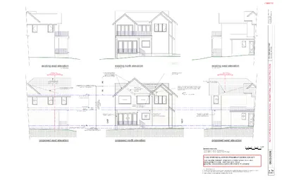
T C E T I H C R A L E B E O G I I D E H 4 8 8 9 . 4 5 4 . 2 1 5 . h p l t e n . l a b o g c b s @ e b e o g d e h i i l existing east elevation for reference existing north elevation for reference existing west elevation for reference existing construction new construction extend existing roof plane to create new gable over addition line of re-framed, low-slope cricket roof beyond midpoint of highest gable roof plane [new roof over addition] exisitng window exisitng window exisitng window new window 8'-0" pl. ht. @ east wall of master bedroom second floor 10'-0" pl. ht. @ 1st floor t i h g e h g n d i " 0 - ' 7 2 l i u b floor trusses extend existing roof as shown to create new gable over addition see structural drawings reframed low slope roof 'cricket' new construction existing construction . q e . q e . j d a e g a r e v a e v o b a e d a r g exisitng pitch break to remain dashed line indicates existing roofline to be removed line of re-framed, low-slope cricket roof beyond modify new eave overhang at this location to minimiize conflict with window / window trim drainage managemant at this location TBD - review in field 9'-0" typ. pl. ht. @ 2nd floor new window new window exisitng bedroom window new window exisitng window dashed line indicates existing roof overhang to be removed steel columns to remain in place T S A E exisitng living room doors exisitng kitchen window second floor is cantilevered see structural drawings new second floor to be partially cantilevered see structural drawings T S E W exisitng window exisitng door [460.50] t. / slab [per permit set dated 12.20.2017] [458.75] average adjacent grade [per permit set dated 12.20.2017] proposed east elevation proposed north elevation proposed west elevation exterior elevations scale: 3/16" = 1'-0" on full size sheet scale: 3/32" = 1'-0" on reduced [11x17] sheet 0 2 4 6 8 10 FT THESE DRAWINGS ILLUSTRATE PRELIMINARY DESIGN CONCEPT THIS DESIGN CONCEPT DOES NOT COMPLY WITH C.O.A. LAND DEVELOPMENT CODE - CHAPTER 25-2 -779 (J) [gross floor area exceeds allowable entitlement for this property] T E E R T S K A O T S O P 4 1 7 n o i t i d d a / l e d o m e r I N O T C U R T S N O C R O , I G N T T M R E P I , L A V O R P P A Y R O T A L U G E R R O F T O N . 6 2 0 2 3 0 8 0 . ELEVATION NOTES: • existing elevation drawings and setback tent data were copied from approved permit set dated 12.20.2017 • VERIFY ALL EXISTING CONDITIONS - REVIEW DISCREPANCIES W/ OWNER & ARCHITECT • match existing exterior materials, detailing, finishes, etc. p. 3a elevations ITEM07/17 remove door unit entire wall at this location to be removed, review temporary structural support solutions with structural engineer duct chase BEDROOM vaulted ceiling see structural drawings for extent of demo at ceiling and roof FAMILY ROOM 90 ceiling BALCONY area to be enclosed to create enlarged bedrooms demo and re-frame per structural drawings remove door unit entire wall at this location to be removed, review temporary structural support solutions with structural engineer duct chase new construction existing construction 2'-91 4" ✱ y f i r e v - r d h 0 7 / 0 6 x 0 3 t n e m e s a c . r p o egress window 80 x 50 / 76 hdr fixed ✱ match window height and header at existing windows in bedrrom BEDROOM new vaulted ceiling framing at this room, see structural drawings match flooring - feather in to blend new wall to align with existing see structural drawings duct chase 80 x 50 / 76 hdr fixed tempered / safety glazing NEW BEDROOM match flat ceiling in existing room match flooring - feather in to blend egress window " 2 1 0 1 - ' 6 ± " 8 - ' 3 4'-0" 8 6 x 6 1 ] 2 [ NEW CLOSET fittings per owner 28 x 68 1'-4" D P 8 6 x 4 2 pull down stair to remain in place NEW 1/2 BATH enclose nook in upstairs hallway see plan,detail this page duct chase BEDROOM vaulted ceiling r d h 6 7 / 0 6 x 0 3 t n e m e s a c . r p o i g n z a g y t l e f a s / d e r e p m e t BEDROOM vaulted ceiling 15" min. t e l i o t . l . c modify framing at this wall to accommodate in-wall tank T C E T I H C R A L E B E O G I I D E H 4 8 8 9 . 4 5 4 . 2 1 5 . h p l t e n . l a b o g c b s @ e b e o g d e h i i l 21" min. clearance @ toilet c.l. sink 15" min. 21" min. clearance @ sink plan detail - new 1/2 bath scale: 1/2" = 1'-0" on full size sheet scale: 1/4" = 1'-0" on reduced [11x17] sheet provide or exceed clearances at fixtures as shown dimensions shown are to face of finishes [ref. 2024 IRC R327 & P2705} FINAL FIXTURE SELECTION & SPECIFICATION BY OWNER fixtures shown in drawings are for illustration only select fixtures with care in order to insure required clearances fixtures to be installed per manufacturer's instructions toilet: DURAVIT Starck 3 compact wall-mounted toilet #222709 shown in drawing tank is concealed in wall sink: DURAVIT Starck 3 wall-mounted sink #07515 shown in drawing provide a local exhaust system complying with 2024 IRC M1505 exhaust air from this bathroom shall be exhausted directly to the outdoors [ref. 2024 IRC R325.2} partial existing 2nd floor demo plan partial 2nd floor proposed plan second floor plan scale on full size sheet: 1/4" = 1'-0" scale on reduced sheet: 1/8" = 1'-0 0 2 4 6 8 10 FT THESE DRAWINGS ILLUSTRATE PRELIMINARY DESIGN CONCEPT THIS DESIGN CONCEPT DOES NOT COMPLY WITH C.O.A. LAND DEVELOPMENT CODE - CHAPTER 25-2 -779 (J) [gross floor area exceeds allowable entitlement for this property] PLAN NOTES: existing plan drawings were copied from approved permit set dated 12.20.2017 VERIFY ALL EXISTING CONDITIONS - REVIEW DISCREPANCIES W/ OWNER & ARCHITECT dimensions are generally given to framing PLATE HEIGHTS VARY AT SECOND FLOOR match existing plate heights - verify in field WINDOWS AND DOORS: verify final frame & rough opening sizes with window / door supplier header heights vary - see plans, sections and elevations provide opening control devices at operable windows [ASTM F2090] at locations where bottom of clear opening is less than 24" above finished floor and greater than 72" above exterior surface or grade ELECTRICAL & LIGHTING not shown on plan, walk-thorough with Owner at electrical rough to locate fixtures and controls provide outlets / GFCI devices to code and per Owner's direction fixtures installed in closets shall comply with 2024 IRC E4003.12 provide wet / damp area rated fixtures where required SMOKE AND CARBON MONOXIDE ALARMS: provide if not existing: smoke alarms [hard wired, interconnected with battery backup] at each sleeping room and immediate common area outside of sleeping rooms [but not less than 3 feet from a door to a bathroom with tub or shower, except when this requirement will prevent the installation of a smoke alarm in a required location, and on each additional story including basements and habitable attics. [ref. 2024 IRC R310] provide if not existing: carbon monoxide alarms [hard wired with battery backup] outside each separate sleeping area in the immediate vicinity of the bedrooms. [ref. 2024 IRC R311] T E E R T S K A O T S O P 4 1 7 n o i t i d d a / l e d o m e r I N O T C U R T S N O C R O , I G N T T M R E P I , L A V O R P P A Y R O T A L U G E R R O F T O N . 6 2 0 2 3 0 8 0 . p. 2b second floor plan ITEM07/18 ITEM07/19 ITEM07/20 FEMA Floodplains 0 150 300 ft Thursday, July 16, 2026 Legend FloodPro Contour Minor Intermediate Major Parcel FEMA Floodplain 100 Year (Detailed-AE) 100 Year (Shallow-AO) 100 Year (Shallow-AO) 100 Year (Shallow-AO) 100 Year (Shallow-AO) 100 Year (Approx-A) 500 Year 500 Year X Protected by Levee The City of Austin Watershed Protection Department produced this product for informationalpurposes.It is not intended for or suitable for legal, engineering, or surveying purposes. It does not represent an on-the- ground survey and represents only the approximate relative locations of property boundaries. No warranty is made by the City of Austin regarding specific accuracy or completeness. Final determination of the floodplain status for a property must be based on a topographic survey by a Texas registered professional. For regulatory purposes, 100-Year floodplain elevations must be determined from an engineering model created in accordance with the Drainage Criteria Manual and approved by the City of Austin. ITEM07/21 City of Austin Regulatory Floodplains 0 150 300 ft Thursday, July 16, 2026 Legend FloodPro Contour Parcel Minor Intermediate Major Fully Developed Floodplain COA Fully Developed 25- Year COA Master Plan 25-Year COA 25-year (FEMA 100- Year Detailed-AE) COA 25-year (FEMA 100- Year Approx-A) COA 25-year (FEMA 100- Year Shallow-AO,AH) COA 25-year (FEMA 100- Year Shallow-AO,AH) COA 25-year (FEMA 100- Year Shallow-AO,AH) COA 25-year (FEMA 100- Year Shallow-AO,AH) COA 25-year (FEMA 100- Year Shallow-AO,AH) COA 25-year (FEMA 100- Year Shallow-AO,AH) COA Fully Developed 100- The City of Austin Watershed Protection Department produced this product for Year informationalpurposes.It is not intended for or suitable for legal, engineering, or surveying COA Fully Developed 100- purposes. It does not represent an on-the-ground Year (Shallow) survey and represents only the approximate relative locations of property boundaries. No warranty is made by the City of Austin regarding specific accuracy or completeness. Final determination of the floodplain status for a property must be based on a topographic survey by a Texas registered professional. For regulatory purposes, 100-Year floodplain elevations must be determined from an engineering model created in accordance with the Drainage Criteria Manual and approved by the City of Austin. ITEM07/22