ITEM05 C15-2024-0025 ADV PACKET APPEAL1 PART2 — original pdf
Backup
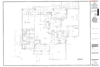
I I I -+i-1-11{,-'41', '~---+-----+--"/_1,p '· le" i~ ~---- ---,---.-- ---~rl ---- i I i 1 __________ L ______ _ ,- \ i:--c---.. \1/ '' I I I " ' " II 11 ' I MASTER BEDROOM ., ; J I ': I 1 I I ( -•~- J C- , ,----" I f ;' I - - - - - - - - - - - - - - - - - - - - - - - - - - - - - - - - , I IV") r \ / ✓ I I , , I ' KITCHEN I I "·" I I '"'',, 41-01' ~ , , , - - - - - - - - ' - · - - - - - -~ _,_ .. 0 -, ~ - - - - - - - - , Ir, ! , t i I "-_ -"',u~u~u---.---r-u--.'--4-r , , ~~ ---,l-----c,"-1~-~;-;-----Jjl-- BREJKFAST I AREA 1 LIVING ROOM 1 , ' :H I i I I I ' ' II ------ --1 I " i- i - FAMILY ROOM - --+---+- 1 I STUDY , ' 1 -STAIR UP J ,, wooD -- ·, ./Vll;:JJ ~ ' f ?~ >( ' UTILITY' P.R. 0 oo \ - - - - - t:t'.:::::==-:::::==,-t::...=•--=r'· -~-""--=---i;====r-i====:;1•r--___J_ 1, .I , i,;:- I /1 n GARAGE i ,---- ---,-- / . , FLOOR PLAN ____________ _ MAY RESIDENCE 6708 Bridge Hill Cove Austin, Texas TilE OFFICE OF EDWARD B. FRIERSON AJA ARCHITECT 4307 FARJIILLS DR. AUSTIN, 'IX 78731 Ali R1GtfB Rf:SllRv,;o FM AActil'l'l'?CT DRAWWGS AH) SP£C1F!CA11()1"S J.S INS'iRLJ!RcNTS Of sat\llCE SHAJ...L f\EMAJN Tl-IE 'lJ-IEY SHAU NOT 81: use:, CN PROPERTY OF TI-£ MCHITT'CT OTHER PROJEClS ~ ElCJEMI~ OF 'TJ;!S PROJECT EXCEPT BY AGR£EMEfiT IN 'M<ITING AND 'J\1111, APPROPAIJPRIAT'f: COMPeti- SATION TO TI-£ NtCHITECT CONl'RACTOR lS kl':SPONSIBLE FOO CONFIRMING AND CQJ!P:tiU,TING O!r.lOlSICf,IS AT THE JOB SftE. Tl-IE ARClilTE,;;T WU. WOT BE RESf'Ol'ISl&l.f FOR CONS'fJIUCTION MEAHS, MaHOOO TECHNIQUE$ 00 FOR SAFETV PRECAI/TIOHS AHO~ IH COtlN£CTIQN Willi THE PROJECT ................................... , .. , ........... ,,,,,, .. ,., TITLE: FLOOR PLAN SHEET: A 1.1 · SCALE: ITEM05/45-APPEAL1 c= I t- _j I I L L I ....I I L t I L ...! I I L ...L .. , - - -1 r I ., I I ' ' I I ; ; .. - - - - - - - - - - t- ---:-,_.... - ' - - , - - I I I ,,,.~ /\ \ I\ - . . . I I I I I I I -I I I I - -- . ! ' I I I I I I I I l 1-- -j CJ I ' ., . 1-. ' ----- ----- vP □ T I I f ;· I I f '-.. . I I J.. I ~I ,., --C - - - J \ . .. " u G I- ·I I- I r - r"' I \ :======tl7 _, 17 L .J I I I 1 - - _ _/j__"t- 1.-- - - - - - - - - --, rr I I J I I I - - - 'i !\ ., / • I --.. 'T I I - : \ I KEY:' EXISJING WALL'TO REMAIN _ EXISTING WALL, DOOR, WINDOW OR CABINET TO BE REMOVED ..,_ ___________________ ___, _DEMO PLAN- MAY. RESIDENCE 6708 Bridge Hill Cove Austin, Texas TIIE OFF1CE OF EDWARD B. FRIERSON AIA ARCHITECT 4307 FARHilLS DR. AUSTIN, TX 78731 DRJMilNGS l'IIGl'tTS RleSFRVFO BY ARCHITECT Al.l ,q,o:, SPl!CIFICA110NS /IS INSffl.UMENTS Cf SERVICE" SHAU. REMAm TitE 'fHEY SH11U. NOT SE tJSEO ct. K!OPERTY Of ilE AACHIT'!'CT OTHER PROJECTS OR EXTBISIONS OF 1lilS PROJECT EXce>T ev AGR£EMa(T o; 'M«l1NG ANO WTii A.PPROPROPR!ATE COMi'laN, SMlON TO TJiE AAC,!ITicCT CONmACTOR IS RESPONSllll..E FOR CONAAMINO A.ND CORRELATING OIMENSIONS AT nil: JOB SITT: 'fl-IE AACHITEC'T WILL NOT BE 1'!ESPONSIBt.E FOR CONSTRIJCTION MEANS 1/!En;o():S, TECHNIQUES OR FOR SM'.l:TY PRECMJTIONS AND l'RIJGRM,!Sffl CQN,IECTION 'MT!, TI-IE PROJECT l't.:'!-1.~ ... '.ft ...................... , ..... ........ . ....... ., .... ''''.' ' ... "' '" ...... ' , .. " ....... ,., ', ... ' ... '' TITLE: DEMOPLAN SHEET: A 1 2 • SCALE: ITEM05/46-APPEAL1 - ' I I ' ' ' $"/ ' - --- ' - --- • EXISTING CEILINGS TO REMAIN t ' ' :\ $'1 r • 1 - - - - - - - - - - - - - - - ~-----~4----------~:--,-+---1 ---+-,--+---l 1 - - - - - - - - - - - - - - - - ---- - -:~-----+-----I-I ~ ~ I ' 0 ,\ ' ' I I 0 \ (10!<) ' I I \ ' ' - ' \ ' ' I j \ 0---- T I I \ 0 ' i f_ I < __J_ □ C EXISTING CEILINGS TO REMAI~ - _, ' : ' ' - 0 0 r , I r ; j - - - - - - - - ,/_-;~ - - - - - - :=-~ -~ ~~-~~- ~--~ i -~ f----- ' - ~ -- ;~----- -·-- -------- □ -. -------- --- - -- - - - - - - \ I - .. . ' - . ' 9 ·--·· - - - ---- ➔ - - - • f ~ ~ r - EXISTING CEILINGS I ! ~~----MAIN LEVEL RCP MAY RESIDENCE 6708 Bridge Hill Cove Austin, Texas THE OFFICE OF EDWARD B. FRIERSON AJA ARCHITECT 4307 FARHILLS DR AUSITN, TX78731 512 • 502 • 9340 fU,SER',f'J) !IV Al'i:CHITI;CT DRAWINGS N-llJ ALL RIGHTS SF'ECJAC,1,.TIOOS AS INSTIUJMafr$ CiF smVICE' SH/\1..1. REM,fl,JN 11'E PROPSRTY OF THE ARCHITECT 1l£Y SHAU. NOT tl'I!: USED at OTHER FRQJECTS OR E.XTENSIONS Of TI·IIS PROJECT EXCtf>T BY AGREEMOIT IN v.RITING AND wrn APPROPROPRIATE C0MP£M S,,.TION TO n£ AACHITECT OONTRACTOR IS RESf'ONSIBJ.£ F~ CONFIMIING ANO CORRELA11MG DIMe.'SIONS AT THE JOB SffE 11-!E 11.FiekTI:CT wtJ. NOT SE RESl'OHSIBLE FOR CONSTRUCTICN,. MEANS, METiiOOS. lECHMOUES OR FOi, SAffTY ~ECMJTIONS ANCI :PROGRAMSlN CONNECTION \MT1'! TI-!E PROJECT .. , ............. ,.,,, ......... , '' ...... , .... ,' , .............. ' .... '" .... ,. .. ' "'' ....... ' .. ' '".' ....... ., ' ......... ' ... , '' TITLE: MAIN LEVEL RCP SHEET: A 1 3 • SCALE: ITEM05/47-APPEAL1 -----------=--=-=:--_---_-=_---=-=-=--==---=---=_ -~~~~;,;:=::_::::.::=~'---"r"-t-t ' i ~ - - 1 ) / I I -- - I J I I--? y ' I I / ',,..-" /!_....,, I I I ! ' i ! I -4W----Jf-~::::.L..J____J__-___J_-L-=k-~/ © I It_ --; :o SECTION -SOUTH ELEVATION ~~ ,, =-&As v,,,1ri,:£,15 (-r;?,) ,, - l - -' 0 ' :t: -,: -◊ -- ' - i ' ' i! MAY RESIDENCE 708 BRIDGE HILL COVE AUSTIN, TEXAS THE OFFICE OF EDWARD B. FRIERSON AJA ARCHITECT 4307 FAR!IlLLS DR. AUSTIN, TX 78731 512 • 502 • 9340 DAAv.vtGS NI) All RIGHTS ~O l!Y ARCHm;eT SPECIACATIONS AS lw.l'TRUMEWTS OF SERVICE SHALL Ra!A!N 'FH!l: '!1'11:Y SHALL N::rr BE USE!) Q<I Pl'<OF'!'RTV OF THI: ARCHt1'ECT OTHER PROJECTS Of! EXll':NSbS OF nus PROJECT EXCEPT BY AGREEMENT fH lll(Rl11NG ANO 'M7H Af'PllOMOPRIA7£ COf.lPEH. SATION lQ 11-!E ARCHITECT CONTR,1,CTOR ,s R£SPOWS18l.E FCR CONFIRMING AHO CORRELA.TING !llfl!l:nSIQtlS AT TIE JOO SIT.le Tl<E ARCHITECT WU. NOT !IE R.ESPON.S!Bt.e FM CONSTRUCTla-1 MEANS MfTI100S. TECHNIQUES OR FOR SAFETY ffi.£GAUlJON$ AtfO PROGRAMS IN CONNECTlON WTH THE PROJECT , .. '' .. ' , .. '' .. '.'"' .. '".'' ... ' '"'"" ... ' .. ''.' ' .. '' ' .... ' EXTERIOR ELEVATIONS A2.1 Tlll.E: SHEIT: SCALE: EAST ELEVATION ITEM05/48-APPEAL1 . . .• STEELDOOR/WINDOW TYPES L l , -------- I,, 1 ' t l .. I' -· - :1 :, ,' / ti=== .. ====;;;;:;;=====:;;::;:;;-t···------- ' r '~~------~'----~~,-= ~ - - - - - - -.... ·- -1 - . . - - - - - - - - - - - -~ - - - ' , ,. ' I / I I' I ' '="==-----•-··"c-'~-,,= \ / / 11 ' I j \ \ , , , / / I -·c=-t;;;::======ttFJ:;;;;;:::::;::::;::::::::;::::;::::::::;::::;:::::ifM:;;:::;::::;::::::::;::::;::::::::;::::;::::::=;;:r-:.. ···-·. -· I I I, I• i ii \ \ I ' n· ;;::;:__:::::;;::;:;:;;;;;:;:;;::_;;;;;;/~IF,;;;;;;;;;;;;;::;::;::;:;;;~.::::::: ... ~ rr...__ __ -...... ·71,;::;II ;;;;;::;::;;::;;;;;_=-=·=:;:::;;;:;;;::;:;:;;;;;;;;:7, r-17--~. - \ I '· ' ----- '--"------_,_+--'--------~-+ .... , ... , , · · - - - - - " - - - - - - -~e - - - - __ __,, _____ - -~ - - - - - -4 " - - - - - - -+ - - - - - - ' , -r,. f I 11,,'f ,;;, • •• • ·rtiov1!),t" ,";e,c,r: ,#',t,4'. :!,rt:.f't AHO ,t"l>K. J,looD C,UhO /'R<>it'OL ,,,,.a,ce ,r,iJ<:. .67:t!E'.<- /+->JO p~K.. /p,/0~,1 .. -:J ("6,...,l. ~ - _ =:~_.,PP,,y1,:u: /"/ii_.,, r"e :;;,-;~.-... -~------~--A-A ~ Fo% /ef"/:"Jt>I.) -::t Vi~ / / I ! I I I \ 11 11 \ \ I I / / I / . l=!R.rcl'- 51{.C. l··> =-===-=·=======·:1~/ f- t - - - - - ------- - - - -+ - -+ ~ - - - ' I I I z 1-101z 11 L 1 ' / I - • -~ . - - -~ ! ·~·---1'c-·-- .. ·-. I' ' / V ® WOOD CLAD WINDOWS ·MAY RESIDENCE 6708 Bridge Hill Cove Austin, Texas THE OFFICE OF EDWARD B. FRIERSON AfA ARCHITECT 4307 FARlllLLS DR. AUSTIN, TX78731 .. , ,;,.,;;r ·~11~/z.1 'Q;:~::'.;v-"~- . • Alt RIGHTS RE:E'M!D BY AACHrl'E'CT PAAv.1NOS Am SPECIFICATIONS n, JNSTRUUE,NTSOI' saMCE SW.U. REIMJN 11-tE PROPERTY OF TIE AAC-l-!ITECT "n,E'I' SHALL NOT SE lJSEO ON OTHER PROJECTS OR l;XTEt<SICMi OF ltlr-:l PROJECT EXCEPT Ii\' AGRtEMEJIT .. 1,mmHG AND wrn APAAOPRDtRIATE Cl'llifl'EN SATIOti TO ™E AACl-ll'!cCT CC>ITRA.CTOR IS RESPONSIBlE FOO CONF"'™'HG AND CORREI.AffiG DIIIIENSIONS ~T Tl-IE JOO SITE rnE ARCHl1'£CT M.L /,JCff SE RESPONSIBLE FOR CONSTmc:TION MEANS, UETI-tODS fECl-!NIOUES Ofl FC!f: SAfElY PRECAUTIOHS ANO PROGRAMS IN CONNECTION WTH THE PROJECT l'f. d1.:✓• ,.tl .. ...... , .... ... ., .... , , , .... , , .. , .. , .... '' .. " ... .,, ' ... '"" ... '' .. '" """.''' .... ' ... ' ...... " ................ , .. ,,. .. , ................................. . ,- TITLE: SCHEDULES SHEET: A3.1 SCALE: ITEM05/49-APPEAL1 double studs, face nail 10d @24"o.c NAILING SCHEDULE· joist to sill or girder, toe nail 1"x6" subfloor or less to each joist, face nail 2" subfloor to Joist or girder, blmd and face nail sole plate to joist or blocking, face nail top or sole plate to stud, end nail stud to sole plate, toe nail double top plates, face nail sole plate to joist or blocking at braced wall panels double top plates, minimum 48" offset of end joints, face nail m lapped area blocking between joists or rafters to top plate, toe nail rim joist to top plate, toe nail top plates, laps at corners and mtersect1ons, face nail bwlt-up header, two pieces with 112" spacer continued header, two pieces ceiling jrnsts to plate, toe nail continuous header to stud, toe nail ceiling Joist, laps over partilions, face na,I ceiling joist to parallel rafters, face nail rafter to plate, toe nail 1" brace to each stud and plate, face nail 1 "x6" sheathing to each beanng, face nail 1 "x8" sheathing to each bearing, face nail wider than 1 "x8" sheathing to each beanng, face nail 2" planks roof rafters to ridge, valley or hip rafters toe nail face nail collar ties to rafters, face nail 3-8d 2-8d 2-16d 2-16d 3-8d or 2-16d 16d @16"o.c 10d@24"oc 3-16d @16" 0 C 8-16d 3-8d 8d@6"o C 2-10d 16d@ 16"o.c each edge 16d@16"oc each edge 3-8d 4-8d 3-10d 3-10d 2-16d 2-Bd or 2 stpls 1 3/4 2-Bd or 2 stpls 1 3/4 3-8d or 3 stpls 1 3/4 3-8d or 4 stpls 1 3/4 2-16d@ ea bearing 4-16d 3-16d 3-8d bu,lt-up corner studs 10d @24"0 C built-up girders and beams, 2" lumber layers, at top and bottom and staggered. Two nails at ends and at each splice. 10d @ 32"o.c. 5116" to 112" wood structural panel 6d (wall) 8d (rooD 8d 10d 19/32" to 1" wood structural panel 1-118" to 1-1/4" wcod structural panel 6" edge 12" field 6" edge 12" field 6" edge 12" field 112" gypsum sheathing 4" edge8" field 1-1/2" galv. roofing nail or 1-112" screw, type w ors 1-314" galv roofing nail or 1-518" screw, type w ors 518" gypsum sheathing 4" edge8" field WOOD FRAMING. (continued) FLOOR TRUSSES: DRAINAGE WATERPROOFING AND VENTILATION DESIGN DATA Trusses to be designed by truss engineer employed by truss 1. manufacturer and in accordance wrth National Design Spec1ficat1on for Wood Construction, AF&PA, National Design Standard for Metal Plate Connected Wood Truss Construction, ANSI/TPI 1-1995 The following items are beyond the scope of the structural engineer and are therefore the responsibility of others. The client is responsible for arranging for the design of these systems Any mention of these ,terns on these drawings Is for information purposes only and does not relieve the client of these responsibilities. Drainage systems including surface drainage, any area inlets, grate drains, french drains and subgrade dram pipes Ground snow load: Wind speed (3 second gust): Exposure category Se1sm1c design category. GENERAL BUILDING CODE· The contract documents are based on the requirements of THE 2015 INTERNATIONAL RESIDENTIAL CODE. Local coce jurisdictions Design trusses for the minimum line and point loads shown on 2. plan (line loads from upper walls are minimum 100 lb/ft u n.o) and, unless noted otherwise on the plan, the following minimum area loads. Top chord live load: Top chord dead load Bottom chord dead load Max,murri deflections: under live load only· under live+ dead load. 40 psf 10 psf 5 psf U360 U240 Waterproofing systems including vapor barriers, roofing, flashing, waterproofing and drip edges. Live Loads. Ventilation systems including crawlspace and attic. STRUCTURAL STEEL STANDARD SPECIFICATIONS AND CODES· Structural steel design, fabrication and construction governed by ASD Specification for Structural Steel Buildings, Spec1ficat1on for Structural Joints using ASTM A325 or A490 bolts; and Code of Standard Practice for Steel Bu1ld1ngs and Bndges. 3. Pnor to fabncat,on, truss design drawings bearing the seal and regIstratIon number of Texas registered engineer shall be submitted to: MATERIAL· Builder/Architect for approval of all truss dimensions, pitches and elevations; All hot rolled structural steel plates, shapes and bars shall be 1. new steel conforming to ASTM A6-98A. Engineer for appoval of truss layout and design inputs. Unless noted otherwise on these drawings, structural steel Dead Loads. extenor balconies : deck fire escapes : passenger vehicle garages : attics without storage : attics with storage : rooms other : sleeping rooms : stairs : guardrails and handrails : roof slope 4.12 4·12to <12·12 12.12 and up 0- 200 20 psf 16 12 Roof Live Load: tnbutary area 5 psf 115mph C A 60 psf 40 40 50 10 20 40 30 40 200 lbs 201- 600 16 14 12 601- up 12 12 12 2. shall be as follows: W-shapes: C-shapes L-shapes HSS-shapes: ASTMA992 ASTM A36 ASTMA36 ASTM A500, Fy = 46 KSI roofing: tile (13 psij flooring ceramic tile 314' thick (10 psD hardwood 718' thick (4 psD carpet and pad (2 psD At roofs, unsupported plywood panel end and side edges shall 7. be backed with 2x4 flat blocking or Simpson panel sheathing clips #2 Douglas Fir-South Ceiling Joists: 4 Strongbacks: Install continuous 2x6 (mm.) strongbacks through floor trusses at mid-span and spaced a maximum of 10'-0" o.c Fasten with three 16d nails at each vertical. Where vertical web members are not suilably located for strongback attachment, install vertical 2x4 block fastened with two 16d nails at top and bottom chords. Restrain strongback at each end. All connection material 1nclud1ng beanng plates, gusset plates, 3. stiffener plates, angles, etc : ASTM A36 (unless higher grade is required by strength) Note: Materials indicated above were assumed in design. Prior to construction, builder must compare to actual matenals and weights and contact engineer if differences are found Actual dead loads must not exceed the loads md1cated. ENGINEERING Austin, Texas I (512) 402-0074 Locate strongback as close to bottom chord as possible. Deflections: CONNECTIONS. 1. See typical details on drawings. Maximum Rafter Span Tables for rafters with Heavy Roof Covering and J:!Ei Supporting Ceiling: Compare with rafter sizes shown on plan and contact engineer 1f discrepancies are found. 5. Alterations to trusses: Cutting and altering trusses Is not permitted. STRUCTURAL BOLTS AND THREADED FASTENERS· The building movement specified below is ant1c1pated and should be considered by the contractor in the performance of the work. 6. Bracing· Restrain top chord with floor sheathing and bottom chord with ceiling gypsum. Restrain trusses at points of beanng to prevent toppling. Unless noted otherwise, all bolts in structural connections shall 1. conform to ASTM A325 type 1. rafters ; floors/ceilings : others • L/180 L/360 L/240 GENERAL Dimensions refer to rough surfaces. The contractor must 1. verify all dimensions prior to start of construction the engineer shall be notified of any discrepancies or mconsIstencIes. All drawings are considered part of the contract documents. 2 The contractor shall be responsible for review and coordination of all drawings and specifications prior to the start of construction. Any discrepancies that occur shall be brought to the attention of the engineer pnor to the start of construction so that clanf1cation can be issued. Any work in conflict with the contract documents or any code requirements shall be corrected by the contractor at his own expense and at no expense to the owner or structural engineer. 3. These drawings are based on archilectural drawings by. Edward Fnerson received November 25, 2020 All work shall conform to the minimum standards of the bu1ldmg 4. code as well as any other regulating authonty over any portion of the work including those additional codes and standards listed m the structural notes and specifications 5. The engineer shall not control and shall not be responsible for construction means, methods, techniques, sequences or procedures, for safety precautions and programs ,n connection with the work; for acts or omIssIons of the contractor, subcontractor or for any persons performing the work; or for the failure of any of them to carry out the work in accordance with the contract documents, Site observations by field representatives of the engineer are 6 solely for the purpose of determining If the work of the contractor Is proceeding in accordance with the structural contract drawings. This limited site observation should not be construed as exhaustive or continuous to check the quality or quantity of the work, but rather an effort to guard the owner against defects or deficiencies in the work of the contractor. 7 All structures require periodic maintenance to extend life span and to insure structural integrity from exposure to the environment. A planned program of maintenance shall be established by the building owner. This program shall include ,terns such as painting elf structural steel, protective coating for concrete, sealants, caulked joints, expansion Joints, control joints, spalls and cracks ,n concrete STRUCTURAL FASTENERS: NAILS. FINISHES. GLUE. All nails sinker nails per ASTM F1667-95, steel wire, !-head diamond point, round smooth shank, bnght Where a preservative other than borate Is used and connectors and fasteners (including nails and bolts) contact treated lumber, use stainless steel connectors and fasteners, unless builder and supplier can demonstrate that pressure treatment is not corrosive to galvanized metal. WOOD FRAMING: GENERAL: ROOF AND CEILING STRUCTURE NOTES: Lumber. All matenals and workmanship shall conform with the 1. requirements of the latest "National Design Specifications for Stress-Grade Lumber and its Fastenings" by National Forest Products Assoc1at1on Where shown on plan, provide purlin same size as rafters and 1. braced with (2)2x4 braces at 48" o.c .. Slope braces between 45 degrees and vertical and lap onto rafters and nail All lumber shall be Southern Pine (S4S) conforming to the 2. standard grading and dressing rules of the Southern Pine Inspection Bureau. Unless indicated otherwise, the minimum grade of structural 3. members shall be as follows: studs. other lumber: no. 3 no. 2 M1crolam (LVL) laminated veneer lumber. LVL shall be 4. manufactured by Trus Joist, and design shall be in accordance with ICBO ES ER-4979. Ridge board braced as shown on plan with (2) 2x4 braces 2. sloped between 60 degrees and vertical Brace roof only as shown on plan Contractor must compare 3 resulting rafter spans to allowable span chart and contact engineer for approval of any necessary add1t1onal braces Unless noted otherwise, for ndges, hips and valleys, use one 4 mill size larger than the common rafters it supports Center any splices on an approved brace point. At point-of-support for braces, adequately block walls and 5. beams to prevent rotation and horizontal movement. Plywood or OSB Sheath1ng/s1ngle floor shall be exterior grade 6. 5. bear the following APA span rating· 15/32" roof sheathing: 1118" single floor t&g 15/32' wall sheathing: 32116 48oc 32/16 Maximum Ceiling Joist Span Tables Compare with ceiling joist sizes shown on plan and contact engineer if discrepancies are found. #2 Southern Pine Ceiling Joists: All floor sheathing shall be glued to the Jrnsts. The field-glued 6. system shall comply with the recommendations of the American Plywood Association. 8. All framing connectors shall be Simpson Strong-Tie. Where connectors and fasteners contact treated lumber, use stainless steel connectors and fasteners, unless builder and supplier can demonstrate that pressure treatment Is not corrosive to galvanized metal. STUD WALL NOTES. See architectural drawings for exact plate height Compare architect's plate heights and wall sizes to the table 2. below for acceptable maximum. Contact engineer if discrepancies are found. 7. supporting roof only 2x4@ 24" o,c. 2x4@ 16" o.c. 2x6@ 24' O,C. 2x6@ 16" o.c 10'-0" 12'-0" 16'-0" 18'-0" supporting one floor and a roof 2x4@ 24' o c. not permitted 10'-0" 2x4@ 16" 0 C. 14'-0" 2x6@ 24" o.c. 18'-0" 2x6@ 16" o.c spacing: 2x6 2x8 2x10 2x12 spacing: 2x6 2x8 2x10 2x12 24"o.c.16" oc.12" oc 9'-10" 12'-0" 13'-11' 12'-6" 15"-3" 17'-7" 14'-9" 18'-1" 20'-11" 17'-5" 21'-8" 24'-0" 24" o c.16" o c.12" o.c. 10'-4" 12'-8" 14'-1" 13'-1" 16'-0" 18'-6" 16'-0" 19'-7" 22'-7" 18'-6" 22'-8" 24'-0" from International Residential Code Table R802 4(2) with 20 psi live load, 10 psf dead load, L/240 allowable deflection #2 Southern Pine Rafters: spacing: 2x6 2x8 2x10 2x12 spacing: 2x6 2x8 2x10 2x12 24" o.c.16" o c.12" o.c 9'-6" 11'-8" 13'-6" 12'-1" 14'-9" 17'-1" 14'-4" 17'-6" 20'-3" 16'-10" 20'-8" 23'-10" 24" o.c.16" o.c 12" o c 10'-0" 12'-3" 14'-2" 12'-8" 15'-6" 17'-11" 15'-6" 18'-11" 21'-11" 17'-11" 22'-0" 24'-0" #2 Douglas Fir-South Rafters: from International Residential Code Table R802.5.1(1) with 20 psf live load, 20 psf dead load, U180 allowable STRUCTURAL OBSERVATION: 1. The structural engineer of record, or his designate, shall provide structural observation of the structural system for general conformance to the approved plans and specifications at significant construction stages and at completion of the structural system as noted elsewhere in the contract documents. The contractor shall notify the engineer a minimum of 72 hours 2. prior to the date the observation Is required 3 The following items require structural observation· Foundation reinforcing and pre-pour setup Framing pnor to insulation POWDER-ACTUATED FASTENERS (PAFS): WALL BRACING NOTES: Glue shall meet the requirements of the American Plywood Assoc1atIon adhesive specification AFG-01 and shall be applied as directed by the glue manufacturer. Glue may be applied manually or with pneumatic or electric equipment. EXPANSION ANCHORS. Simpson Strong-Bolt, 112" dia., installed as directed by manufacturer. 6. WOOD SCREWS, LAG SCREWS AND BOLTS· Wood screws shall comply with ASME 818 6.1. Unless noted otherwise, screws are #8. Lag screws shall comply with ASME 818.2.1 Unless noted otherwise, lag screws are 1/2'' d1a. by length as required to penetrate secondary member entirely minus 112". Applicable ASTM specifications for bolts. For common bolts: Fornuts For washers: For threaded rod: ASTM A307, Gr.A (Fu= 60 ks1) ASTM A563 ASTM F436 ASTM A36 (Fy=36 ksi, Fu= 58-80 ks1) PAFs shall comply with CASO NER-272. where permitted by details, wood sill plates may be fastened to the concrete slab using powder driven pins following manufacturers recommendations. The fastening system shall have ICBO approval Pins shall have a minimum shank diameter of O 177", a minimum length of 3 114", and be spaced per the details FINISHING MATERIALS: 1. Masonry Veneer. Maximum wall height: Install over a backing of wood wall and a limited ,n height to a maximum of 30 feet above the foundation (38 feet permitted at the top of gable ends). Masonry on wood: Where indicated on plans, masonry b weighing less than 40 psf may be supported on wood framing (deflection l1m1ted to U600). Install a movement joint between the veneer supported by wood and the veneer supported by foundation. Anchorage: Anchor to wood wall framing with c. corrosion-resistant 22 gage x 7/8" corrugated sheet metal ties spaced a maximum of 24" horizontally and 19 5' vertically. Lintels over openings. Support masonry on loose lintels per d. code supported on masonry to foundation at each end. Isolation Joints: Install vertical isolation/expansion joints at e. approximately 25 feet on center 3 Bottom plate. Treated 2x same width as wall studs Anchor with 1/2" d1a. anchor bolt embedded 7" and spaced maximum 6'-0" o.c. Locate anchors within 12" of each end of each plate section. Attach interior walls to slab with pafs spaced at 12" o c with 4 two pins 6" and 10" from each end of each plate. 5. Where joists, trusses or rafters are spaced more than 16' o c. and bearing studs below are spaced at 24" members must bear within 5" of studs beneath. a. Drilling and notching - Studs: In exterior walls or bearing part1t1ons, notch a maximum of 25%. In nonbeanng partItIons, notch a maximum of 40%. b. c. Any stud, bore/drill no closer than 5/8' to edge of stud and not in the same section as a cut or notch and a maximum diameter of 40%. d. Studs may be bored to 60% of stud width provided the stud Is doubled and no more than two successive studs are bored. With engineer's pnor approval sImpson HSS/SS stud shoes may be used in spec1f1c cases of notches or bores exceeding these maximums. 7. Dnllmg and notching - Top plate· When piping in a wall necessitates the cutting of a top plate by more than 50% its width, use a Simpson RPS strap lie at each plate with six 16d nails each side of notch. 1. Braced wall Imes Using braced wall panel construction in accordance with the prescriptive methods of IRC, brace walls as follows b a. Exterior walls. Continuous structural panel sheathing (thickness as noted above), including above and below openings, shall be used on the outside face of all extenor walls (blocking of edges not required), and any braced wall Imes that include an exterior wall are considered adequately braced. Interior walls: 1x4 let-in braces sloped between 45 and 60 degrees from horizontal and notched into top and bottom plates and intervening studs and attached with two 8d nails at each plate/stud or sImpson WB wall bracing installed ,n accordance with manuf. specs. or 1/2" thickness gypsum board minimum 48" wide attached to studs w/ 6d nails@ 7" o.c .. Bracing locations: As described below where 2 architectural layout will not permit the application of these presc1ptive methods, use engineered shear walls as indicated and detailed on these drawings. Contractor must review drawings prior to construction and contact engineer if discrepancies are found. a For one story or top story of two or three Locate at each end and at least every 25 feet on center but not less than 16% of braced wall line b First story of two story second story of three story. Locate at each end and at least every 25 leet on center but not less than 25% of braced wall line. Locate braced wall panels within 12'-6" of the end of each 3. braced wall line Out-of-plane offsets up to 4'-0" are permitted ,n braced wall Gypsum Comply with GA-216-2000 "Application and Finishing 2. of Gypsum Board." Flex1b11ity details in GA-216-2000 such as control 1rnnts and comer details shall be used. 4 lines. Tile: Comply with American National Standard Specifications 3. for the Installation of Ceramic Tile. Flexibility details in specification such as control and expansion joints shall be used. Alternate braced wall panel 5. panel constructed in accordance with IRC R602.10.6 can be considered a braced panel. In one and two story houses, a Unless noted otherwise, install Simpson H2.5 hurricane ties at Block beams, Joists, rafters and trusses at beanng as requ,red 8. every rafter 9. to prevent rotation. HANGER SCHEDULE Member Size Simpson Designation Floor Load Roof Load 2x4 2x6 2x8 2x10 2x12 (2)2x4 (2)2x6 (2)2x8 (2)2x10 (2)2x12 (3)2x6 (3)2x8 (3)2x10 (3)2x12 LU24 LU26 LU28 LU28 LU210 LUS24-2 LUS26-2 LUS28-2 LUS210-2 LUS210-2 LUS26-3 LUS28-3 LUS210-3 LUS210-3 445 665 890 890 555 830 1,110 1,110 1,110 1,390 765 960 1,000 1,250 1,265 1,585 1,765 2,210 1,765 2,210 1,000 1,250 1,265 1,585 1,765 2,210 1,765 2,210 (2)1 75x11 875 HGUS48 6,805 7,925 (2)1 75x14 HGUS410 8,780 8,940 (2)1 75x16 HGUS410 8,780 8,940 (2)1 75x18 HGUS414 10,015 10,015 (3)1 75x11 875 HGUS5 50112 9,155 9,155 (3)1 75x14 HGUS5 50114 10,015 10,015 (3)1 75x16 HGUS5 50114 10,015 10,015 (3)1 75x18 HGUS550l14 10,015 10,015 6. Truss bracing: 7. Load transfer through inter-floor space· Use same-size blocking to transfer load from upper walls/columns to lower supporting walls/columns/beams. do not place point loads on unsupported floor sheathing. 2. 3. Threaded rod: F 1554 grade 36 Pms: ASTM A36 8. Transitory floor vibration and sound transm1ss1on- The floor system includes no measures to specifically control flcor v1brat1on or sound transmission. Expect similar pertormance to s1m1lar systems In similar projects. Contact engineer prior to construction if specific performance criteria are desired. ROOF TRUSSES: Trusses to be designed by truss engineer employed by truss 1. manufacturer and in accordance with WELDING 1. Standard D1 .1. 2. to E70XX (SMAW) ANCHOR RODS National Design Specification for Wood Construction, AF&PA, National Design Standard for Metal Plate Connected Wood Truss Construction, ANSI/TPI 1-1995 GROUT 1. of 6000 psi. Welding shall conform to the American Welding Society Unless noted otherwise, electrodes for welding shall conform 1. Anchorrods: ASTM F1554 grade 36 Grout: non-metallic, non-shnnk grout with a mmImum strength Local code jurisdictions HEADED CONCRETE ANCHORS. Design roof trusses for the minimum line and point loads 2 shown on plan and, the following minimum area loads, unless noted otherwise on the plan, : Headed concrete anchors shall be nelson headed concrete 1. anchors (or approved equal), and shall conform to ASTM A108, grades C-1010through C-1020. Top chord live load. Top chord dead load Bot. chord live load. Bot. chord dead load: Maximum deflections: under live load only: under live+dead load: 20 psf 10 psf Light roof 20 psf Heavy roof 10 psf 5 psf U360 U240 Anchors shall be automatically end welded with suitable stud 2. welding equipment in the shop or in the field. welding shall be in accordance with the recommendabons of the nelson stud welding company VERIFICATION OF EXISTING CONDITIONS: Existing conditions of the existing structure are unknown, and 1. the contractor is advised to verify all pertinent dimensions and conditions pnor to construction 3. Pnor to fabrication, truss design drawings bearing the seal and registration number ofTexas registered engineer shall be submitted to. A pre-construction meeting between the contractor and 2. Engineer is required to determine appropriate intervals for s,te visits by the Engineer 3. In as much as the remodeling and/or rehabIhtatIon of an ex,st,ng structure requires that certain assumptions be made by Engineer regarding existing cond1t1ons, and because some of these assumptions may not be venf1able with the Client's expending substantial sums of money or destroying otherwise adequate or serviceable portions of the structure, the Client has agreed to bear all costs, losses and expenses, including the costs of Engineer's Add1t1onal Services, ansmg from the discovery of concealed or unknown conditions in the existing structure and foundation. Builder/architect for approval of all truss dimensions, pitches and elevations; Engineer for approval of truss layout and design inputs. 4. Strongbacks: mstall continuous 2x6 (mm.) strongbacks through trusses at mid-span and spaced a maximum of 10'-0' o c Fasten with three 16d nails at each vertical. Where vertical web members are not suitably located for strongback attachment, install vertical 2x4 block fastened with two 16d nails at bottom chords Restrain strong back at each end Locate strongback as close to bottom chord as possible 5 Alterations to trusses· cutting and altering trusses is not permitted. Restrain top chord with roof sheathing Brace bottom chord with 1x4 spaced per truss designers requirements (8'-0" maximum). Restrain trusses at points of beanng with blocking and hurncane ties per details. Brace web compression members with continuous 2x4 per truss designers requirements. Install 2x4 X-braces at third points of common truss span. Extend X-braces from girder truss to girder truss CLIENT Christy May ~ C: a., -0 en ~ >, ro ~ Cl) C ro ...J "' ro = X :c Cl) Cl) l ·- -~ "' o, - 1J !: Ill ::, CX) <( 0 ,-... (0 ISSUE package 1-FND for construct1on 1 a - rev1s1on for review 2 - rev1s1on for Permrt date 11 Jan 2021 19 mar 2021 19 mar 2021 SHEET TITLE Notes SHEET NUMBER S1 .0 ITEM05/50-APPEAL1 • -- --- --Exisbng concrete covered -- ' • - - - terrace I - - - ,--- - j I i I' \ \ 11' -3" _63~•-3~• - - - -+ - - - - - - - - - - - - - - - -~24 ' -11 " ---- - - - - - - - - - - - - - r - - , J __ ' I / I I I I I I / I -- I ! ' -7-~ Ex1stng -=.:._~\ \ \ ' \ I \\ \ \ \ '' / I I ,' I / /_ - - i / / i I I I I -- ' ___ _J I! i ! i ; I ' ' - I I I / I / ' I ......, 1a S30 - - - - - - - I • 1d S30 I I 2aS30 I I I 2aS30 I I i~ _ _ _ _ ~ J_ I _ _ _ __ ......, l ~ ~i ---,- -~·-c ,,._,,--.-" --r-:---,-->-i""' ----;,-v,,---;c ;,---;-7"""<1"< -;x;rx-,,,::s:r:/~< o ► Zl m 1 S30 ;:<.J>'· ', · . . ·(1 L~~, \," T~J,; 2a S3 0 • I I I I I I ~----~B'-7112~•------ 0 7':ZJ!2" - - - 12'-8" - - - - - - - - - - _22'-§"__ ----+- 22'-5" i ' "T - - - - - - - - - • I ....... 1eS3 0 Ex1st1ng Foundation Plan 1/4' = 1'-0" Full Size, 118' = 1'-0' Half Size PLAN NOTES See S1 0 for notes 2 3 Unless noted otherwise, slabs are 4" thick concrete slab-On-ground remforced w/ #4 @ 16" o c e w Pnor to any construction, Builder 1s responsible to venfy ex1St1ng cond1t1ons and verify all d1mens1ons with Architect ' , I I 0 I " il l I DUFFY! I g I t ll 0 • 1 Austin, Texas I (512) 402-0074 ENGINEERING PROJECT NUMBER 20198 CLIENT Christy May (].) (.) C (].) "O en (].) 0::: >,. ro ~ (I) C co --' Cl) "' :i: X (I) (I) t- - -~ Cl) C) - "Cl £ Ill :, <X) <( 0 I'-"' ISSUE package 1-FND for construction 1 a - revIsIon for review 2 • revision for Permit date 111an 2021 19 mar 2021 19 mar 2021 SHEET TITLE Foundation Plan SHEET NUMBER S2.0 ITEM05/51-APPEAL1 ' 1=3~--------------------------------i3' __ ~-,-------------------co•nb:-n•uo•u•s~(3:)~1~7=5~x1~6:------------------~~~-<~"-=-"t,,7,_-----_---;-----------------------:-,,j.:'E-~,-;;-~ ~',,t/,/ l I dropped beam max span@centerspan 25'-11/2' ,:) ,-,_, ' I_ __ I I ~1 g>,2:l I -m -g 1 e l ~, ~ §: I I I I I --1 I ' _________ existing rafters & celling to remain (2) 1 75x14 LVL hdr span 12'-6' (2) 1 75x14 LVL hdr span 13'-0" ~ - ex,st,ng --~ , ce1hng _,---- ex,stIng / / / ceiling , '~ ...... _____ ex1sbng rafters & ce1l1ng to remain (2) 2x8 hdr Span 4'-4" ------"fll' , - - - - - - -7 : I t ;'-- existing J ce1l1ng 1 ', ' I - (2) 2x8 hdr span 5'-0' (2) 2xt0 hdr span 6'-0" ~ - existing --'-- ceiling ~ (2) 2x8 hdr span 6'-0" (2) 2x8 hdr span 6'-0' .~ exIstmg _ / ,;-"/ ceiling 112· sheathing on - ~ diagonal 2x4 kickers ~ nailed to parapet studs at top and continuous 2x4 at bottom \ \ roof buildup per Architect', " I Ceiling 101st per plan _ } roof Joists on stud wall w/ Simpson H2.5 '' ! I ! I C roof buildup per Architect·,. I \ Ce1l1ng J0ISt per plan j , I ' '' 112" dIa tlireaded rod @32'oc, from top of parapet to stud wall top plate as shown .-,..- -Headers per plan Masonry veneer (< 40 psf req'd) Section! 1 3/4" a 1'-0' 1 I i 0 --- L •''""'" steel angle attached to header w/ 1/2" d1a lag bolt @30'oc m vertical slotted holes ENGINEERING Austin, Texas I (512) 402-0074 Stucco veneer per Architect n-,)i--- -- ---- - L 7x4x3/8 steel angle attached to header w/ 112" d1a lag bolt @30'oc m vertical slotted holes Section I 2 3/4" - 1'-0' PROJECT NUMBER 20198 CLIENT Christy May ~ C Q) -0 ·- Ql C j "' "' -= >< I Ql Ql I C) c -o - ·~ 00 ::, co 00 <I: 0 l'- (0 ISSUE package 1-FND for construction 1a - revIs10n for review 2 - revision forPerm1t date 11 Jan 2021 19 mar 2021 19 mar 2021 SHEET TtTLE Lower Level Framing Plan SHEET NUMBER S2.1 I I I i Beam per plan / I I, Steel column per plan __ ,// / 112" dIa A307 bolts _ ) I , / I ' / : 1 1 ' ' 1 /4 • thick steel plate _ _J. welded to form saddle I Steel column per plan - _ / ) I welded to base of saddle wl 3/16' flletall around Elevation View saddle connection Top View saddle connection Centerline of column - - - - - - -1 Base Plate elevation view Steel column per plan -- ~ -~ , 112' thick base plate \ \ ] 3116 '\ Opbonal .f-/-1/2" -\ • high-strength grout bed Anchor Rods -=-~::: ) (2) 5/8' d1a threaded rod embedded mm 7" and epoxy grouted Base Plate plan view Steel column per plan ___ -;:.-- @- t ___ 71/2"J • I I •----- 7 ~1 Steel column base plate I 3 1112' a 1'-0" ------ ' , 1 existing hdr -, I I rn I j "0 : ~ .c; I ' ex1st1ng hdr L _J ex1Stmg hdr Wood beam per plan --------- ---- ----- - - - - - - (2) 2x10 flush span 4'--0" i! ' , ex1st111g (2) 2x12 flush 1, " 1 11 ; : " ex1st1ng (3) 2x12 flu\h __ J __________ J ___ - -- :1 ___ '.:,_ _____________ --- L, - - ' (3) 175x18 LVL flush span 23'-0' 11 'I !~ Elevation ' ~ I El: 1i5 I ·, , 1 existing 2x8 101sts 1 @16'oc g,~ 1 ~ I (---,---..J_--,----"'-"'--'-'-----'-----'----➔ ,, I ;;j I I,, I I I I I I I I I, I I I 1 I ' ,I " ,, ,I II ,, I :; ,, II " 'I ,, " " ,, ,1 I ' ' ' Ii ,, ' I' I I II II I' II II I 1: I (2) 2x10 hdr span 6'--0" - - - - - - - - - - - ~--+1, " " I ,, ,, ,, I• I' I• I, ,, II ,, " " " " I " II II ,, 'I ,, ,' 'I I I I ', I 11 ' I ! ,I I II II II " ,, ' ii ,, i ,I " ,- V V V V V V V V I > > > > . . . - A A - - , hdra span 9'-10" hdra span 9'-10" Ceiling/Roof Framing Plan 1/4" = 1'-0' Full Size, 1/8" = 1'-0' HalfS1:z.e ~ plan north PLAN NOTES See S1 0 for notes 2 Pnor to any construction, builder to coordinate with Architect to verify existing conditions and feas1b1l1ty of the proposed framing ...... , 2S21 I I ' ' ' I ITEM05/52-APPEAL1 Detail notes Use caution to avoid exIstmg reinforcement particularly post-tension tendons and anchors, 1f present Existing grade beam / ' - (roughen face of concrete) 6'x6~ haunch - 6 mil poly shp sheet l (any required vapor barner to 1 be specIfIed by others}/ ' I Slab - thickness and reinforcement per plan 6"x6' haunch 6 mil poly slip sheet -1 (any required vapor barrier to / be specified by others)/ 1 $topofslab _________________ _ ____ per builder or architect ] ! Slab-----4! thickness and reinforcement per plan /1: Compacted select fill per notes- {depthasreq'd) ,.,...- Beam Remforcement ,,.,,/ per minimum requirements Optional constructIon Joint Fdl to final e $topofslab --_::_::_::_::_::~::-_::_::_::_::_::_:: __ :_:f:_::_::_::,::"';:,::_::_::_::_-::~;:0-::£::_::~:;ii;;:,;i.,.;::,.;:;,=tc:~~;: 0 =========,:,.. 1 _______ _ _________ ------ - <:________ - - - - - - -- - -~ - - - ___ _____ II 11 :.,_, .cc col: 11 11 :: Ii :: :: ii 11 :: :: II 11 :: _ -~ - ..... ~~•= .. =~"-= .. =,.~J_":--_.-_-_-_.,..-L--. - -~-=-\ i-_,:: __ --~-=---------=-- / - , \ -~ -- :. ~ ~ --,- --- L 11 11 / - - .7---=- -- -- i - - - ;,bearing strata ,_, vanes - - \ _ __.L-- -·-7"c.=-=--=-- j - c_ - - - - 1 per bwlder or arch1~ ~ , ~ 1=: E )~~-~ ~ :. /lhexJSting grade o m ~ ~ ! E! -g §: i <1:1 22 a:i _ g> c: ~~ ~ ;;; Jg ~ ,_,vanes v, (ti J Grade after removing extStmg soil __ / per notes and before placing compacted fill __ 7 - - .L....... / ____ / _L_ -7=·-~7-~r -~---- - - -,-,i:- ---::::·=-..cc. ' ,_ - - - - - - - - ---✓ - - - - - - - - - - - - - L - ( l:-~;1--~ :l. t:--,, t lil J: / :: <' :t., , {Q~_J..::_ ']~ :: : : ii 11 II ii :: :: II 11 II 11_..- /ii / :: r ■,II ' II 11, II I! II II 11 ccll ' I c) I :: :: " 1 " II II 7;-- --7r 7r-----7.-- 11 II II II II II II 11 II II 11 ;:: 1: , II II ~ / - - Wall Reinforcement #4@18'ocewbolhfaces Tie every other vertical bar to beam stirrup above Stop horizontal bars at bottom of beam stirrup Wall Drainage 1" dIa PVC weep pipes @6'-0' o c max and located wJ!h1n 4' above final grade Extend pipe mto bagged gravel back fill <e,k'.11 r-:::,~';:-,c;-,:-,,,,-._ $ existing grade vanes - - --1 II II j t - - - - - , - - - - [ - - _L_~-Z~ $ bearing strata vanes - - - - or minimum 6" into engineer approved grade BASIC BEAM deep beam requirements New grade beam @ existing 11 e Perimeter grade beam addition 11 d i as ! req'd ,.._......,._ .. Existing grade beam---.....___ (roughen face of concrete) ~ \\ #5 x18" dowels@ 12" 0 C and embedded min 6' into existing grade beam and epoxy grouted / 1 / / + ! • l,,,.,-- Riser height cp per Archdect __ _L - - \ '--- Perimeter grade beam s1mIlar to ta/S3 0 Steps to grade I 1 S New grade beam@ existing covered terrace I 1 f on bedrock or minimum 6" mto engineer approved grade -T ~::mBe:,mg T-:-:-~:W,dth I~-:~~e~orcement (2) #5 (2) #5 #3 @ 36" o c top bottom stirrups minimum 1'-0" ' BASIC BEAM minimum requirements 11 II II II :: : I "!''. fj ~ n I~ FIH-sIde face of wall or beam ,r-Add12"hooktoendof 11 II II II :: ) l I / ! :, :, I i 1 use corner ars same I i \ diameter as horizontal rebar :: :: L -+i-- - - each honzontal rebar OR b \,\ w/18"Iegs ' ' II 11 ~~~ - ; , ,_ ; ; ; : . t l t= .£ l .B§ \ : l : ' l ' . ,~ II II II 11,, II~ II I I I ' :, II II~ fll ~ , , 3 '& :NS ' . : :=~ z ; ; ,= - - - ' I '1 "'---- Locate first sbrrup close to intersection - ,~-:~ " " " " " " II II ( , \ -- Edge of concrete at comer II 11 II II II II I II 11 ~ , - - F1ll-s1de face of wall or beam II II II II I I: ffl ~ I : : : : : : • ... • __ , ,J_ L ~h::ntalreb~w/18'1egs /( Add 12• hook to end of each • 1 horizontal rebar OR use corner \ bars same diameter as 1 ~=~ i s : - -~~=2 : z t \ : : u " L 11 n 11 :• ' 4 :F \~ - : : ; , - - -~ .= ; , / / \. Locate first sbrrup close to intersection .J. __ Edge of concrete at corner T-intersect,on Exterior Corner Plan Views of T ical Corner Details Perimeter grade beam I 1 Unless othe!Wlse noted, all details are 3/4" = 1'-0" Full SIza, 3/8" = 1'-0' Half Size a Note Where fill depth exceeds 'l-0" (measured at mtenor beam mtersecbon}, install hard pomt 12• d1a concrete piers (formed or drilled) through the fill and remforced with (4) '#4 vertical ( extend 12" into beam) and #3 ties @ 18" o c Edge of excavation of exIstmg slab must be vertical and rough ~~-#3@12"ocew ( Existing slab-on-ground I I #~ New 3000 psi concrete - slab-on-ground on new 6 mil polyethylene sheet -------- Backfill with sand, wetted and tamped into place - - - - - -~ ==- ~~\f~;= - - - - - - ~ - - - - \ i - - · - - - - - - -- - - - - - Beam w,:~~- Beam Reinforcement mIrnrnum • _ __1',0" I __ • ' top bottom sbrrups (2) #5 (2) #5 #3 @ 36' o c Interior grade beamI2a Slab-on-ground repair! 2r ENGINEERING Austin, Texas I (512) 402-0074 PROJECT NUMBER 20198 ,r I • B g Christy May r CLIENT • I I 0 ~ i f I Q) u C: Q) "O ·- Cl) Q) 0:::: >,, ro ~ (!) C Ol ...J U) - Ol -- X ::c (!) (!) I- - -~ U) - c» 'C 5 ID :::, 00 <( 0 t-- co ISSUE package 1-FND for construction 1 a - revIsIon for review 2 - rev1sIon for Permit date 11 Jan 2021 19 mar 2021 19 mar 2021 SHEET TITLE Details SHEET NUMBER S3.0 ITEM05/53-APPEAL1 :~~-,1. ~--Nc:::C,.,v~ f.!~ •---s ,hi: (';-.,-,,.,-.,N Fe,~ ,'J,'<ftf! - i . G T "I' -- 0 \ jO L , _ \ \ - - . Sr. '::/1E:i""li CN'S Sl::_,1 0 0 .__ •it. , \!.-::1. p <) ~(>~ / ,--:., •t-B 11 6, 1'1<1'.' W } -~•1 V:..lE ( '5' D f &.1 1Fr-= ld~!~2-. <J ■ L owe. H oNu,.,.li!>tr F°JJu.io 0 • :'.'.AwC Il<W [{.; FtJ4'J O !"!o .., w. .. uh,r :;.. ,• STA TE O F 'l"EY.A.'.:L COUNT 'f O.F TR.A VIS: i t lt} ..J) I «) )J A) R ::t:. ,:b ~ '() ~ ~ ~ ~ i ), JJ,'tf)~3~;¥i[:i;I~;f;s{f ~ Pw -~~:~•~::;. '.I'::: K, '",,;-llf't- fJ. f.. L- 0 ,.;_.5, £.,,; 4U,1, FcP 14.mC'.' c>t-<; .,h,,<J fh' Gc ~6r.,i..,,J,_,.,..., .. ~-;;z.1e5.,,._, , ,4 (',4.(X.. t.»;,.;1~1 ;hm' CMhhUWn. F- ~ t.,,.>,4-4_.,/- A££ Stfr (Q<_7.</ ;,-; :~~L . _ f'A~6- .. 5 ,f !DG E ST,\TZ 0 1: 'f~"::XhS: COU:i\T'! OF TH. AV ;S : , .. ,,, $ "' i>il~i> _I J1;,;_ ,i;_ 1/!7 l~~iiI/~~i1.;i:~lf l1Ji!~~~iif :)j'.}l)f{f {{:{[. ::;J~~f {f ji}tt~:? •~:~t;}i_f"~J,J,\:[:~~~,;:l:,~':}t;::,:::?:s:s.•~~:iJ,,'£2:Z~•:~t1:~~~l;J'.:i~•;;~,'!~f-'f~~?i~?c ;~}::1,:;:~~f\'.,'~~::,f,•::/;;:~~~t}~:\ii~,~:~~: .:-I::~~•t~)~'.,:{{:}:;{ :.i~t,h" P!;t't.',;-.:;;,;~,ii'~;'-.;;:,:,:1 'J. 3.:':i o:1 e r ~·,,-; <..f ia,,::i t o hr: j,- , ,n '-'.Jl 0" , C,),.,r,ty, 1c·xns, docR !1e r e 1·,y suhn·, 1l t hir, plat aJ a isul).J1,: ! &io.i or .%1.i.<.? BRIDGE HJ .L L S 'JRlJJV.! Si ON, am! cioe o he r e Uy dcd.i c a t e ;o t h ,: p uiJ l i: d i~ . .; 1r ce ! :, a. nd c,J. :; en, 1;< r, \ ·, f:'itne~:-. 1 1 c se l of tic s a, d , o r o v 1 i.llo,, .,_ ,m. UJ. ~ ,a ,i J ,(' 11 :\ w i , r 1t 1s P, t'U d.P-n t n R. k th s 'h e ~ - '.'c s ,dv.Jw:1 h <"rf..1 - d.vv ol _/:}_f/1/L~ _, ~-w1 __ __ _ _ '<i<~-f2,,.,,;,.._,.. ____ _____ /\ t, :.. T S t•,~r ,:>[,~ rv , , 5.'\ 1 ' , Y, JJ _ /<1111-if' _ L)it; (.,__ _ __ __ __ _ C!-.<·r , P t e s ;der,L N a ncy e , oplT,l. nl Co1 JH,r,. ,vn Lv1,x l) 47 C! C ... e::,s t way Drive "f p, x.as STAT E OF TE XJ\S: COUN T Y UF T 1tAVlS : ti1e unc!er:.i1~ned J.Jthc-r: r y k t:o•.,i: ! ,: u112: 11;. J.ne th:.t h~ e , ., ~1,'.1.•1! t !:e l'l<ln,r. o ~ tru,,._ .-1::,,- le h,, the :::, e ,·;; ,)r,;;U ~- ~r-p e <l.rNi Narwr Becker. Pr e.'iiciYr.t, L'.1'~X \"l.' '1<,sc rFlr.-, e is subscrd>"!d to i h c fori\c:o >.nt, in:;tr u rr,ent o n r p uGC'S ;:,.nd c,on:::id t.i r.l.t;on~ liu:.r1~in e:cpr t-F.!' Pd . day oI ___ ~-- - _ _ , 1982., A.D. rITCr.e.rd R~· L1'"'·1"u7, - - -- -- 01 r e ~~to!" ·:if P'.a,rn~•~b'. ~ L'l11b ,F": 041A l!<Jl~ (D ~~°/3T,=• W.oo ' /3 -'8 o :,.,;:i, .1;, ' .:::f.!I,;;' ~-© <j.S'"oo t.c-. .:>' B, :'S ' !s ,·::; ' )$ . '7t' <;o.o" ,Z,..,.•• 4• /. 7i' Z.41 . ~f-' :':>."lt' {~~jjl $s•oo,' i81,Sv' f•,.1, ! ' 11/, !;, :1'/ i'i'' 2·~. , • I~- '1,'3' lt ,8,~' Zf-.31-' 14~. 1t> ' t, .t_ C/'i £<::,.$';- " fS . .!'<' l, ~::-,r;..k!ll l'!ei. l l:-';-;,nkEr., am .l.uthori,1t;?<! :.:.rickr ~he i.awa o!: the :', t alc c.f Tex;:ia, to pra..:ti.n: !he profrs::i i.o:~ •)f c;,._rve)" i. ng, <1!1.:i ne: r cOy ;; e r t :fy ~!; a \ th is i ;.! U• i~c c1, ;; d :lh1t ,;omp ~i~~s wit. h Cho.pt ~r s 41 .!.mi 4 .1' c f t i·, e A, i.a;lh C if ;r G o C. (o , ,:orrect to th~ b,,:st of rny a \J dily , uf l h(i p r opert r r~,n.1" undf:S.r n ;; y Bu p ~~•vit.ion , Ga t.h< r,:-ou n d. ,1r.<l wzi,; p r e µa ~·cd ; _, cn1 :-. n <_)c t n ::i.l :!! •~r ·- ' ~ _ t f d j , ~ 3/ILn .011·£ ~ Ma-r11hall .Ne1l Fraukli r, R. P.S . "Ko. 2584 l. 7 '!'-! ~1 .1t.ruc t u :-e 1n t his £ -~b,Fvi. s:Q~, :3hall !x: c o upie.d •11,t d ~~'t\~;-in~i>;_-~;\: .\ ~<;f;~~1~: /:: tft:il~~ l ;/1;~::t;,,:;·2/~!:1~':: :~;<Jn.,;J,;:~~::<;~~L~1 ~:;~!i::i~o/'u.:~~;.1t~;1r ::~~':':.:.,;:~.t~:::;~.J,;~;;:.:~~a;_~:~: ~:;~;~,'f. ~ ~ _J. ~ "F".5. a_. ~ tf-,S, ~ ,4"V t _-,.,...~ Rrf"'lt: o HP \'l"..., ~ <:;.:)'vf'\ Q.X iJ~'!'"S AN~ ~. t~lP'; '1 <; ; I ~ ~-~ ~~~-="1:<l! ~is;:~~r; 11-<~ 1s.:~~1r:r;:;1'1~r~:~w;:.'l,rt ~"':rl11e. (-.) 7 l !i'Wi i.r.E.•~1ct-,~ c,:.C .·.t;:"-!'c,, ~qt;o,.i.,~•.n .4"1"~.t,; \,J AS,·,~."\<4 M!li. 'C'-'i,~~'l'.\.\ $ . Jr ~ s- ~ ~ • l"Or> n e,. i~c!. to ,:'..&<; .-:,1 ;0.<1:.'..C.;-." Tf / 1$ i.PT. -~ 141l'"-m.;j/j7"/;"L Q J~/'c,S..A~. ,,-,;f, ' £.ti L<),1.s 1&w,i;;,,.,t oc.s. PoS-t~ 11~1,:.;, .:::.:.,..'.:; -;~ ; ~ , ~~ o .i,;.'>:CN f ' (~- £ /i !;15;-.:;1J c £5,.14, ..1 :::: c;; c?... l Ai.1.- ~"> ? ~ ~ 4 5, ,..; J.J,,U.:l,ri-<. : !·r.S -r1-:;;;.. <;..d ', o!Vd:c,...; ,s.i ,1u. 6fE. .,;.>,,(,,,,!f!&<.<.l.'l:°10 .J c , . - 4 !'hese .resl r ic:t.t ,:Jr. a ari:: cn: .:.r,·.\!able :-,.>" Dep,n::rr-.•~nt .:snd /or the k ·~ own-8,' !1 or <levetn;.;e 1·s. t[·1e .,,'\,1 ,1tin-°I ;· s:vio Co•--- ~t? Ee 0ic.t.h :::' u hd; v ).,; i nn ~,.J. c• be e n ;i, t,:,:~ p t c: d for cit:'.·eloptn P;1:l: with Le p 1. i.c. tank us e T l1i :~ hf the A•.tstil'_ - Tr::iv iu Coqnty Heallh Dr-parl!ncf'I'.. ~.{fu;;;✓: ~:ee~ ~ ~ ~''"'' - -' - - - Hcall h ·Officer 2 , 3. A J.l buil d i.ng L.\l<l)d~~t; n r.::.. vr, ;.; l u p-~!:l oJ i: -:1: ~,c 1• p f:i· , ercr. a n,-! o ver <t nd .-::, n fi :Lt pbcod. :'por, :=; lo rn.: f;ft.,.c c p(;rt.:e. ,c t ::!n cl cv !o: r , ;nuat be d,:si-"5:-. •~d by ;~ •·e g i i; te :r c d prdes s i., n .o.! cnf, ' :i.ce,~ q'-'al i !i.c d ':o ·?.rs1c:Uce i r. th is !i.cld . c, hall bf>. rea~ on.a bly ;.;c c<-s siblc by r,·vehtd.e fr o:cr, bP :co.:. d E ·1e!·y- lot wa y to the p robabl e bui.lrlir.g r. ilc. F o r a m i. c.i rrn.t ,n tn;. ,., e : d u:11:;,.1 -.c <:e nf 1went.y-fi.ve fetit fro r:..1 tile l"'Ja l: w;i.y ~ d g e , tne d r i.vowtt.y gr a d 1, n >a 'j •~>~w cs;:eti iourteer. p-::-"rcect O:J!y wi t h. speci fi c a:.p1:r,.1v;i l oi s,.u- fa ce a 11.C. geo mdl'i c cle,dg:; prop c s;i.!,; by the ,:!i~ ed-::;r ; i i er.gbc-er~og o r h it' d e s:g 1Wt - 4 . D ,· ivewa~· ;,i:-::'.t:cns to ¼cad:. lol fl,<bJc C~ to Ccu!ltv £3gincers app::-ovaL T:- a vi.o Co unt\• De,:eloprnt•nt P crniit £equin·d ',--,Tio::- to ar. y sit.1:.• deve lop m ent. S. F UJPD ,1 s. rJII!. t,'(A) ,_1 1J.u~,-~- n ic !u.• H.11£ I•'t..f.xlo f!: t ,<.:,JAn<>,__; , ,_; r ff t!· A<:t:P DP r,/r~ f'&Jca .()F IJ,_,.s·,~,J E.u6.•J4ttf~"./$ O~P.tt~TM £.JI tS &,.~'-' ()#J.Ti!.€.,, lt/A1~1.. ,•.,.1£",:; 6Y J"ilaf: /2, _.,.V ti LG1hl'h,J .,,,:c A.J1' l'otJ✓- ~,.,.-1,:ttl /flt!.. ~ ~ / . . t r . ITEM05/54-APPEAL1 TREE LIST TAG No. DESCRIPTION 3242 3243 3244 3245 3246 3247 3248 3249 3250 3251 3252 3253 3254 3255 3256 3257 3258 3259 3260 3261 3262 3263 3264 3265 3266 3267 two-10" Shumard Oak (15" total) 7" and 11 • Live Oak (14.5" total) 16" Cedar Elm 14" Cedar Elm 1 o• Cedar Elm 1 o• Cedar Elm 13" Cedar Elm 11" Cedar Elm 12• Cedar 11 • Cedar Elm 12• Hackberry 13" Cedar Elm 11 " Cedar Elm 12" Cedar Elm 17• Live Oak 9" Live Oak 12• Live Oak 12• and 13" Live Oak (19" total) 16" Live Oak 18" Live Oak 17" Hackberry 26" Live Oak 11" Spanish Oak 13" Spanish Oak 20• Cedar Elm 16" Cedar NlfA DESCl2PT10N I sc floor cond1tioned area a) b 2"'' floor conditioned area f<I floor conditioned area c) d) Basement e Attached Covered Parlane: '=rage or cmpmt) f Detached Covered Parkme (garage or carpon) ' Covered Wood.Decks(countedat 100%) h Covered Pat10 1 Covered Porch J Balcony k Other - Snec1fv· Total Building Area (TBA) Total Building Coverage (TBC) I) Dnvewav m) Sidewalks n Uncovered Pat10 0 Uncovered Wood Decks <counted at 50%) ' AC oads and other concrete flatwork ' Other (Pool Coomg, RetfilDllli!: Walls} rl Pool s\ Soa Total Site Impervious Coverage &XIS'IHC: SQ. FT IE.'11 /NJOF;O SQ. FT. TOTAL SQ. FT. 3,321 00 I '11'>"1 0 00 0 00 532 00 115 85 0 00 0 00 570 00 70 49 0 00 129 34 6 964 00 475 29 1,355.86 179 88 5640 1,335 63 14,860 55 451 38 31 50 0 00 24519 (!!) 0.00 000 3,436 85 - 1.10"1 -~ 0 00 0 00 532 00 0 00 0 00 570 00 199 83 0 00 0 00 4,738 68 6 964 00 47529 1,355.86 179 88 5640 1,335 63 15,105 74 451 38 31 50 (wid.. ai lhrougb l:) G-., 1!1?f Jt 361 00 ~ 1,,~- ,t'" (from TBA s1.1httact. If aM.licable b, C. d. and 11 ® 4.493 49 24519 ll!l (add: TBC ard l th!'(lugh q) [J;) Building Coverage Information Now B1111dmgCovcrai;c mCIIIIS the lll"s'a ofa lot oovcn;d by bmldmgs or roofed areas, but excludes ground lcvcl paving, land~capmg, open l'Cl:ra,:aonal facd1tics, mC'ldenlal pmJedmg 11aves, hak:nmes, and ~m1\ar fealu.rei, Pool~, pn11d.<1, and row,lams are nol. ,nr:lL,ded m th•~ ll'lll38uremeitl (I rx; 25-1-2.1) Lot Area (sq. ft.): 43,554 50 Existing Building Coverage (see above a, sq. ft.), 4.493 49 Final Building Coverage (see above!!, sq. ft.): 4,738 68 Exmmg Coverage % of lot (:1 Lot Area) X 100 • 10 31 % Fmal Coverage % of lot Q!..,... Lot Area) x 100 • 10 87 % Impervious Cover Information NOie TmpcrvlQUS cover 1s the total horizontal area ofoovcred spa= mdudmg all bwldmg co.cragc, pav.-d ~ . walkways, and dnvcways. The lcnn ~elude~ pools, pnnd~. fou1Jla1m,, am! IITTla~ w1lh gravel pl~ owrperv111u~ ~u:rroi:e~ !.hal are u.~ed only IOI' la.-id.'iCapmg or hy pedesLnan~ (1JJC 2.S-1-21) Existing Impervious Coverage (see above .C., sq. ft.): 14,860.55 Final Impervious Coverage (see above Q., sq. ft): 15,105 74 Ex1stmg coverage% of lot(£ - Lot Area) x 100 : 34.12 % Fmal coverage% of lot (I!- Lot Area) x JOO. 34.68 % ( S60• 42' 57' E> ( 406. 72' > 62· 03' 09' 406. 72' • 649 0 L - · - · - - · N6t • 37' 16' W < N60• t5' 22' W 5' B.L. per SF-2 Zoning designation 5' x 225' P.U.E. per plat 411..6o/. - • - • - • - • - • - 411.31•> ~a - -~ I _J • - • - • - • - • - • - ~ ·1- ·1-. \I I ~ I 0-•-W-4-~_M_d_i~-- i\ I Site Plan • 6708 Bridge Hill Cove Austin, Texas THE OFFICE OF EDWARD B. FRIERSON AJA A R C H I T E C T 4307 FARHILLS DR. AUSTIN, TX 78731 512•502•9340 ALL ~GKTS ~ESEl'IVEO BY A!;!Cf.llTECT ORA.WINGS AND SPECIFICATIONS AS lNSHlUh'ct.llS OF SERVICE SliAI..L REr,,Alr>l lliE PRCf'e:!TY OF THE ARCHITECT 11-ll'Y SHALL NOT BE USED ON OTHER PROJECTS CR EXlENSIONS Of THIS ~ROJECT EXCEPT BY AGRE?.",ENT IN WRllrtfG ANO WlTH M'PRCf'ROPRJATE COl,IPEM SATIO'i IC l~E AAC~ITl,CT COO TRACTOR IS RESPOl'J~BLE FOR CONFJRM1NO ""'D CORR~LAHNG Dltil=NSIONS Al THE Joe sm; THE: Ae!CH11ECT 'MU. NOT BE RESPO~SleLE FOsl CONSTRIJCTION MEAAS, t,IETHOOS, TECHNIQUES 00 FOR SAFSTV P~CAUTIDJIIS ANDPRCG"RAMSIN CONNECTION WITK THE PROJECT 3/16/2021 .......... ' ' . ' ' ............... . . ' ......... " ' . ' . ' ... ' .. ' .. ' .. . . ' ....................... ' ' .. ' . . . . . . . . ' ... ' ............. " . ' . ' TITLE: Site Plan SHEET: A0.1 SCALE: ~ = 20'-0' ITEM05/55-APPEAL1 LOT 2 I I I calcul6ted po,bt ......._ I I I I E s neighboring ale pad concrete Two-Story Brick & Frame fimsh floor Elevat,on= 6t5 82" LO'r 6 concrete driveway ,324 9 ,3245 0 concrete driveway LOT 5 BRIDGE HILL SUBDIVISION Volume 82 Page 200 rack NOTES. 1. This map was prepared without the benefit of a current title commitment. and therefore this lot may be subject to easements and/or restrictions In addition to the ones shown hereon. 2. NAVD88 Elevations shown hereon are based upon Trimble RTKNET GPS observations. 3. Tree "crowns" shown hereon are drawn as a function of one Inch of trunk diameter equals one foot of "crown" radius. 4. Orientation for this survey Is based upon the State Plane Coordinate System. 14203-Texas Central Zone) LOT 4 PREPARED: January 13th, 2021 BY: Holt Carson Registered Professional Land Surveyor No. 5166 HOLT CARSON, INC. 1904 Fortvlew Road Austin. Texas 78704 (512)-442~0990 Firm Registration Number 10050700 TOPOGRAPHIC SURVEY MAP OF: LOT 5, BRIDGE HILL SUBDIVISION, A SUBDIVISION IN TRAVIS COUNTY, TEXAS, ACCORDING TO THE MAP OR PLAT THEREOF RECORDED IN VOLUME 82 PAGE 200 OF THE PLAT RECORDS OF TRAVIS COUNTY, TEXAS. LOCATED AT 6708 BRIDGE HILL COVE. SCALE 1" • 20' --Legend @ ½·Iron Rod Found @ ½·Iron Pipe Found ◊ ½·Iron Rod Set with plastic cop imprinted with "Holt Carson, Inc." • Mag Nall Found -x-Wlre Fence 6 6 Wrought Iron Fence - - - - - - Overhead Utility Line (Record Bearing and Distance) TREE LIST TAG No. DESCRIPTION 3242 3243 3244 3245 3246 3247 3248 3249 3250 3251 3252 3253 3254 3255 3256 3257 3258 3259 3260 3261 3262 3263 3264 3265 3266 3267 two-10·· Shumard 7·· and 11·· Live 16'" Cedar Elm 14"' Cedar Elm 10"' Cedar Elm 10" Cedar Elm 13" Cedar Elm 11" Cedar Elm 12'" Cedar 11" Cedar Elm 12"" Hackberry 13'" Cedar E Im 11"' Cedar Elm 12" Cedar Elm 17" Live Oak 9'" Live Oak 12'" Live Oak 12" and 13" Live 16"' Live Oak 18" Live Oak 17'" Hackberry 26'" Live Oak 11'" Spanish Oak 13" Spanish Oak 20'" Cedar Elm 16'" Cedar Oak (15" total l Oak {14.5" total l Oak ( 1 9" I o I a I ) I I I I I I I I I I I I I I I I I / ; I / I I J: Q 1 / edge of neighboring / concrete driveway/ ::::,4,, / I <!. II~ /I 25' BL per SF-2 Zoning designation I I I,' /,' I I ---- ----....... ' - - 0,.--water meter concrete transformer pad es a I I I I I, I : I I BRIDGE HILL COVE (S49°04'54"W C:43.84") S46°40'56•W C:43.80' A:45.34' R=50.00' BENCHMARK Triangle cut on top of Cll'b. El11vation "' 648.81' { clean-outs A 1073128 ITEM05/56-APPEAL1 I I I -+i-1-11{,-'41', '~---+-----+--"/_1,p '· le" i~ ~---- ---,---.-- ---~rl ---- i I i 1 __________ L ______ _ ,- \ i:--c---.. \1/ '' I I I " ' " II 11 ' I MASTER BEDROOM ., ; J I ': I 1 I I ( -•~- J C- , ,----" I f ;' I - - - - - - - - - - - - - - - - - - - - - - - - - - - - - - - - , I IV") r \ / ✓ I I , , I ' KITCHEN I I "·" I I '"'',, 41-01' ~ , , , - - - - - - - - ' - · - - - - - -~ _,_ .. 0 -, ~ - - - - - - - - , Ir, ! , t i I "-_ -"',u~u~u---.---r-u--.'--4-r , , ~~ ---,l-----c,"-1~-~;-;-----Jjl-- BREJKFAST I AREA 1 LIVING ROOM 1 , ' :H I i I I I ' ' II ------ --1 I " i- i - FAMILY ROOM - --+---+- 1 I STUDY , ' 1 -STAIR UP J ,, wooD -- ·, ./Vll;:JJ ~ ' f ?~ >( ' UTILITY' P.R. 0 oo \ - - - - - t:t'.:::::==-:::::==,-t::...=•--=r'· -~-""--=---i;====r-i====:;1•r--___J_ 1, .I , i,;:- I /1 n GARAGE i ,---- ---,-- / . , FLOOR PLAN ____________ _ MAY RESIDENCE 6708 Bridge Hill Cove Austin, Texas TilE OFFICE OF EDWARD B. FRIERSON AJA ARCHITECT 4307 FARJIILLS DR. AUSTIN, 'IX 78731 Ali R1GtfB Rf:SllRv,;o FM AActil'l'l'?CT DRAWWGS AH) SP£C1F!CA11()1"S J.S INS'iRLJ!RcNTS Of sat\llCE SHAJ...L f\EMAJN Tl-IE 'lJ-IEY SHAU NOT 81: use:, CN PROPERTY OF TI-£ MCHITT'CT OTHER PROJEClS ~ ElCJEMI~ OF 'TJ;!S PROJECT EXCEPT BY AGR£EMEfiT IN 'M<ITING AND 'J\1111, APPROPAIJPRIAT'f: COMPeti- SATION TO TI-£ NtCHITECT CONl'RACTOR lS kl':SPONSIBLE FOO CONFIRMING AND CQJ!P:tiU,TING O!r.lOlSICf,IS AT THE JOB SftE. Tl-IE ARClilTE,;;T WU. WOT BE RESf'Ol'ISl&l.f FOR CONS'fJIUCTION MEAHS, MaHOOO TECHNIQUE$ 00 FOR SAFETV PRECAI/TIOHS AHO~ IH COtlN£CTIQN Willi THE PROJECT ................................... , .. , ........... ,,,,,, .. ,., TITLE: FLOOR PLAN SHEET: A 1.1 · SCALE: ITEM05/57-APPEAL1 c= I t- _j I I L L I ....I I L t I L ...! I I L ...L .. , - - -1 r I ., I I ' ' I I ; ; .. - - - - - - - - - - t- ---:-,_.... - ' - - , - - I I I ,,,.~ /\ \ I\ - . . . I I I I I I I -I I I I - -- . ! ' I I I I I I I I l 1-- -j CJ I ' ., . 1-. ' ----- ----- vP □ T I I f ;· I I f '-.. . I I J.. I ~I ,., --C - - - J \ . .. " u G I- ·I I- I r - r"' I \ :======tl7 _, 17 L .J I I I 1 - - _ _/j__"t- 1.-- - - - - - - - - --, rr I I J I I I - - - 'i !\ ., / • I --.. 'T I I - : \ I KEY:' EXISJING WALL'TO REMAIN _ EXISTING WALL, DOOR, WINDOW OR CABINET TO BE REMOVED ..,_ ___________________ ___, _DEMO PLAN- MAY. RESIDENCE 6708 Bridge Hill Cove Austin, Texas TIIE OFF1CE OF EDWARD B. FRIERSON AIA ARCHITECT 4307 FARHilLS DR. AUSTIN, TX 78731 DRJMilNGS l'IIGl'tTS RleSFRVFO BY ARCHITECT Al.l ,q,o:, SPl!CIFICA110NS /IS INSffl.UMENTS Cf SERVICE" SHAU. REMAm TitE 'fHEY SH11U. NOT SE tJSEO ct. K!OPERTY Of ilE AACHIT'!'CT OTHER PROJECTS OR EXTBISIONS OF 1lilS PROJECT EXce>T ev AGR£EMa(T o; 'M«l1NG ANO WTii A.PPROPROPR!ATE COMi'laN, SMlON TO TJiE AAC,!ITicCT CONmACTOR IS RESPONSllll..E FOR CONAAMINO A.ND CORRELATING OIMENSIONS AT nil: JOB SITT: 'fl-IE AACHITEC'T WILL NOT BE 1'!ESPONSIBt.E FOR CONSTRIJCTION MEANS 1/!En;o():S, TECHNIQUES OR FOR SM'.l:TY PRECMJTIONS AND l'RIJGRM,!Sffl CQN,IECTION 'MT!, TI-IE PROJECT l't.:'!-1.~ ... '.ft ...................... , ..... ........ . ....... ., .... ''''.' ' ... "' '" ...... ' , .. " ....... ,., ', ... ' ... '' TITLE: DEMOPLAN SHEET: A 1 2 • SCALE: ITEM05/58-APPEAL1 - ' I I ' ' ' $"/ ' - --- ' - --- • EXISTING CEILINGS TO REMAIN t ' ' :\ $'1 r • 1 - - - - - - - - - - - - - - - ~-----~4----------~:--,-+---1 ---+-,--+---l 1 - - - - - - - - - - - - - - - - ---- - -:~-----+-----I-I ~ ~ I ' 0 ,\ ' ' I I 0 \ (10!<) ' I I \ ' ' - ' \ ' ' I j \ 0---- T I I \ 0 ' i f_ I < __J_ □ C EXISTING CEILINGS TO REMAI~ - _, ' : ' ' - 0 0 r , I r ; j - - - - - - - - ,/_-;~ - - - - - - :=-~ -~ ~~-~~- ~--~ i -~ f----- ' - ~ -- ;~----- -·-- -------- □ -. -------- --- - -- - - - - - - \ I - .. . ' - . ' 9 ·--·· - - - ---- ➔ - - - • f ~ ~ r - EXISTING CEILINGS I ! ~~----MAIN LEVEL RCP MAY RESIDENCE 6708 Bridge Hill Cove Austin, Texas THE OFFICE OF EDWARD B. FRIERSON AJA ARCHITECT 4307 FARHILLS DR AUSITN, TX78731 512 • 502 • 9340 fU,SER',f'J) !IV Al'i:CHITI;CT DRAWINGS N-llJ ALL RIGHTS SF'ECJAC,1,.TIOOS AS INSTIUJMafr$ CiF smVICE' SH/\1..1. REM,fl,JN 11'E PROPSRTY OF THE ARCHITECT 1l£Y SHAU. NOT tl'I!: USED at OTHER FRQJECTS OR E.XTENSIONS Of TI·IIS PROJECT EXCtf>T BY AGREEMOIT IN v.RITING AND wrn APPROPROPRIATE C0MP£M S,,.TION TO n£ AACHITECT OONTRACTOR IS RESf'ONSIBJ.£ F~ CONFIMIING ANO CORRELA11MG DIMe.'SIONS AT THE JOB SffE 11-!E 11.FiekTI:CT wtJ. NOT SE RESl'OHSIBLE FOR CONSTRUCTICN,. MEANS, METiiOOS. lECHMOUES OR FOi, SAffTY ~ECMJTIONS ANCI :PROGRAMSlN CONNECTION \MT1'! TI-!E PROJECT .. , ............. ,.,,, ......... , '' ...... , .... ,' , .............. ' .... '" .... ,. .. ' "'' ....... ' .. ' '".' ....... ., ' ......... ' ... , '' TITLE: MAIN LEVEL RCP SHEET: A 1 3 • SCALE: ITEM05/59-APPEAL1 -----------=--=-=:--_---_-=_---=-=-=--==---=---=_ -~~~~;,;:=::_::::.::=~'---"r"-t-t ' i ~ - - 1 ) / I I -- - I J I I--? y ' I I / ',,..-" /!_....,, I I I ! ' i ! I -4W----Jf-~::::.L..J____J__-___J_-L-=k-~/ © I It_ --; :o SECTION -SOUTH ELEVATION ~~ ,, =-&As v,,,1ri,:£,15 (-r;?,) ,, - l - -' 0 ' :t: -,: -◊ -- ' - i ' ' i! MAY RESIDENCE 708 BRIDGE HILL COVE AUSTIN, TEXAS THE OFFICE OF EDWARD B. FRIERSON AJA ARCHITECT 4307 FAR!IlLLS DR. AUSTIN, TX 78731 512 • 502 • 9340 DAAv.vtGS NI) All RIGHTS ~O l!Y ARCHm;eT SPECIACATIONS AS lw.l'TRUMEWTS OF SERVICE SHALL Ra!A!N 'FH!l: '!1'11:Y SHALL N::rr BE USE!) Q<I Pl'<OF'!'RTV OF THI: ARCHt1'ECT OTHER PROJECTS Of! EXll':NSbS OF nus PROJECT EXCEPT BY AGREEMENT fH lll(Rl11NG ANO 'M7H Af'PllOMOPRIA7£ COf.lPEH. SATION lQ 11-!E ARCHITECT CONTR,1,CTOR ,s R£SPOWS18l.E FCR CONFIRMING AHO CORRELA.TING !llfl!l:nSIQtlS AT TIE JOO SIT.le Tl<E ARCHITECT WU. NOT !IE R.ESPON.S!Bt.e FM CONSTRUCTla-1 MEANS MfTI100S. TECHNIQUES OR FOR SAFETY ffi.£GAUlJON$ AtfO PROGRAMS IN CONNECTlON WTH THE PROJECT , .. '' .. ' , .. '' .. '.'"' .. '".'' ... ' '"'"" ... ' .. ''.' ' .. '' ' .... ' EXTERIOR ELEVATIONS A2.1 Tlll.E: SHEIT: SCALE: EAST ELEVATION ITEM05/60-APPEAL1 . . .• STEELDOOR/WINDOW TYPES L l , -------- I,, 1 ' t l .. I' -· - :1 :, ,' / ti=== .. ====;;;;:;;=====:;;::;:;;-t···------- ' r '~~------~'----~~,-= ~ - - - - - - -.... ·- -1 - . . - - - - - - - - - - - -~ - - - ' , ,. ' I / I I' I ' '="==-----•-··"c-'~-,,= \ / / 11 ' I j \ \ , , , / / I -·c=-t;;;::======ttFJ:;;;;;:::::;::::;::::::::;::::;::::::::;::::;:::::ifM:;;:::;::::;::::::::;::::;::::::::;::::;::::::=;;:r-:.. ···-·. -· I I I, I• i ii \ \ I ' n· ;;::;:__:::::;;::;:;:;;;;;:;:;;::_;;;;;;/~IF,;;;;;;;;;;;;;::;::;::;:;;;~.::::::: ... ~ rr...__ __ -...... ·71,;::;II ;;;;;::;::;;::;;;;;_=-=·=:;:::;;;:;;;::;:;:;;;;;;;;:7, r-17--~. - \ I '· ' ----- '--"------_,_+--'--------~-+ .... , ... , , · · - - - - - " - - - - - - -~e - - - - __ __,, _____ - -~ - - - - - -4 " - - - - - - -+ - - - - - - ' , -r,. f I 11,,'f ,;;, • •• • ·rtiov1!),t" ,";e,c,r: ,#',t,4'. :!,rt:.f't AHO ,t"l>K. J,looD C,UhO /'R<>it'OL ,,,,.a,ce ,r,iJ<:. .67:t!E'.<- /+->JO p~K.. /p,/0~,1 .. -:J ("6,...,l. ~ - _ =:~_.,PP,,y1,:u: /"/ii_.,, r"e :;;,-;~.-... -~------~--A-A ~ Fo% /ef"/:"Jt>I.) -::t Vi~ / / I ! I I I \ 11 11 \ \ I I / / I / . l=!R.rcl'- 51{.C. l··> =-===-=·=======·:1~/ f- t - - - - - ------- - - - -+ - -+ ~ - - - ' I I I z 1-101z 11 L 1 ' / I - • -~ . - - -~ ! ·~·---1'c-·-- .. ·-. I' ' / V ® WOOD CLAD WINDOWS ·MAY RESIDENCE 6708 Bridge Hill Cove Austin, Texas THE OFFICE OF EDWARD B. FRIERSON AfA ARCHITECT 4307 FARlllLLS DR. AUSTIN, TX78731 .. , ,;,.,;;r ·~11~/z.1 'Q;:~::'.;v-"~- . • Alt RIGHTS RE:E'M!D BY AACHrl'E'CT PAAv.1NOS Am SPECIFICATIONS n, JNSTRUUE,NTSOI' saMCE SW.U. REIMJN 11-tE PROPERTY OF TIE AAC-l-!ITECT "n,E'I' SHALL NOT SE lJSEO ON OTHER PROJECTS OR l;XTEt<SICMi OF ltlr-:l PROJECT EXCEPT Ii\' AGRtEMEJIT .. 1,mmHG AND wrn APAAOPRDtRIATE Cl'llifl'EN SATIOti TO ™E AACl-ll'!cCT CC>ITRA.CTOR IS RESPONSIBlE FOO CONF"'™'HG AND CORREI.AffiG DIIIIENSIONS ~T Tl-IE JOO SITE rnE ARCHl1'£CT M.L /,JCff SE RESPONSIBLE FOR CONSTmc:TION MEANS, UETI-tODS fECl-!NIOUES Ofl FC!f: SAfElY PRECAUTIOHS ANO PROGRAMS IN CONNECTION WTH THE PROJECT l'f. d1.:✓• ,.tl .. ...... , .... ... ., .... , , , .... , , .. , .. , .... '' .. " ... .,, ' ... '"" ... '' .. '" """.''' .... ' ... ' ...... " ................ , .. ,,. .. , ................................. . ,- TITLE: SCHEDULES SHEET: A3.1 SCALE: ITEM05/61-APPEAL1 ITEM05/62-APPEAL1 De- Li CITYOFAUSTIN ve1onmen l t SERVICESIDEPARTMENT Building a Better and Safer Austin Together Residential New Construction and Addition Permit Application � I Phone 311 (or 512-974-2000 outside Austin) For submittal and fee information, see a st nt t Id /d I t e Download aoolication before entering information. - I Tax Parcel ID: 01 29078 I Lot Area (sq ft): Historic District (if applicable): 4' 3. S'i'"I · so L__ y ■ N Does project have a Green Building requirement? - 7 - y ■ N (If yes, attach signed conditional approval letter from Austin Energy Green Building) - Does this site have a septic system? ( If yes, submit a copy of approved septic permit. OSSF review required) N ■ y 7 - - - - Property Information - Project Address: 6708 Bridge Hill Cove Legal Description: Lot 5 - Bridge Hill Subdivision - Zoning District: SF-2 / LA - Neighborhood Plan Area (if applicable): t - - I I Required Reviews Is project participating in S.M.A.R.T. Housing? (Ifycs, attach signed certification letter from NHCD, and signed conditional approval letter from Austin Energy Green Building) Is this site within an Airport Overlay Zone? (If yes, approval through Aviation is required) Does the structure exceed 3,600 square feet total under roof? Is this property within 200 feet of a hazardous pipeline? Is this site lo Y y ■ N ~ • y y ■ N (lf yes, Fire review is required) Is this property within 100 feet of the 100-year floodplain? Are there trees 19" or greater in diameter on/adjacent to the property? ■ Y I within an Erosion Hazard Zone? (If yes, EHZ review is required) (If yes, Fire review is required) y ■ N '@) N N N (Proximity to floodplain may require additional review time.) Proposed impacts to trees: (Check all that apply) Canoov Removal None/Uncertain - Is this site within the Residential Design and Compatibility Standards Ordinance Boundary Area? (LDC 25-2 Subchapter F) y ■ N Root zone ----- N �\ I\\ I A wastewater availability? y ■ N If yes, how many?_2 __ ( Provide plans with a tree survey, tree review required.) Was there a pre-development consultation for the Tree Review? y - Is this site in the Capital View Corridor? (If yes, a preliminary review through land use is needed to determine if full view corridor review is required.) Does this site currently have: water availability? ■ y - Does this site have or will it have an auxiliary water source? - (Auxiliary water supplies are wells, rainwater harvesting, river water, lake water, reclaimed water, etc.) Does this site require a cut or fill in excess of four (4) feet? - Is this site within the Waterfront Overlay? (LDC 25-2 Subchapter C Article 3) Does this site front a paved street? ■Y (If no, contact Development Assistance Center for Site Plan requirements.) Does this site have a Board of Adjustment (BOA) variance? (If yes, provide a copy of decision sheet. Note: A permit cannot be approved within 10 days of approval of a variance from BOA.) Description of Work y ® Is this site within the Lake Austin Overlay? N y ■ N (LDC 25-2-180, 25-2-647) Is this site adjacent to a paved alley? y ■ N I (Public Works approval required to take access from a public alley.) y ■ N Case# N - - - (If no, contact Austin Water Utility to apply for water/wastewater taps and/or service extension request.) �'!:.EfftC... y ■ N (If yes, submit approved auxiliary and potable plumbing plans.) J Y ■ N (If yes, contact the Development Assistance Center for a Site Plan Exemption) y ® (if applicable) - - - - ~ vacant ■ single-family residential Is Total New/Added Building Area> 5,000 sq. Ft.? ■ Y vacant ■ single-family residential Proposed Use: Existing Use: - t - - ~ Project Type: f - - - - - new construction addition - (If yes, construction material recycling is required per LDC 25-11-39) N duplex residential two-family residential duplex residential two-family residential ■ addition/remodel other: other: other: - Will all or part of an existing exterior wall, structure, or roof be removed as part of the project? (Notes: Removal of all or part of a structure requires a Demolition Permit Application per LDC 25-11-37. A demo permit is not required for the removal of all or part of an interior wall, floor or ceilin2) f - - - # existing bedrooms: 5 Project Description: (Note: Please provide thorough description of project. Attach additional pages as necessary.) Provide new Front Porch and master closet expansion, interior cosmetic changes. new windows and doors, ice storm - repairs ■ Y I # baths upon completion: 4.0 I # bedrooms upon completion: 5 I # baths existing: 4.0 N - ~ - - ~~ _1 _ J I Trade Permits Required (Check as applicable): ■ electric I ■p lumbing ■mechanical (HY AC) - a:oncrete (R.O.W.) - =_ \ City of Austin I Residential New Construction and Addition Permit Application 3/17/21 I PaQe 1 of 7 ITEM05/63-APPEAL1 Total Remodeled Floor Area (if applicable) 1,314 sq ft. (work within existing habitable square footage) Job Valuation-For Properties in a Floodplain Only 270,000 Total Job Valuation: $ Note: The total job valuation should be the sum total of all valuations noted to the right. Labor and materials only, rounded to nearest dollar. Site Development Information Area Description Note: Provide a separate calculation for each distinct area. Attach additional sheets as necessary. Measurements arc to the outside surface of the exterior wall. a) b) c) d) e) t) g) h) I st Floor conditioned area 2nd Floor conditioned area 3rd Floor conditioned area Basement Covered parking (garage or carport) Covered patio, deck, porch, and/or balcony area(s) Other covered or roofed area Uncovered wood decks Total Building Area (total a through h) Pool Spa i) j) k) Remodeled Floor Area, excluding Addition / New Construction 3,321.00 1,909.00 532.00 640.49 359.76 6,762.25 451.38 31.50 Amount for Primary Structure: Elec: IIIY ON IPlmbg: ■Y ON $ I Mech: ■ Y 270, ouO ON Amount for Accessory Structure: $ IPlmbg: DY ON Elec: DY ON !Mech: DY ON Existing sq. ft. to Remain New/Added sq. ft. Total sq. ft. Bldg. 1 Bldg. 2 Bldg. I Bldg. 2 Bldg. 1 Bldg. 2 115.85 129.34 0.00 245.19 0. 00 0.00 0.00 0.00 3,436.85 1,909.00 0.00 0.00 532.00 769.83 0.00 359.76 7,007.44 451.38 31.50 0.00 0.00 0.00 0.00 0.00 0.00 0.00 0.00 0.00 0.00 0.00 0.00 0.00 The Calculation Aid on page 7 is to be used to complete the following calculations and to provide additional information. Building Coverage Information Note: Building Coverage means the area of a lot covered by buildings or roofed areas, but excludes ground-level paving, landscaping, open recreational facilities, incidental projecting eaves, balconies, and similar features. Pools, ponds, and fountains are not included in this measurement. (LDC 25-1-21) Total Building Coverage (sq ft): 6,402.49 % of lot size: 6.80 Impervious Cover Information Note: Impervious cover is the total horizontal area of covered spaces including building coverage, paved areas, walkways, and driveways. The term excludes pools, ponds, fountains, and areas with gravel placed over pervious surfaces that are used only for landscaping or by pedestrians. For an uncovered wood deck that has drainage spaces between the deck boards and that is located over a pervious surface, 50 percent of the horizontal area of the deck is included in the measurement of impervious cover. (LDC 25-1-23) Total Impervious Cover (sq ft): 15,105.74 % of lot size: 34.68 Setbacks Are any existing structures on this site a non-compliant structure based on a yard setback requirement? {LDC 25-2-492) Does any structure ( or an element of a structure) extend over or beyond a required yard? (LDC 25-2-513) Is front yard setback averaging being utilized on this property? {LDC 25-2, Subchapter F, Sec. 2.3 or 25-2-778) Height Information (LDC 25-1-21 or 25-2 Subchapter F, Section 3.4) Building Height: 25 ft Right-of-Way Information ls a sidewalk required for the proposed construction? (LDC 25-6-353) *Sidewalks are to be installed on any new construction of a single family, two-family or duplex residential structure and any addition to an existing building that Parking (LDC 25-6 Appendix A & 25-6-478) # of spaces required: 2 y ■ N # of spaces provided: 2 @ Y Y (N) in Number of Floors: 2 Ci) N increases the building's gross floor area by 50 % or more. Will a Type I driveway approach be installed, relocated, removed or repaired as part of this project? y ■ N Width of approach (measured at property line): 12.0 ft Distance from intersection (for comer lots only): ft Are storm sewer inlets located within ten (10) feet of the end of any proposed driveway? (New driveways within ten(lO) feet of an inlet will reouire additional review) y ■ N City of Austin I Residential New Construction and Addition Permit Application 3/17/21 I Paae? nf 7 ITEM05/64-APPEAL1 Subchapter F Gross Floor Area This section is only required for projects located within the Residential Design and Compatibility Standards Ordinance Boundaries as defined and illustrated in Title 25-2 Subchapter F of the Land Development Code. The Gross Floor Area of each floor is measured as the area contained within the outside edge of the exterior walls. Existing sq. ft. New/Added to remain sq. ft. Proposed Exemption ( check article utilized) Applied Exemption sq. ft. Total sq. ft. 0.00 0.00 0.00 0.00 0.00 0.00 0.00 0.00 0.00 0.00 0.00 0.00 0.00 1st Floor 2 nd F loor 3 rd Floor Area w/ ceilings > 15' Ground Floor Porch 1 ( check article utilized) Basement 4 Attic 5 Garage2 (check article utilized) Carport': (check article utilized) Attached Detached Attached Detached Accessory Building(s) (detached) Totals Must follow article 3.3.5 O Full Porch sq. ft. (3.3.3.A) 0 200 sq. ft. (3.3.3 A 2) Must follow article 3.3.3B, see note below Must follow article 3.3.3C, see note below 0 200 sq. ft. (3.3.2 B I) 0 450 sq. ft. (3.3.2 A I / 2a) □ 200 sq. ft. (3.3.2 B 2a / 2b) 0 450 sq. ft. (3.3.2 A 3) 0 200 sq. ft. {3.3.2 B 1)3 0 450 sq. ft. (3.3.2 A I) 0.00 0.00 TOT AL GROSS FLOOR AREA (Total Gross Floor Area + Lot Area) x 100 = Floor-To-Area Ratio (FAR) Is a sidewall articulation required for this project? (Yes, if: a wall, 15' tall or higher, within 9 feet of a side property line extends further than 36 feet in length per article 2.7. I) Does any portion of the structure extend beyond a setback plane/exemption exhibit ( aka "tent")? (If Yes, indicate applicable section ofSubchapter F and length of protrusion on the drawings.) I Ground Floor Porch exemption: A ground floor porch, including a screened porch, may be exempted, provided that the porch is not accessible by automobile and is not connected to a driveway; and the exemption may not exceed 200 square feet if a porch has habitable space or a balcony above it. N N y y 2 Garage and carport exemptions (in relation to primary structure): Exemptions must follow the code as outlined in Title 25-2 Subchapter F 3.3.2. Each amount listed (450 or 200) is the maximum exclusion allowed per the article designated. Note: Article 3.3.2 C, "An applicant may receive only one 450-square foot exemption per site under paragraph A. An applicant who receives a 450-square foot exemption may receive an additional 200-foot exemption for the same site under paragraph B, but only for an attached parking area used to meet minimum parking requirements." 30rdinance article 3.3.2 B 1 is 200 sq. ft. exemption may be combined with a 450 sq. ft. exemption. Otherwise only one 450 exemption or one 200 sq. ft. exemption may be taken. 4 Basement exemption: A habitable portion of a building that is below grade may be exempted if the habitable portion does not extend beyond the first-story footprint and is below natural or finished grade, whichever is lower; and it is surrounded by natural grade for at least 50% of its perimeter wall area and the finished floor of the first story is not more than three feet above the average elevation at the intersections of the minimum front yard setback line and the side property lines. 5 Habitable Attic exemption: A habitable portion ofan attic may be exempted if: I) The roof above it is not a flat or mansard roof and has a slope of 3 to 12 or greater; 2) It is fully contained within the roof structure; 3) It has only one floor; 4) It does not extend beyond the footprint of the floors below; 5) It is the highest habitable portion of the building, or a section of the building, and adds no additional mass to the structure; and 6) Fifty percent or more of the area over 5 feet has a ceiling height of seven feet or less. City of Austin I Residential New Construction and Addition Permit Application 3/17/21 I Paae 3 of 7 ITEM05/65-APPEAL1