G-1 C15-2020-0020 PRESENTATION — original pdf
Backup
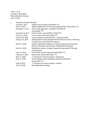
Original survey issued (see Exhibit “A”) Original application for permit including affidavit (see Exhibit “B”) Plan review approved—case #2017-043148 PR (see Exhibit “C”) Permit issued—permit #2017-152673 PR Form survey issued (see Exhibit “D”) Layout inspection passed by City—inspection #101 Development Services Department informed by District 3 Planning Commissioner of potential discrepancy Specific residential reviewers in charge of approval informed by District 3 Planning Commissioner of potential discrepancy Residential review in charge of approval responded to Planning Commissioner Post-permit revision approved (see Exhibit “E”) New survey issued (see Exhibit “F”) 1st hearing for variance request—postponed New drawings issued showing proposed modifications (see Exhibit “G”) 2nd hearing for variance request—denied Reconsideration hearing 1401 E. 3rd St. Case #C15-2020-0020 Reconsideration Hearing July 13, 2020 1. Summary of project timeline January 9, 2017 April 12, 2017 December 7, 2017 December 8, 2017 January 3, 2018 January 19, 2018 January 24, 2019 March 1, 2018 March 2, 2018 June 13, 2018 February 3, 2020 May 11, 2020 May 21, 2020 June 8, 2020 July 13, 2020 Rationales for reconsideration 2. A. In the previous meeting, it was questioned whether the project was legally approved. The previous agent mistakenly called the project a duplex. A duplex is not allowed on a lot this small or this narrow. The project was intended to be a single-family residence with an attached accessory apartment, as allowed by the zoning code in section 25-2-901. This section of code does not state a minimum lot size or dimension: An affidavit was submitted stating that the owner (over the age of 60) intended to occupy the accessory apartment (Exhibit “B”): Exhibit “B” was not presented in the previous two hearings. As well, the local Planning Commissioner questioned whether the project was legally approved due to the fact that he thought the building was too close to the east property line. The approved plans appeared to show that the building was too close to the east property line but it was only the eave, not the wall, that was approved to be within 5 feet of the east property line: B. As was said in the previous two meetings, the reason that the structure as-built is only 2.80 feet from the east property line, is due to a surveying error. The original survey (Exhibit “A”) indicated that the neighbor’s fence was the eastern property line: Exhibit “A” was not presented in the previous two hearings. When the surveyor returned to do the form survey, they felt they had reason to believe that the original survey was incorrect, and that the neighbor’s fence was actually on 1401’s property (as shown on Exhibit “D”): Exhibit “D” was not presented in the previous two hearings. Thus the contractor, owner, and City inspectors all had reason to believe that the position of the building in relation to the east property line was correct, and thus the layout survey was approved, and thus construction continued. It was only when the surveyor returned to the site to do the final survey, that they found that the structure is too close to the eastern property line (Exhibit “F”): Proposed modifications to alleviate the neighbor’s legitimate concerns about fire/life safety (not elaborated upon in 2nd hearing): • The entire building will be fire-sprinklered • Windows and doors will be removed from the portion of building that is less than 3 feet from east property line (as is required by the building code for walls less than 3 feet from property lines) • The portion of exterior wall that is less than 3 feet from east property line will be retrofitted to be 1-hour fire-rated from both inside and outside (as is required by the building code for walls less than 3 feet from property lines) • All of the above will be submitted to the Development Services Department for review and approval prior to any resumption of construction Conclusion A. This project was legally approved. B. This variance request is not the result of negligence nor is it the result of intentional encroachment in a side setback. The general vicinity is known for discrepancies in surveying and the surveyor made an honest mistake. Because that mistake was made in the form survey stage, everyone involved in approving the location of the building understandably thought that the building had been laid out correctly, and construction continued. The surveying mistake was not discovered until the final survey was done. Again, it was an honest mistake. C. Had the project been laid out according to the original survey, and had the project been built as approved, it would have had virtually the same visual and spatial relationship to the neighbor’s property as it does now. D. The proposed actions to alleviate the neighbor’s legitimate concerns about fire/life safety will be complex and expensive but we understand that they are required by the building code and we are more than willing and able to take them. 3. 4. P-4/11 AS-BUILT SITE CONDITIONS K C A B T E S R A E R ' 0 1 P P P P P P P P P P P P P P P P P P P CONCRETE PARKING AS-BUILT 14'-9" LENGTH OF REQUIRED RATED WALL NEW CONCRETE SIDEWALK SIDEWALK TO BE DELETED NEW CONCRETE SIDEWALK K C A B T E S T N O R F ' 5 2 15' SIDE SETBACK 5' SIDE SETBACK 3' FIRE-RATING SETBACK FIRE SPRINKLER SYSTEM TO BE INSTALLED. SYSTEM SHALL PROTECT ALL COVERED AND ENCLOSED SPACES. SYSTEM SHALL COMPLY WITH NFPA 13R STANDARDS. THIS SHEET IS FOR DEPICTION OF AS-BUILT SITE CONDITIONS ONLY. REFER TO SHEETS A101 AND A102 FOR EXTENTS OF RATED EXTERIOR WALLS. REFER TO SHEET G001 FOR PROJECT INFORMATION AND AREA CALCULATIONS. CONDITIONS DERIVED FROM CAD FILE OF SURVEY PROVIDED TO ARCHITECT. 1 Site Plan Scale 116" = 1'-0" @ 11x17 Scale 18" = 1'-0" @ 24x36 CRITICAL ROOT ZONES AT PROTECTED TREES. TREE PROTECTION LEGEND. SEAL OF ARCHITECT. SEAL OF MUNICIPAL APPROVAL. LIST OF PROTECTED TREES. SPECIES TRUNK Ø KEYED NOTES (NOT ALL NOTES MAY PERTAIN TO THIS SPECIFIC PROJECT). 01 02 03 04 05 06 07 14 15 12 13 New primary residence. New secondary residence. New attached garage. New attached carport. New detached garage, New detached carport. New covered porch w deck or habitable space above. New covered porch wo deck or habitable space above. New uncovered deck. New uncovered roof deck. New spiral stair to roof deck. 16 17 18 19 20 21 22 23 New wood deck, uncovered. New concrete patio, uncovered. New concrete driveway. New concrete driveway ribbon. New concrete sidewalk. New Type I driveway (approach) per City of Austin standards. New sidewalk in right-of-way per City of Austin standards. New overhead electric service, indicated thus: P P P P 08 09 10 11 New electrical meter(s) for primary and secondary residences, as applicable. Location of water meter (ref: civil engineering for final location). New water supply line to residences, indicated thus: New sewer line from residences (ref: civil engineering for final location of sewer tap), indicated thus: 24x TRUNK Ø 12x TRUNK Ø 6x TRUNK Ø OUTER CRITICAL ROOT ZONE MIDDLE (12) CRITICAL ROOT ZONE INNER (14) CRITICAL ROOT ZONE Mulch (3" layer of mulch inside tree protection fence, 8" layer outside). Tree protection fencing (ref: G007 and notes on this sheet). DISCLAIMERS. issued under the seal of is This document This document issued under the seal of is WILLIAM LAWRENCE HODGE, Texas architect WILLIAM LAWRENCE HODGE, Texas architect 19074. 19074. This document is not for permitting, This document is not for permitting, regulatory approval, pricing or construction regulatory approval, pricing or construction unless the seal and signature of the Architect are unless the seal and signature of the Architect are visible. visible. This document is not approved for This document is not approved for construction unless a seal of municipal approval construction unless a seal of municipal approval is visible. No set of construction documents can is visible. No set of construction documents can contain all information required to construct a contain all information required to construct a project. project. is is required. That which is shown in one sheet, required. That which is shown in one sheet, applies to all sheets in this set by reference. The applies to all sheets in this set by reference. The information in G001 through G009 (inclusive) information in G001 through G009 (inclusive) apply to every sheet in this set and to every apply to every sheet in this set and to every contractor andor subcontractor contractor andor subcontractor that may that may perform work on this project. Unless this set perform work on this project. Unless this set contains the cover sheet and all sheets listed contains the cover sheet and all sheets listed thereon, this set is incomplete and INVALID FOR thereon, this set is incomplete and INVALID FOR CONSTRUCTION. CONSTRUCTION. Interpretation by a contractor Interpretation by a contractor ISSUE DATE 21 May 2020 W I L L I A M H O D G E A I A A R C H I T E C T 4 8 0 1 S C O N G R E S S A V E N 3 A U S T I N , T X 7 8 7 4 5 5 1 2 . 7 8 6 . 9 2 9 8 H O D G E A R C H I T E C T . C O M NEW PROJECT AT 1401 E 3rd ST AUSTIN, TX 78702 ISSUE DATE SHEET TYPE 21 May 2020 As-Built Site Plan. A0 0 1 7'-3" 5'-61 2" 14'-7" 2'-21 4" 14'-101 2" 4'-01 2" 2'-41 2" 5'-61 2" 6'-8" 6'-81 2" 97'-71 4" 82'-31 4" 33 4" 2'-21 4" SH3660@80 E SH3660@80 E Bedroom 2 B101 CLNG HT 8' Bedroom 2 A101 CLNG HT 8' 3'-7" 3'-7" 1" 7'-2" 1'-0" 9 0 1 1 1 2 1 8 7 6 5 4 3 2 1 UP " 0 1 - ' 3 1 EN3680 Closet 2 A102 CLNG HT 8' 0 8 4 2 ) 2 ( D S Closet 1 A104 CLNG HT 8' 0 8 4 2 D S " 2 - ' 4 0 8 2 3 D S Bath 1 A103 CLNG HT 8' Stairs A107 UP CLNG HT 8' Corridor A106 CLNG HT 8' " 2 1 6 - ' 5 " 2 1 4 - ' 3 0 8 4 2 D S 0 8 2 3 D S SH3660@80 E SH3660@80 E PW6012@80 SH3660@80 E " 1 Bedroom 1 A105 CLNG HT 8' " 1 " 2 1 7 - ' 9 " 2 1 1 1 - ' 3 " 1 7'-10" 1" 1'-0" PD3280 1 2 3 4 5 6 7 8 9 10 11 12 13 14 14 13 12 11 10 9 8 7 6 5 4 3 2 1 PD3280 SD3280 SD3280 Closet BX01 5 Closet BX01 CLNG HT VARIES CLNG HT VARIES 3'-0" 3'-0" 9'-41 2" 7'-11" 8'-61 2" 8'-61 2" 2'-21 4" 2'-21 4" 8'-3" 8'-10" 6'-01 2" 4'-10" 14'-9" LENGTH OF REQUIRED RATED WALL 33 4" 80'-31 4" 1'-61 2" 1'-101 2" 3'-7" 3'-7" 1'-0" " 0 1 - ' 3 1 " 2 1 1 - ' 4 " 5 - ' 6 " 0 - ' 3 " 2 1 3 3'-7" 3'-7" 1" 3'-5" " 1 SH3660@80 E " 2 1 7 - ' 9 " 2 1 1 1 - ' 3 " 1 UP Bedroom 1 B105 CLNG HT 8' 1 2 3 4 5 6 7 8 1 1 0 1 9 " 2 - ' 4 " 2 1 6 - ' 5 " 2 1 4 - ' 3 31 2" 7" 31 2" 1" 7'-2" 1'-0" 0 8 4 2 D S Closet 1 B104 CLNG HT 8' 0 8 4 2 D S 0 8 2 3 D S Bath 1 B103 CLNG HT 8' 0 8 2 3 D S Corridor B106 CLNG HT 8' Stairs B107 CLNG HT 8' UP 2'-41 2" 4'-01 2" EN3680 Closet 2 B102 CLNG HT 8' 0 8 4 2 ) 2 ( D S SH3660@80 E 1'-10" KEYED NOTES (NOT ALL NOTES MAY PERTAIN TO THIS SPECIFIC PROJECT). 01 03 New 2-hr-rated demising wall between duplex units. Construction to comply with UL U373. REQUIRED: XX'-XX" PROVIDED: XX'-XX" 01a NEW OR RETROFIT 1-HR RATED EXTERIOR WALL COMPLIANT WITH UL U305. Railing or parapet at exterior porch or deck. Minimum height 36" above finish floor. Maximum openness 3.5". 02 04 05 06 07 08 Railing or partial-height wall at interior. Minimum height 36" above finish floor. Maximum openness 3.5". Open metal or wood railing at stair. Minimum height 36" above nosing of stair. Maximum openness 3.5". Ceiling break. Linen closet (cabinetry). Pantry (cabinetry). Access panel to AC. R1 R2 R3 R4 R5 New walkable-PVC roof deck. New metal coping. New metal scupper. New metal gutter. New metal downspout. NOTES ON FRAMING. 1. 2. 3. 4. 5. 6. Bathroom(s) on the first floor shall receive an entry door with minimum 30" clear opening. Bathroom(s) on the first floor shall receive 2x6 wood blocking parallel with floor (except directly behind lavatories). Blocking shall be installed such that the centerline of blocking is 34" above finish floor level. Switches and thermostats on all floors shall be located no greater than 45" (@ junction-box centerline) above finish floor level. Power receptacles and data ports on all floors shall be located no less than 18" (@ junction-box centerline) above finish floor level. At least one entrance to the first floor of the dwelling shall have a "no-step" entrance with a beveled threshold of 12" or less. A visitable route shall be provided from public way to the no-step entrance of each dwelling unit. Said visitable route shall be a minimum of 36" in clear width and shall have a maximum cross-slope of 1:50. Standing-seam metal roofing Composition-shingle roofing DISCLAIMERS. issued under the seal of is This document WILLIAM LAWRENCE HODGE, Texas architect 19074. This document is not for permitting, regulatory approval, pricing or construction unless the seal and signature of the Architect are visible. This document is not approved for construction unless a seal of municipal approval is visible. No set of construction documents can contain all information required to construct a project. is required. That which is shown in one sheet, applies to all sheets in this set by reference. The information in G001 through G009 (inclusive) apply to every sheet in this set and to every contractor andor subcontractor that may perform work on this project. Unless this set contains the cover sheet and all sheets listed thereon, this set is incomplete and INVALID FOR CONSTRUCTION. Interpretation by a contractor 2x4 wood framing 2x6 wood framing 2-hour rated firewall (per G005) COMPLIANT WITH UL ASSEMBLY U373 ISSUE DATE 21 May 2020 FRAMING AND ROOFING LEGEND. SEAL OF ARCHITECT. SEAL OF MUNICIPAL APPROVAL. 1 Floor Plan, Bldg 1, Level 01 Scale 18" = 1'-0" @ 11x17 Scale 14" = 1'-0" @ 24x36 W I L L I A M H O D G E A I A A R C H I T E C T 4 8 0 1 S C O N G R E S S A V E N 3 A U S T I N , T X 7 8 7 4 5 5 1 2 . 7 8 6 . 9 2 9 8 H O D G E A R C H I T E C T . C O M NEW PROJECT AT 1401 E 3rd ST AUSTIN, TX 78702 ISSUE DATE 21 May 2020 SHEET TYPE Floor Plans, Level 01. A 1 0 1 " 2 1 3 " 0 1 - ' 3 " 5 - ' 6 " 0 - ' 3 " 2 1 3 " 0 1 - ' 3 1 7'-2" 31 2" 0 8 6 3 N E DN UP 6 1 5 1 4 1 3 1 2 1 2 1 1 1 0 1 1 2 3 4 5 6 7 8 9 31 2" 31 2" 1" 7'-2" 3'-31 2" 3'-7" 4'-11" 11'-21 2" 6'-111 4" 8'-23 4" 3'-31 2" 8'-23 4" 6'-111 4" 11'-11 2" PW6060@80 SH3660@80 E PW3636@78 PW2424@72 PW2424@72 PW3636@78 SH3660@80 E PW6060@80 Great Room B203 CLNG HT 9' " 0 - ' 2 " 2 1 7 - ' 4 " 0 - ' 3 " 2 1 4 - ' 3 CHASE CHASE Half Bath B201 CLNG HT 9' Half Bath A201 CLNG HT 9' BUILT-IN SD3296 SD3296 BUILT-IN 3'-0" 4'-101 2" 4'-101 2" 3'-0" Kitchen B202 CLNG HT 9' 13'-31 2" Kitchen A202 CLNG HT 9' 13'-31 2" Great Room A203 CLNG HT 9' Laundry B204 CLNG HT 9' SD(2)1896 Stack W+D 2 3 4 5 6 7 8 9 10 11 12 13 14 15 15 14 13 12 11 10 9 8 7 6 5 4 3 2 Stairs B205 DN CLNG HT 9' Stairs A205 CLNG HT 9' DN SD(2)1896 Stack W+D Laundry A204 CLNG HT 9' 14'-9" LENGTH OF REQUIRED RATED WALL PW3660@96 PW3660@96 PW7212@96 PW7212@96 3'-31 2" 3'-31 2" 4'-11" 9'-71 2" 3'-41 2" 3'-81 2" 13'-11 2" 2'-51 2" 2'-51 2" 12'-10" 3'-81 2" 3'-8" 9'-71 2" 7'-11" 3'-31 2" 3'-31 2" 7'-2" 1" 3'-7" 3'-31 2" 31 2" 1'-0" 7'-11" " 1 " 5 - ' 2 " 1 - ' 9 0 8 6 3 N E " 2 - ' 2 " 1 S H 3 6 6 0 @ 8 0 E 9 8 7 6 5 4 3 2 0 1 1 1 2 1 3 1 4 1 5 1 6 1 7 1 DN " 2 1 3 " 0 1 - ' 3 1 " 2 1 3 " 0 - ' 3 " 5 - ' 6 " 0 1 - ' 3 31 1" 2" 31 2" 7'-2" 97'-71 4" 82'-31 4" 1" 3'-81 8" 1'-31 2" 1" 3'-81 8" 1'-31 2" 3'-31 2" 2'-41 8" 2'-41 8" 82'-31 4" KEYED NOTES (NOT ALL NOTES MAY PERTAIN TO THIS SPECIFIC PROJECT). 01 03 New 2-hr-rated demising wall between duplex units. Construction to comply with UL U373. REQUIRED: XX'-XX" PROVIDED: XX'-XX" 01a NEW OR RETROFIT 1-HR RATED EXTERIOR WALL COMPLIANT WITH UL U305. Railing or parapet at exterior porch or deck. Minimum height 36" above finish floor. Maximum openness 3.5". 02 04 05 06 07 08 Railing or partial-height wall at interior. Minimum height 36" above finish floor. Maximum openness 3.5". Open metal or wood railing at stair. Minimum height 36" above nosing of stair. Maximum openness 3.5". Ceiling break. Linen closet (cabinetry). Pantry (cabinetry). Access panel to AC. R1 R2 R3 R4 R5 New walkable-PVC roof deck. New metal coping. New metal scupper. New metal gutter. New metal downspout. NOTES ON FRAMING. 1. 2. 3. 4. 5. 6. Bathroom(s) on the first floor shall receive an entry door with minimum 30" clear opening. Bathroom(s) on the first floor shall receive 2x6 wood blocking parallel with floor (except directly behind lavatories). Blocking shall be installed such that the centerline of blocking is 34" above finish floor level. Switches and thermostats on all floors shall be located no greater than 45" (@ junction-box centerline) above finish floor level. Power receptacles and data ports on all floors shall be located no less than 18" (@ junction-box centerline) above finish floor level. At least one entrance to the first floor of the dwelling shall have a "no-step" entrance with a beveled threshold of 12" or less. A visitable route shall be provided from public way to the no-step entrance of each dwelling unit. Said visitable route shall be a minimum of 36" in clear width and shall have a maximum cross-slope of 1:50. Standing-seam metal roofing Composition-shingle roofing DISCLAIMERS. issued under the seal of is This document This document issued under the seal of is WILLIAM LAWRENCE HODGE, Texas architect WILLIAM LAWRENCE HODGE, Texas architect 19074. 19074. This document is not for permitting, This document is not for permitting, regulatory approval, pricing or construction regulatory approval, pricing or construction unless the seal and signature of the Architect are unless the seal and signature of the Architect are visible. visible. This document is not approved for This document is not approved for construction unless a seal of municipal approval construction unless a seal of municipal approval is visible. No set of construction documents can is visible. No set of construction documents can contain all information required to construct a contain all information required to construct a project. project. is is required. That which is shown in one sheet, required. That which is shown in one sheet, applies to all sheets in this set by reference. The applies to all sheets in this set by reference. The information in G001 through G009 (inclusive) information in G001 through G009 (inclusive) apply to every sheet in this set and to every apply to every sheet in this set and to every contractor andor subcontractor contractor andor subcontractor that may that may perform work on this project. Unless this set perform work on this project. Unless this set contains the cover sheet and all sheets listed contains the cover sheet and all sheets listed thereon, this set is incomplete and INVALID FOR thereon, this set is incomplete and INVALID FOR CONSTRUCTION. CONSTRUCTION. Interpretation by a contractor Interpretation by a contractor 2x4 wood framing 2x6 wood framing 2-hour rated firewall (per G005) COMPLIANT WITH UL ASSEMBLY U373 ISSUE DATE 21 May 2020 FRAMING AND ROOFING LEGEND. SEAL OF ARCHITECT. SEAL OF MUNICIPAL APPROVAL. 1 Floor Plan, Bldg 1, Level 02 Scale 18" = 1'-0" @ 11x17 W I L L I A M H O D G E A I A A R C H I T E C T 4 8 0 1 S C O N G R E S S A V E N 3 A U S T I N , T X 7 8 7 4 5 5 1 2 . 7 8 6 . 9 2 9 8 H O D G E A R C H I T E C T . C O M NEW PROJECT AT 1401 E 3rd ST AUSTIN, TX 78702 ISSUE DATE 21 May 2020 SHEET TYPE Floor Plans, Level 02. A 1 02 32' maximum height per CoA RDCS SECTION 2 RDCS SECTION 2 ° 5 4 45° 12 12 ° 5 4 k c a b t e S e d S i ' 5 1 " 0 - ' 5 1 i e n L y t r e p o r P r a e R " 0 - ' 5 1 i e n L y t r e p o r P r a e R k c a b t e S e d S i ' 5 1 " 0 - ' 5 1 i e n L y t r e p o r P r a e R k c a b t e S e d S i ' 5 99'-10" HP02 99'-10" HP02 ROOF TRailing (CoA Highpoint) ROOF TDeck L2 TPlate 12 12 45° " 4 1 5 - ' 1 " 4 1 5 - ' 1 " 0 - ' 3 " 8 1 1 - ' 9 " 8 1 1 - ' 8 " 0 - ' 2 L2 TDeck L1 TPlate " 0 - ' 5 1 i e n L y t r e p o r P r a e R k c a b t e S e d S i ' 5 " 4 3 0 - ' 5 2 " 4 3 0 - ' 3 2 " 0 - ' 2 3 L1 FFE (101'-0") FFE (99'-9")@carports AAG (99'-6") KEYED NOTES. 01 New metal coping. Exposure 6". New metal flashing. Exposure 6" minimum. New metal railing at exterior porch or deck. Minimum height 36" above finish floor. Maximum opening 3.5". New parapet at exterior porch or deck. Minimum 36" above finish floor. New through-wall scupper. New metal downspout. Steel column (ref: structural). 02 03 04 05 06 07 CODE REFERENCES (City of Austin RDCS area only). LDC TITLE 25, CHAPTER 25-2, SUBCHAPTER F, ARTICLE 2.6, E, 4, b, (i): A structure may not extend beyond a setback plane...except for gables or a shed roof, with a total horizontal length of not more than 18 feet on each side of the building, measured along the intersection with the setback plane. ARCHITECT'S NOTE: NO PROVISIONS FOR "HABITABILITY OF SPACE" ARE MADE IN THE LANGUAGE CITED ABOVE. IE: ANY ENCLOSED SPACE UNDER THE SHED ROOF MAY PROTRUDE, INCLUDING SPACE USED FOR VERTICAL CIRCULATION. LDC TITLE 25, CHAPTER 25-2, SUBCHAPTER F, ARTICLE 3.4.1 Height shall be measured vertically from the average of the highest and lowest grades adjacent to the building to...for a pitched or hip roof, the gabled roof or dormer with the highest average height. 1 Elevation, Bldg 1, Front Scale 18" = 1'-0" @ 11x17 Scale 14" = 1'-0" @ 24x36 MATERIALS LEGEND. SEAL OF ARCHITECT. SEAL OF MUNICIPAL APPROVAL. Standing-seam metal roofing Composition-shingle roofing Cement-board or RealTrim fascia Cement-board trim or RealTrim 6" horizontal cement board 6" horizontal stained wood 24" vertical cement board Stone veneer (ashlar bond) ISSUE DATE 21 May 2020 DISCLAIMERS. issued under the seal of is This document WILLIAM LAWRENCE HODGE, Texas architect 19074. This document is not for permitting, regulatory approval, pricing or construction unless the seal and signature of the Architect are visible. This document is not approved for construction unless a seal of municipal approval is visible. No set of construction documents can contain all information required to construct a project. is required. That which is shown in one sheet, applies to all sheets in this set by reference. The information in G001 through G009 (inclusive) apply to every sheet in this set and to every contractor andor subcontractor that may perform work on this project. Unless this set contains the cover sheet and all sheets listed thereon, this set is incomplete and INVALID FOR CONSTRUCTION. Interpretation by a contractor W I L L I A M H O D G E A I A A R C H I T E C T 4 8 0 1 S C O N G R E S S A V E N 3 A U S T I N , T X 7 8 7 4 5 5 1 2 . 7 8 6 . 9 2 9 8 H O D G E A R C H I T E C T . C O M NEW PROJECT AT 1401 E 3rd ST AUSTIN, TX 78702 ISSUE DATE SHEET TYPE 21 May 2020 Elevations. A 2 0 1 TO BUILDING LINE 40'-0" RDCS SECTION 1 40'-0" RDCS SECTION 2 26'-13 4" RDCS SECTION 3 10'-0" Rear Setback 12:12 32' maximum height per CoA ROOF TRailing (CoA Highpoint) ROOF TDeck L2 TPlate " 4 1 5 - ' 1 " 4 1 5 - ' 1 " 0 - ' 3 " 8 1 1 - ' 9 " 8 1 1 - ' 8 " 0 - ' 2 L2 TDeck L1 TPlate " 4 3 0 - ' 5 2 " 4 3 0 - ' 3 2 " 0 - ' 2 3 L1 FFE (101'-0") FFE (99'-9")@carports AAG (99'-6") ° 5 4 i e n L y t r e p o r P r a e R " 0 - ' 5 1 100'-0" HP01 99'-10" HP02 99'-8" HP03 99'-0" HP04 KEYED NOTES. 01 New metal coping. Exposure 6". New metal flashing. Exposure 6" minimum. New metal railing at exterior porch or deck. Minimum height 36" above finish floor. Maximum opening 3.5". New parapet at exterior porch or deck. Minimum 36" above finish floor. New through-wall scupper. New metal downspout. Steel column (ref: structural). 02 03 04 05 06 07 CODE REFERENCES (City of Austin RDCS area only). LDC TITLE 25, CHAPTER 25-2, SUBCHAPTER F, ARTICLE 2.6, E, 4, b, (i): A structure may not extend beyond a setback plane...except for gables or a shed roof, with a total horizontal length of not more than 18 feet on each side of the building, measured along the intersection with the setback plane. ARCHITECT'S NOTE: NO PROVISIONS FOR "HABITABILITY OF SPACE" ARE MADE IN THE LANGUAGE CITED ABOVE. IE: ANY ENCLOSED SPACE UNDER THE SHED ROOF MAY PROTRUDE, INCLUDING SPACE USED FOR VERTICAL CIRCULATION. LDC TITLE 25, CHAPTER 25-2, SUBCHAPTER F, ARTICLE 3.4.1 Height shall be measured vertically from the average of the highest and lowest grades adjacent to the building to...for a pitched or hip roof, the gabled roof or dormer with the highest average height. 1 Elevation, Bldg 1, Right Scale 18" = 1'-0" @ 11x17 Scale 14" = 1'-0" @ 24x36 MATERIALS LEGEND. SEAL OF ARCHITECT. SEAL OF MUNICIPAL APPROVAL. Standing-seam metal roofing Composition-shingle roofing Cement-board or RealTrim fascia Cement-board trim or RealTrim 6" horizontal cement board 6" horizontal stained wood 24" vertical cement board Stone veneer (ashlar bond) ISSUE DATE 21 May 2020 DISCLAIMERS. issued under the seal of is This document WILLIAM LAWRENCE HODGE, Texas architect 19074. This document is not for permitting, regulatory approval, pricing or construction unless the seal and signature of the Architect are visible. This document is not approved for construction unless a seal of municipal approval is visible. No set of construction documents can contain all information required to construct a project. is required. That which is shown in one sheet, applies to all sheets in this set by reference. The information in G001 through G009 (inclusive) apply to every sheet in this set and to every contractor andor subcontractor that may perform work on this project. Unless this set contains the cover sheet and all sheets listed thereon, this set is incomplete and INVALID FOR CONSTRUCTION. Interpretation by a contractor W I L L I A M H O D G E A I A A R C H I T E C T 4 8 0 1 S C O N G R E S S A V E N 3 A U S T I N , T X 7 8 7 4 5 5 1 2 . 7 8 6 . 9 2 9 8 H O D G E A R C H I T E C T . C O M NEW PROJECT AT 1401 E 3rd ST AUSTIN, TX 78702 ISSUE DATE SHEET TYPE 21 May 2020 Elevations. A 2 02 26'-13 4" RDCS SECTION 3 40'-0" RDCS SECTION 2 40'-0" RDCS SECTION 1 TO BUILDING LINE 32' maximum height per CoA ROOF TRailing (CoA Highpoint) ROOF TDeck L2 TPlate 45° " 4 1 5 - ' 1 " 4 1 5 - ' 1 " 0 - ' 3 " 8 1 1 - ' 9 " 8 1 1 - ' 8 " 0 - ' 2 L2 TDeck L1 TPlate " 0 - ' 5 1 i e n L y t r e p o r P r a e R L1 FFE (101'-0") FFE (99'-9")@carports AAG (99'-6") " 4 3 0 - ' 5 2 " 4 3 0 - ' 3 2 " 0 - ' 2 3 " 8 - ' 6 12:12 " 8 - ' 6 99'-0" HP04 99'-8" HP03 99'-10" HP02 100'-0" HP01 KEYED NOTES. 01 New metal coping. Exposure 6". New metal flashing. Exposure 6" minimum. New metal railing at exterior porch or deck. Minimum height 36" above finish floor. Maximum opening 3.5". New parapet at exterior porch or deck. Minimum 36" above finish floor. New through-wall scupper. New metal downspout. Steel column (ref: structural). 02 03 04 05 06 07 CODE REFERENCES (City of Austin RDCS area only). LDC TITLE 25, CHAPTER 25-2, SUBCHAPTER F, ARTICLE 2.6, E, 4, b, (i): A structure may not extend beyond a setback plane...except for gables or a shed roof, with a total horizontal length of not more than 18 feet on each side of the building, measured along the intersection with the setback plane. ARCHITECT'S NOTE: NO PROVISIONS FOR "HABITABILITY OF SPACE" ARE MADE IN THE LANGUAGE CITED ABOVE. IE: ANY ENCLOSED SPACE UNDER THE SHED ROOF MAY PROTRUDE, INCLUDING SPACE USED FOR VERTICAL CIRCULATION. LDC TITLE 25, CHAPTER 25-2, SUBCHAPTER F, ARTICLE 3.4.1 Height shall be measured vertically from the average of the highest and lowest grades adjacent to the building to...for a pitched or hip roof, the gabled roof or dormer with the highest average height. 1 Elevation, Bldg 1, Left Scale 18" = 1'-0" @ 11x17 Scale 14" = 1'-0" @ 24x36 MATERIALS LEGEND. SEAL OF ARCHITECT. SEAL OF MUNICIPAL APPROVAL. Standing-seam metal roofing Composition-shingle roofing Cement-board or RealTrim fascia Cement-board trim or RealTrim 6" horizontal cement board 6" horizontal stained wood 24" vertical cement board Stone veneer (ashlar bond) ISSUE DATE 21 May 2020 DISCLAIMERS. issued under the seal of is This document WILLIAM LAWRENCE HODGE, Texas architect 19074. This document is not for permitting, regulatory approval, pricing or construction unless the seal and signature of the Architect are visible. This document is not approved for construction unless a seal of municipal approval is visible. No set of construction documents can contain all information required to construct a project. is required. That which is shown in one sheet, applies to all sheets in this set by reference. The information in G001 through G009 (inclusive) apply to every sheet in this set and to every contractor andor subcontractor that may perform work on this project. Unless this set contains the cover sheet and all sheets listed thereon, this set is incomplete and INVALID FOR CONSTRUCTION. Interpretation by a contractor W I L L I A M H O D G E A I A A R C H I T E C T 4 8 0 1 S C O N G R E S S A V E N 3 A U S T I N , T X 7 8 7 4 5 5 1 2 . 7 8 6 . 9 2 9 8 H O D G E A R C H I T E C T . C O M NEW PROJECT AT 1401 E 3rd ST AUSTIN, TX 78702 ISSUE DATE SHEET TYPE 21 May 2020 Elevations, Bldg 1. A 2 04